


- Protocols

- Articles and Issues
- For Authors
- About
- Become a Reviewer


Microtube-Assisted Paraffin Embedding and Sectioning of Fragile 3D Tumor Spheroids for High-Quality Histology



Published: Vol 16, Iss 21, Nov 5, 2026 DOI: 10.21769/BioProtoc.5850 Views: 25
Reviewed by: Hima Bindu DurumutlaAnonymous reviewer(s)
 PDF
PDF  Ask a question

Protocol Collections
Comprehensive collections of detailed, peer-reviewed protocols focusing on specific topics




Abstract
Three-dimensional (3D) spheroid models have become essential in cancer biology, drug screening, and tissue engineering. However, their small size, fragile structure, and tendency to disintegrate during routine histoprocessing present persistent technical challenges. Conventional paraffin embedding often results in tissue fragmentation, loss of spatial orientation, and poor section quality, whereas cryosectioning often compromises cellular morphology. Here, we present a robust, cost-effective protocol for preserving and sectioning fragile 3D spheroids, resulting in high-quality histological sections with intact architecture and excellent cellular detail. The method involves optimized handling and embedding procedures that stabilize spheroids during standard formalin fixation, paraffin infiltration, and microtomy, eliminating mechanical distortion and preserving spherical integrity for consistent sectioning. We demonstrate the successful application of this protocol across different tumor spheroids derived from distinct tissue types, including MDA-MB-231 (breast carcinoma), Caco-2 (colorectal adenocarcinoma), and A549 (lung carcinoma) cell lines, with subsequent compatibility with hematoxylin and eosin (H&E) staining protocols. This protocol is compatible with immunohistochemistry (IHC) and immunofluorescence (IF). In our qualitative comparison with conventional methods, we found that our approach effectively limits sample loss, promotes consistent inter-section reproducibility, and preserves fine structural features, such as necrotic cores, proliferative zones, and extracellular matrix components. This protocol provides a reliable, accessible solution for routine histological analysis of fragile 3D spheroids, facilitating more accurate morphological assessment in translational research settings.
Key features
• Cost-effective agarose-coated plates for reproducible spheroid formation.
• Complete in-tube processing to minimize sample loss and damage.
• Floating tube system for reliable paraffin infiltration without specialized equipment.
• Produces high-quality sections compatible with H&E.
Keywords: 3D spheroids Paraffin embedding
FFPE
Microtome sectioning
Histological analysis
Paraffin embedding
FFPE
Microtome sectioning
Histological analysis
Graphical overview
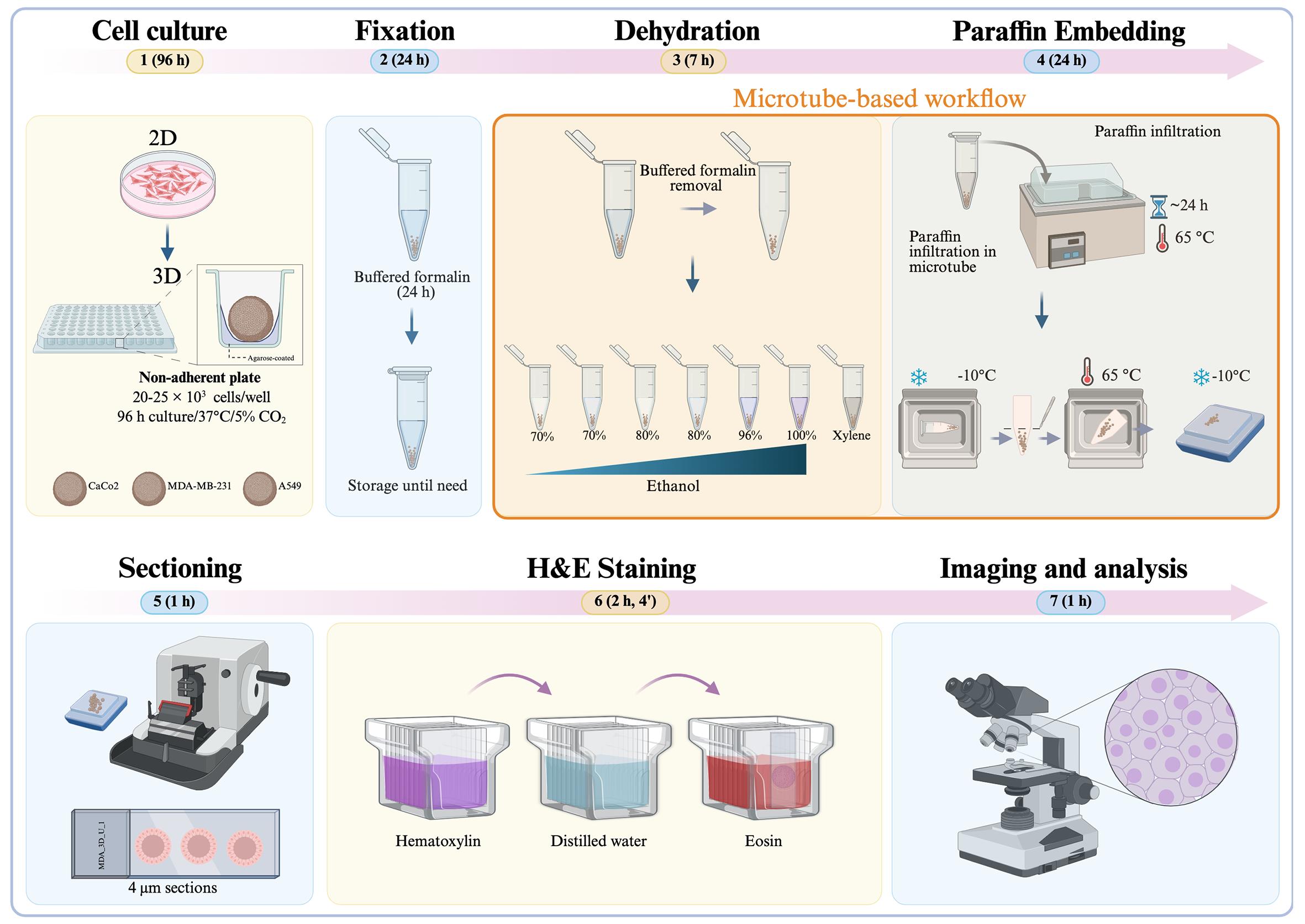
Background
Three-dimensional (3D) tumor models have advanced to become in vitro platforms that more accurately mimic the biological complexity of cancer than traditional two-dimensional (2D) monolayer cultures [1]. Cancer is a multifactorial and diverse disease characterized by uncontrolled cell growth, genomic instability, metabolic reprogramming, immune evasion, and the ability to invade and metastasize [2]. Notably, these processes are heavily influenced by the tumor microenvironment (TME), which includes oxygen and nutrient gradients, extracellular matrix (ECM) composition, biomechanical forces, and cell-to-cell communication [3]. While 2D systems are convenient for experiments, they do not replicate the spatial organization and microenvironmental conditions that control tumor behavior. Cells in 2D cultures assume an unnatural flat shape, with unlimited apical diffusion and limited basal attachment, lacking proper cell-cell contacts and a three-dimensional structure that regulates cell signaling, gene expression, and drug response. As a result, 2D models have limited relevance and predictive ability in preclinical drug testing [1].
3D tumor models include various platforms such as multicellular spheroids, organoids, scaffold-based cultures, and bioprinted constructs. Among these, tumor spheroids are particularly popular and cost-effective [3]. In non-adherent culture conditions, tumor cells spontaneously form compact multicellular aggregates that develop inherent structural organization and physiologically relevant gradients of oxygen, nutrients, metabolites, and signaling molecules. These gradients create spatially distinct cellular zones, including an outer proliferative layer, intermediate quiescent regions, and a central hypoxic or necrotic core, closely mimicking avascular tumor regions in vivo [4]. The radial structure of spheroids, with a high-oxygen, nutrient-rich outer layer and a progressively hypoxic, nutrient-deprived center, reflects the key mass-transfer limitations seen in solid tumors. This stratification enables researchers to investigate pathophysiological processes such as oxygen- and nutrient-driven metabolic adaptation, hypoxia-inducible factor (HIF)-mediated signaling, and the transition from quiescence to necrosis in a precisely controlled environment [5].
Establishing spatial heterogeneity within spheroids has significant implications for cancer research. Cells in different regions of the spheroid exhibit distinct transcriptional programs, metabolic states, proliferative capacities, and responses to stress. Hypoxic cores activate pathways such as HIF-mediated signaling, which promote metabolic adaptation and survival under nutrient deprivation [5]. Additionally, increased cell-cell adhesion, changes in polarity, and endogenous ECM deposition create diffusion barriers that affect drug penetration and therapeutic response. Consequently, spheroids model clinically relevant phenomena such as chemoresistance, microenvironment-driven plasticity, and treatment-induced selective pressures more effectively than 2D cultures [6]. Recent studies have demonstrated that including stromal or immune cell, such as co-culturing cancer cells with macrophages, can be integrated into spheroid models to imitate the complex cellular interactions of the TME, allowing tracking of region-specific changes in hypoxia, apoptosis, and metabolic profiles across the radial axis [3,7].
The use of 3D models greatly influences the study of cancer progression and drug development. Drug screening in spheroids often shows lower drug sensitivity compared to 2D cultures, emphasizing the importance of the microenvironment in treatment response [1]. Additionally, 3D systems allow investigation of tumor-matrix interactions, invasive behavior, and ECM remodeling when combined with biomimetic matrices such as collagen, matrigel, or synthetic hydrogels. These matrix-embedded systems mimic biomechanical constraints and stromal interactions found in vivo, offering a more realistic framework for studying tumor adaptation and growth [7]. For example, embedding spheroids in collagen I hydrogels enables direct observation of cells escaping from the tumor mass and invading surrounding tissue, a process key to metastasis and drug resistance [7]. The ability to observe such events in both space and time makes 3D spheroids especially useful for mechanistic research and developing anti-invasive treatments [3].
Despite these advantages, 3D spheroid models pose technical challenges, particularly during downstream histological processing. Because they are small, have compact cellular structures, and lack intrinsic support, spheroids are very prone to deformation, fragmentation, or loss during fixation, dehydration, paraffin embedding, and microtome sectioning [4,8]. Matrix-embedded spheroids face extra difficulties, as mechanical mismatch or uneven shrinkage between the spheroid and the surrounding hydrogel can weaken their structure [7]. Their small size also makes spheroids difficult to locate and position within a paraffin block, and incomplete dehydration or poor paraffin infiltration can lead to voids, tearing, or complete loss during sectioning [9,10]. As a result, many researchers choose low-resolution whole-mount imaging or cryosectioning, both of which trade off either spatial detail or molecular preservation [8].
Histological sectioning is crucial for thoroughly characterizing spheroids. While live imaging and viability assays offer overall functional insights, they cannot reveal the internal structure or localized treatment effects [11]. Histological analysis allows direct visualization of proliferative zones, hypoxic regions, necrotic cores, and area-specific therapeutic damage at a microscopic level [12]. Additionally, formalin-fixed, paraffin-embedded (FFPE) sections are preferable to whole-mount preparations for many applications, such as immunohistochemistry, because they prevent the depth-related antibody penetration issues seen in thick samples and enable long-term storage in biobanks [8]. Consequently, developing optimized and consistent histological workflows is essential for unlocking the full analytical potential of 3D tumor spheroid systems [9,10].
In this context, developing tailored, step-by-step histological protocols specifically adapted for 3D spheroid models is necessary to ensure structural preservation, reproducibility, and reliable spatial analysis [4,13]. These methodological improvements support the wider adoption of 3D tumor models in cancer biology research, drug discovery, and preclinical evaluation [1,3].
Materials and reagents
Biological materials
1. MDA-MB-231 cell line (ATCC, catalog number: CRM-HTB-26)
2. A549 cell line (ATCC, catalog number: CRM-CCL-185)
3. Caco-2 cell line (ATCC, catalog number: HTB-37)
Reagents
1. 10% neutral buffered formalin (J.T. Baker, catalog number: 2106-03)
2. Phosphate-buffered saline (1× PBS) (commercial or lab-made)
3. Ethanol (Meyer, catalog number: 0390)
4. Xylene (J.T. Baker, catalog number: 9490-03)
5. Paraffin wax, histology grade (melting point 56–60 °C) (Sigma-Aldrich, catalog number: 1.07164.2504)
6. Hematoxylin solution (Hycel, catalog number: 738)
7. Eosin Y solution (Sigma-Aldrich, catalog number: 45380)
8. Lithium carbonate (Fagan Lab, catalog number: 2518)
9. Synthetic resin for mounting (Sigma-Aldrich, catalog number: 1.07960.0500)
10. Methanol (J.T. Baker, catalog number: 9070-03)
11. Dulbecco’s modified Eagle medium (DMEM) (Sigma Merck, catalog number: D5648) or RPMI media
12. Sodium bicarbonate (NaHCO3) (J.T. Baker, catalog number: 3506-01)
13. L-glutamine (Gibco, catalog number: 20530-081)
14. Amphotericin B (Sigma-Aldrich, catalog number: A2942)
15. Fetal bovine serum (FBS) (BioWest, catalog number: BIO-S1400)
16. Bovine calf serum (BCS) (BioWest, catalog number: S0400-500)
17. Penicillin-streptomycin (Gibco, catalog number: 15140-122)
18. Trypsin (Sigma-Aldrich, catalog number: T4799-5G)
19. Ethylenediaminetetraacetic acid (EDTA) (J.T. Baker, catalog number: 8993-01)
20. Dimethyl sulfoxide (DMSO) (Sigma-Aldrich, catalog number: D2650)
21. Actinomycin D (Sigma-Aldrich, catalog number: A9415)
22. Potassium chloride (J.T. Baker, catalog number: 3040-01)
23. Sodium chloride (J.T. Baker, catalog number: 3624-01)
24. Disodium phosphate (Na2HPO4) (J.T. Baker, catalog number: 3828-01)
25. Monobasic potassium phosphate (KH2PO4) (J.T. Baker, catalog number: 3246-01)
25. Agarose (Invitrogen, catalog number: 16500-100)
27. MilliQ water, sterile (J.T. Baker, catalog number: 4220-20)
28. Hydrochloric acid (HCl) (J.T. Baker, catalog number: 9535-05)
29. Sodium hydroxide (NaOH) (Macron, Fine Chemicals, catalog number: 7708-10)
30. Sodium dihydrogen phosphate (NaH2PO4) (J.T. Baker, catalog number: 10049-21-5)
Laboratory supplies
1. 96-well cell culture plate (NEST, catalog number: 701002)
2. Cell culture dish (60 mm × 15 mm) (NEST, catalog number: 705007)
3. Conical-bottom centrifuge tube, 50 mL (Uniparts, catalog number: 32117F)
4. Conical-bottom centrifuge tube, 15 mL (Uniparts, catalog number: 34117F)
5. Microcentrifuge tubes 1.5 mL (Axygen, catalog number: MCT-150-C)
6. Pipette tip 100–1,000 μL (Uniparts, catalog number: 51131)
7. Pipette tip 1–200 μL (Uniparts, catalog number: 51121Y)
8. Pipette tip 0.5–10 μL (Axygen, catalog number: T-300)
9. Embedding molds (CR Globe, catalog number: P2030)
10. Microscope slide (BRAND, catalog number: BR474701)
11. Cover glasses for microscope slides (BRAND, catalog number: 470045)
12. Surgical design disposable scalpels (Fisher Scientific, catalog number: 22-079-707)
Solutions
1. Culture medium for MDA-MB-231, Caco-2, and A549 cell lines (supplemented DMEM) (see Recipes)
2. 1.5% agarose solution (see Recipes)
3. 1× PBS (see Recipes)
4. 0.04% trypsin-EDTA (see Recipes)
5. 500 μM Actinomycin D (see Recipes)
6. Ethanol solutions (see Recipes)
7. Eosin solution (see Recipes)
8. 10% neutral buffered formalin (see Recipes)
9. Lithium carbonate bluing solution (see Recipes)
10. 1 M HCl (see Recipes)
11. 1 M NaOH (see Recipes)
Recipes
1. Supplemented DMEM
| Reagent | Final concentration | Quantity |
| DMEM powder | - | 15.6 g |
| NaHCO3 | 3 g/L | 3 g |
| FBS | 5% (v/v) | 50 mL |
| BCS | 5% (v/v) | 50 mL |
| Penicillin-streptomycin | 1% (v/v) | 10 mL |
| Amphotericin B | 0.05% (v/v) | 500 μL |
| L-glutamine (200 mM) | 0.05% (v/v) | 500 μL |
| Sterile distilled water | - | To 1 L final volume |
1. Base medium preparation:
a. Combine the DMEM powder with sterile distilled water and stir continuously until fully dissolved.
b. Add 3 g of NaHCO3 to the solution.
c. Adjust the pH to 7.4 by carefully adding 1 M NaOH or 1 M HCl dropwise as required.
2. Supplementation (perform inside a laminar flow hood): Add the following components to the base medium:
a. 5% FBS → 50 mL
b. 5% BCS → 50 mL
c. 1% penicillin-streptomycin → 10 mL
d. 0.05% amphotericin B → 500 μL
e. 0.05% L-glutamine (200 mM stock) → 500 μL
3. Final sterilization and storage:
a. Filter-sterilize the complete medium using a vacuum filtration system equipped with a 0.22 μm MCE membrane.
b. Store the sterile medium at 4 °C and use within 4 weeks.
Notes:
1. This formulation is routinely used for culturing MDA-MB-231 cells; RPMI medium also works.
2. The formulation for Caco-2 and A549 is the same, but without 0.05% L-glutamine.
2. 1.5% agarose solution
| Reagent | Final concentration | Quantity |
| Agarose | 1.5% (w/v) | 1.5 g |
| Triple-distilled water | - | To 100 mL |
| Final volume | - | 100 mL |
a. In a glass flask, combine 1.5 g of agarose with 100 mL of triple-distilled water.
b. Autoclave the mixture for 15 min to achieve sterility.
Note: This solution is intended to create non-adherent surfaces in standard 96-well plates. After autoclaving, it should be used immediately or kept at approximately 60–70 °C until ready to dispense.
3. 1× PBS (pH 7.4)
| Reagent | Final concentration | Quantity |
| NaCl | 137 mM | 8.0 g |
| KCl | 2.7 mM | 0.2 g |
| Na2HPO4 | 10 mM | 1.44 g |
| KH2PO4 | 1.8 mM | 0.24 g |
| ddH2O | - | 1 L |
a. Dissolve NaCl (8.0 g), KCl (0.2 g), Na2HPO4 (1.44 g), and KH2PO4 (0.24 g) in approximately 800 mL of distilled water using a magnetic stirrer. Continue stirring until the solution is completely clear and free of any undissolved particulates.
b. Calibrate the pH meter using standard buffer solutions. Then, while continuously stirring, titrate the solution to pH 7.4 by adding 1 M HCl or 1 M NaOH drop by drop. Allow the pH reading to stabilize for 15–20 s after each addition before recording the value.
c. Transfer the solution to a 1 L volumetric flask and bring the total volume to exactly 1 L with distilled water. Mix thoroughly by inverting the capped flask at least five times to ensure homogeneity.
d. Pour the solution into an autoclave-safe bottle, loosen the cap slightly to permit pressure equilibration, and autoclave at 121 °C (15 psi) for 20–30 min.
e. After autoclaving, let the solution cool to room temperature before use. If not used immediately, store it under appropriate conditions (e.g., 4 °C for short-term storage) and label the bottle with the solution name, pH, and preparation date.
4. 0.04% trypsin-EDTA
| Reagent | Final concentration | Quantity |
| Trypsin | 0.04% (w/v) | 390 mg |
| EDTA | 0.037% (w/v) | 370 mg |
| NaCl | - | 85 mg |
| PBS 1× | - | To 1 L |
| Final volume | - | 1 L |
a. Use 1 L of 1× PBS (homemade or commercial).
b. In a separate sterile container, dissolve 390 mg of trypsin and 85 mg of NaCl in 10 mL of the prepared PBS. Mix gently until completely dissolved.
c. Add 370 mg of EDTA to the remaining PBS (approximately 990 mL) and stir until fully dissolved.
d. Add the trypsin-NaCl solution to the EDTA-containing PBS and stir thoroughly to ensure even mixing.
e. Under aseptic conditions, filter-sterilize the combined solution using a 0.22 μm vacuum filtration unit.
f. Divide the sterile solution into appropriate aliquots, clearly label each with the concentration and date, and store at -20 °C until use.
5. 500 μM actinomycin D
| Reagent | Final concentration | Quantity |
| Actinomycin D | 3,980 μM | 5 mg |
| DMSO | 100% | 1 mL |
Actinomycin D is a powerful cytotoxic and teratogenic agent. Always wear appropriate personal protective equipment (PPE), such as gloves and safety goggles, and handle all materials in a designated chemical fume hood or biological safety cabinet.
Prepare the actinomycin D stock at 3,980 μM in 100% DMSO.
a. Under sterile conditions in a cell culture hood, dilute the stock in sterile 1× PBS to a final concentration of 500 μM.
b. To prepare 1 mL of 500 μM actinomycin D, combine 874.38 μL of sterile 1× PBS with 125.62 μL of the 3,980 μM stock in a sterile 1.5 mL microtube.
c. Mix thoroughly by gentle pipetting or vortexing until fully dissolved.
d. Protect the solution from the light by transferring it to amber microcentrifuge tubes or wrapping standard tubes in aluminum foil.
e. Clearly label each tube with the compound name, concentration, and preparation date.
f. Store aliquots at -20 °C, protected from light. Avoid repeated freeze-thaw cycles.
6. Ethanol solutions
| Reagent | Final concentration | Quantity or volume |
| Absolute ethanol | 70/80/96% (v/v) | 70/80/96 mL |
| Distilled water | - | 30/20/4 mL |
| Final volume | - | 100 mL |
To prepare 100 mL of each concentration, mix absolute ethanol with distilled water as follows:
70% ethanol: 70 mL of absolute ethanol + 30 mL of distilled water.
80% ethanol: 80 mL of absolute ethanol + 20 mL of distilled water.
96% ethanol: 96 mL of absolute ethanol + 4 mL of distilled water.
Combine the two components in a suitable container and mix thoroughly.
7. Eosin solution
| Reagent | Final concentration | Quantity or volume |
| Eosin Y powder | 1% (w/v) | 1 g |
| Distilled water | - | 80 mL |
| Absolute ethanol | 20% (v/v) | 20 mL |
| Glacial acetic acid | 0.25% (v/v) | 0.25 mL |
| Final volume | - | 100 mL |
a. In a glass container, dissolve 1 g of eosin Y powder in 80 mL of distilled water.
b. Add 20 mL of absolute ethanol and mix until the powder is fully dissolved.
c. Add 0.25 mL of glacial acetic acid to enhance cytoplasmic staining.
d. Carefully stir the solution until it is uniform.
e. If necessary, filter the solution, then transfer it to an amber bottle and store it at room temperature.
8. 10% neutral buffered formalin
| Reagent | Final concentration | Quantity or volume |
| Commercial formaldehyde (37%–40%) | 10% (v/v) | 100 mL |
| Sodium dihydrogen phosphate (NaH2PO4) | - | 4 g |
| Disodium hydrogen phosphate (Na2HPO4) | - | 6.5 g |
| Distilled water | - | 900 mL |
| Final volume | - | 1 L |
a. Dissolve 4 g of sodium dihydrogen phosphate (NaH2PO4) and 6.5 g of disodium hydrogen phosphate (Na2HPO4) in 900 mL of distilled water.
b. Add 100 mL of commercial formaldehyde solution (37%–40%).
c. Mix thoroughly and confirm that the final pH is approximately 7.0.
d. Label the container and store at room temperature.
9. Lithium carbonate bluing solution
| Reagent | Final concentration | Quantity or volume |
| Lithium carbonate (Li2CO3) | 0.1% (w/v) | 0.1 g |
| Distilled water | - | 100 mL |
| Final volume | - | 100 mL |
a. Weigh 0.1 g of lithium carbonate and dissolve it in 100 mL of distilled water.
b. Mix thoroughly until fully dissolved.
c. Label the container.
d. Store at room temperature. For best results, prepare fresh when possible.
10. 1 M HCl
| Reagent | Final concentration | Quantity |
| 37% HCl | 1 M | 9.05 mL |
| MilliQ water | - | Up to 100 mL |
a. Put on gloves and safety goggles. Work inside a fume hood.
b. Measure 9.05 mL of 37% HCl using a graduated cylinder or pipette.
c. Add approximately 50–70 mL of Milli-Q water to a 100 mL volumetric flask.
d. Slowly pour the measured HCl into the water while gently swirling the flask.
e. Allow the solution to cool to room temperature (the flask will become warm).
f. Top up with Milli-Q water to the 100 mL mark (meniscus at eye level).
g. Mix thoroughly by inverting the capped flask at least five times.
h. Transfer to a labeled glass bottle and store at room temperature.
Caution: Always add acid to water, never water to acid.
11. 1 M NaOH
| Reagent | Final concentration | Quantity |
| NaOH | 1 M | 4 g |
| MilliQ water | - | Up to 100 mL |
a. Put on gloves and safety goggles. Work in a well-ventilated area or inside a fume hood.
b. Weigh 4.0 g of NaOH pellets using an analytical balance.
c. Add approximately 50–70 mL of Milli-Q water to a 100 mL volumetric flask (or a glass beaker for initial dissolution).
d. Add the NaOH pellets slowly to the water while gently stirring with a glass rod.
e. Allow the solution to cool to room temperature (the dissolution is exothermic).
f. If using a beaker, quantitatively transfer the solution to the volumetric flask. Bring the final volume to the 100 mL mark with Milli-Q water (meniscus at eye level).
g. Mix thoroughly by inverting the capped flask at least five times.
h. Transfer to a labeled plastic or glass bottle and store at room temperature.
Caution: NaOH is caustic. Always add NaOH to water, not water to NaOH, to avoid violent boiling and splashing.
Equipment
1. Centrifuge (PowerSpinTM, model: C856)
2. Micropipettes (Axygen, AP-10, AP-100 and AP-1000):
a. 0.5–10 μL single-channel pipettor (Axygen® Axypet®, catalog number: AP-10)
b. 10–100 μL single-channel pipettor (Axygen® Axypet®, catalog number: AP-100)
c. 100–1,000 μL single-channel pipettor (Axygen® Axypet®, catalog number: AP-1000)
3. Orbital shaker (Benchmark, model: BT302)
4. pH meter (Apera, model: PH700)
5. Digital stirring hot plate (Thermo Scientific, model: SP131015Q)
6. Inverted microscope (Carl Zeiss, model: 37081) equipped with a digital camera (Leica, model: DFC310 FX)
7. Tissue flotation bath (Chicago Surgical & Electrical Co., catalog number: 26103)
8. Tissue embedding center (Ecoshel, model: ECO-6L)
9. Rotary microtome (Microm International, model: HM325)
10. Hot plate (Thermolyne, model: type 2200)
11. Spin tissue processor (Microm International, model: STP-120)
12. Laminar flow cabinet (Thermo Fisher Scientific, model: 1340)
13. CO2 incubator for cell culture (Thermo Fisher Scientific, model: 3422)
14. Neubauer chamber (Marienfeld, catalog number: 0610010)
15. Dissecting dressing forceps (Fisherbrand, catalog number: 13-812-40)
16. Glass 20-slide staining dish with removable rack (DWK Life Sciences Wheaton, catalog number: 08-812)
Software and datasets
1. ImageJ (https://imagej.net/ij/download.html)
2. LAS v4.13 (Leica Application Suite) software (https://imillermicroscopes.com/pages/software-download)
Procedure
A. Preparation of cost-effective non-adherent plates using agarose coating
1. Prepare the agarose solution. Make a sterile 1.5% (w/v) agarose solution (see Recipes). Keep it molten by placing the container in a 90 °C water bath on a hot plate with stirring to prevent gelling.
2. Use a sterile, flat-bottom 96-well cell culture plate as the substrate for coating.
3. Prepare a working aliquot. Under aseptic conditions, transfer 1 mL of molten agarose to a sterile 1.5 mL microcentrifuge tube. This aliquot will help prevent contamination of the main stock.
4. Coat the wells. Using the working aliquot, immediately dispense 60 μL of molten agarose into each well of the 96-well plate (Figure 1).
Note: Avoid using a multichannel pipette because standard reagent reservoirs cannot withstand the high temperature needed to keep agarose molten. Work quickly with a single-channel pipette to prevent the agarose from solidifying inside the tip or tube.
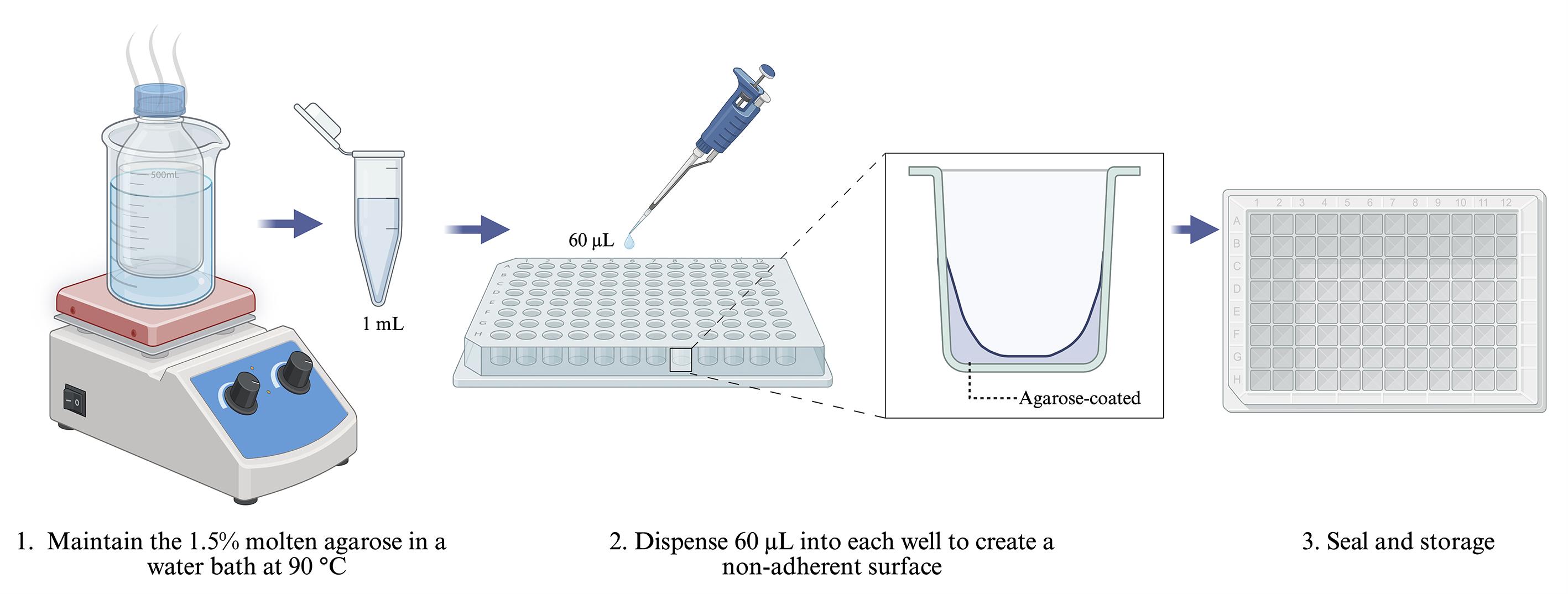
Figure 1. Preparation of cost-effective, non-adherent plates using agarose coating
5. Refresh the aliquot if necessary. Repeat the dispensing step until all required wells are filled. If the agarose in the working aliquot begins to solidify, replace it with fresh molten agarose from the main stock.
6. Solidify and dry. Allow the agarose to solidify undisturbed at room temperature. Once solid, leave the plate uncovered in a cell culture hood for 15 min to allow residual moisture to evaporate under laminar flow.
7. Seal the plate. Wrap it tightly with clean plastic film (e.g., Parafilm) and place it inside a sealed plastic bag to prevent dehydration and contamination.
8. Keep the coated plates at 4 °C. Under these storage conditions, they remain usable for 2–3 weeks.
B. Thawing MDA-MB-231 cells
1. Remove the cryovial of MDA-MB-231 cells from liquid nitrogen.
2. Warm it immediately in a 37 °C water bath, swirling gently until completely thawed (approximately 1–2 min).
3. Inside a biosafety cabinet, use a sterile 2 mL serological pipette to transfer the thawed cells into a sterile 1.5 mL tube.
4. Centrifuge the tube at 257× g for 5 min at room temperature to form a cell pellet.
5. Carefully remove the supernatant with a sterile 2 mL serological pipette, avoiding disturbance to the pellet.
6. Gently resuspend the pellet in 1 mL of prewarmed supplemented DMEM by pipetting up and down.
7. Transfer the suspension to a 60 mm × 15 mm culture dish, then add 4 mL of supplemented DMEM.
8. Gently rock the dish in a crosswise pattern to evenly distribute the cells, then place it in a 37 °C, 5% CO2 humidified incubator.
C. Subculture and preparation of MDA-MB-231 cells
1. Grow MDA-MB-231 cells in 60 mm dishes with supplemented DMEM at 37 °C, 5% CO2 until they reach about 80% confluence, which typically occurs within 3 days.
2. Aspirate the old culture medium with a sterile serological pipette.
3. Gently rinse the cells with 5 mL of sterile 1× PBS to remove any remaining serum (which can inhibit trypsin). Then, aspirate the PBS.
4. Add 3 mL of warm 0.04% trypsin-EDTA, ensuring it covers the entire cell layer.
5. Let the dish sit at 37 °C for 3–5 min. Check under a microscope periodically; cells are ready when they appear round and begin floating.
6. Add 6 mL of supplemented DMEM (the serum inhibits the trypsin).
7. Gently pipette up and down to break up clumps, then transfer the entire suspension into a sterile 15 mL conical tube.
8. Spin at 257× g for 5 min at room temperature.
9. Carefully remove the supernatant without disturbing the cell pellet.
10. Add 1 mL of fresh supplemented DMEM and gently pipette to resuspend the pellet.
11. Count the cells prior to experimental use or passaging. The expected density is approximately 3 × 10⁶ cells/mL.
Note: After thawing, pass cells at least three times before experiments to allow them to recover and grow steadily.
D. Cell counting with a Neubauer chamber (Figure 2)
1. Prepare a 1:10 dilution of your cell suspension:
a. Add 90 μL of supplemented DMEM medium to a sterile 1.5 mL microcentrifuge tube.
b. Add 10 μL of the well-mixed cell suspension to the same tube.
c. Mix gently by pipetting.
2. Load the hemocytometer: Draw 10 μL of the diluted suspension into the chamber of a Neubauer hemocytometer. Allow the liquid to fill the chamber by capillary action. The chamber should be fully covered but not overflowing.
3. Count the cells:
a. Place the hemocytometer under an inverted microscope.
b. Count the cells in each of the four corner squares (each contains 16 small squares).
Rule: Include cells touching the top and left edges. Exclude cells touching the bottom and right edges.
4. Calculate the concentration (cells/mL):
a. Average the counts from the four corner squares.
b. Multiply by 10,000 (hemocytometer conversion factor).
c. Multiply by 10 (dilution factor).
Formula:
Example calculation:
Note: A density of 2.5–3.0 × 10⁶ cells/mL is considered optimal.
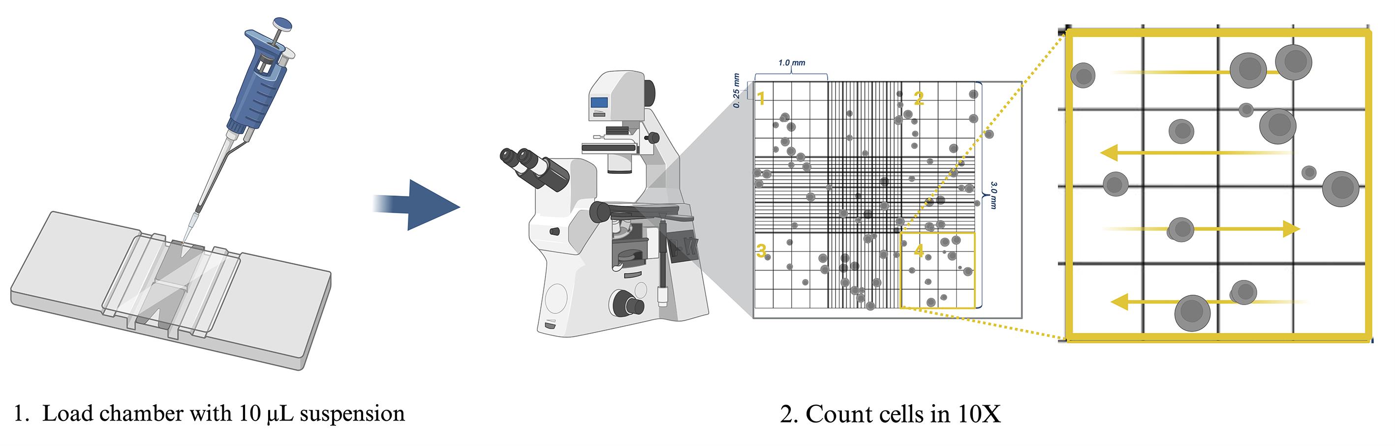
Figure 2. Cell counting with the Neubauer chamber
E. Spheroid formation (Figure 3)
1. Grow cells in a monolayer. Maintain cells in standard 2D culture conditions (37 °C, 5% CO2) until they reach the desired confluency.
2. Prepare the cell suspension. Resuspend the cells in supplemented DMEM medium to a final density of 20,000 cells per 100 μL.
3. Seed the non-adherent plate. Add 100 μL of the cell suspension to each well of the NA plate.
4. Promote aggregation. Place the plate on an orbital shaker set to 150 rpm for 3 h at room temperature to encourage cell clumping.
Note: Perform the shaking step inside a standard 37 °C, 5% CO2 incubator, if equipment permits.
5. Incubate to form spheroids. Transfer the plate to a humidified incubator at 37 °C with 5% CO2 and leave it undisturbed for 96 h.
6. Maintain the culture. Every 48 h, replace half of the medium in each well, taking care not to disrupt the developing spheroids. To do so, 100 μL of spent medium is carefully aspirated from each well, such that the forming spheroid at the bottom is not disturbed, and 100 μL of fresh, prewarmed supplemented DMEM is gently added along the wall of the well.
7. Verify spheroid formation. Examine the wells under an inverted microscope. Successful formation is indicated by the presence of compact, spherical aggregates.
Note: We recommend a minimum of 12 spheroids per experimental condition. To ensure a sufficient yield of high-quality histological sections, embed 36 spheroids per paraffin block.
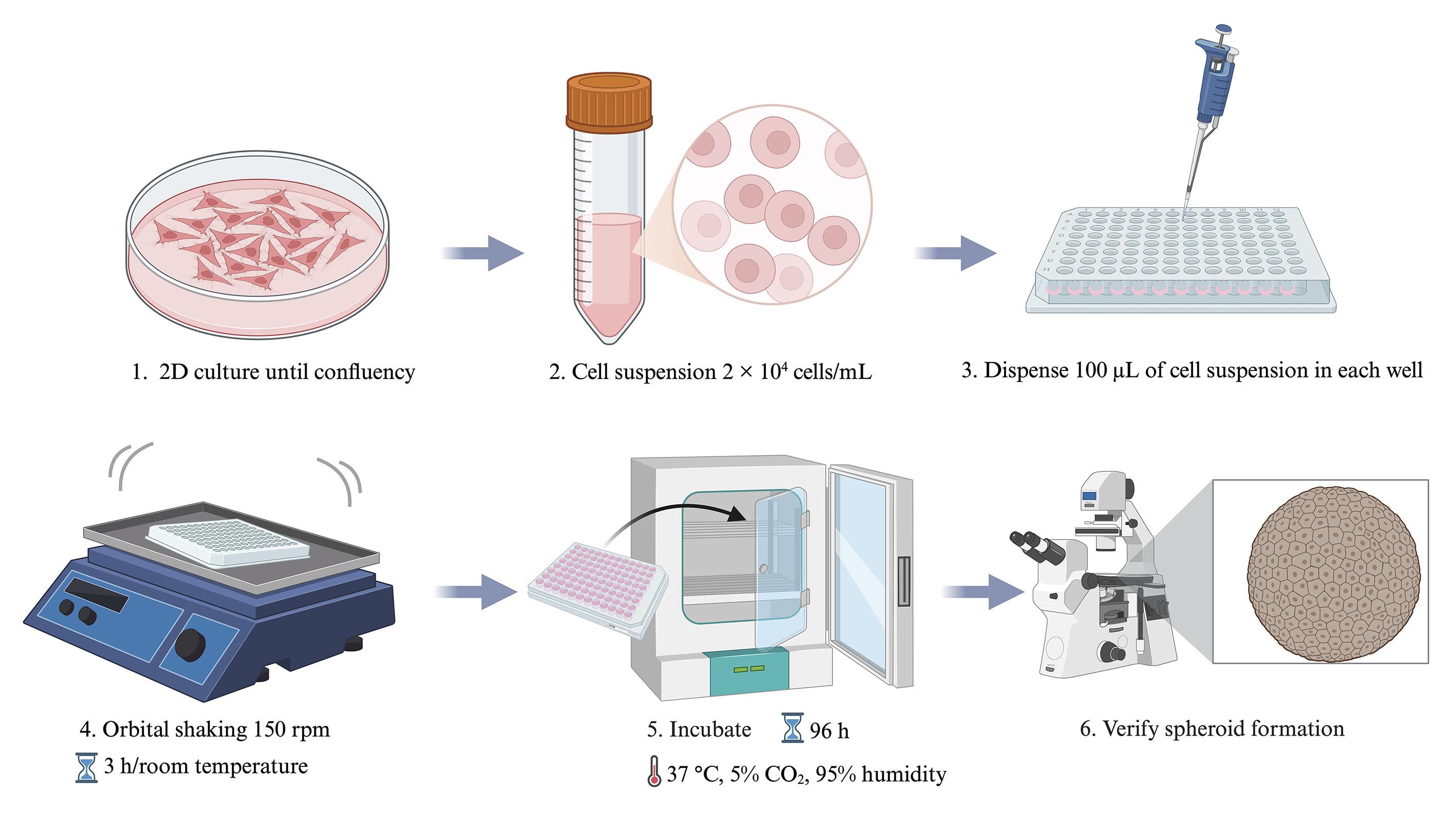
Figure 3. Formation of spheroids in non-adherent plates
F. Spheroid fixation (Figure 4)
1. After spheroid formation is complete, carefully transfer the spheroids into a sterile 1.5 mL microcentrifuge tube using a 1,000 μL pipette.
2. Centrifuge at 257× g for 5 min at room temperature to gently pellet the spheroids.
3. Carefully remove the supernatant without disturbing the pellet.
4. Add 50 μL of buffered formalin to completely cover the spheroids.
5. Incubate at room temperature until further downstream processing (at least 24 h).
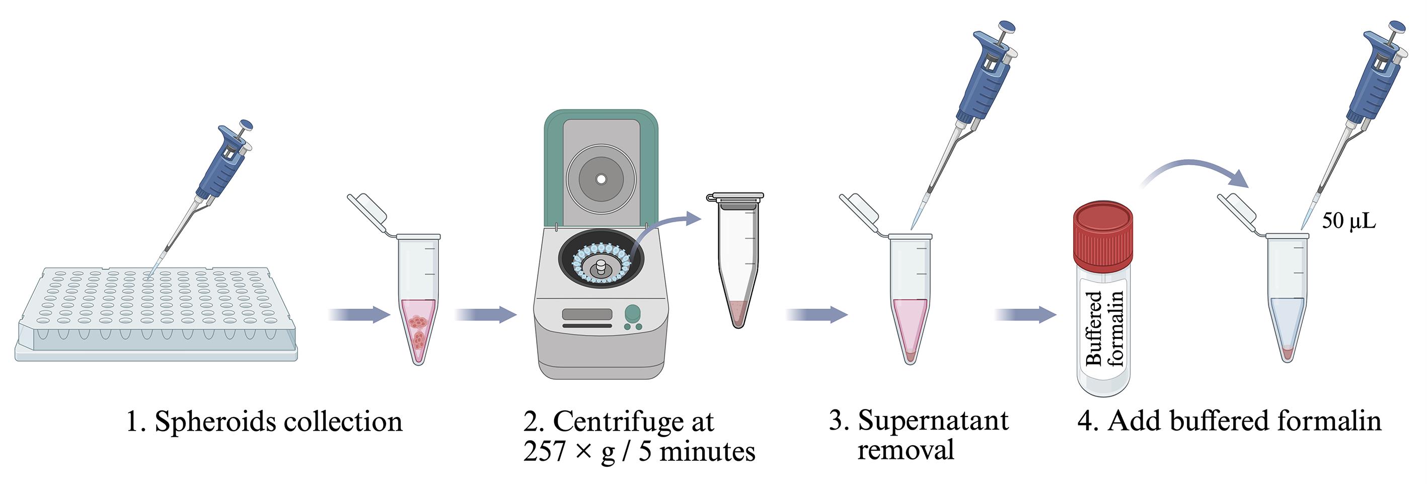
Figure 4. Fixation of spheroids in buffered formalin before downstream processing
G. Dehydration of fixed spheroids (Figure 5)
Note: After fixation, samples should be dehydrated using a graded ethanol series to eliminate water, preparing them for clearing and subsequent embedding. Perform all steps at room temperature. Using a 1,000 μL micropipette, carefully aspirate each solution while ensuring that the spheroids remain undisturbed at the bottom of the tube. To this end, leave a small residual volume of the solution rather than aspirating completely to dryness.
1. Replace the fixative with 70% ethanol. Carefully remove the buffered formalin from the tube containing the fixed spheroids, taking care not to aspirate the pellet. Add 50 μL (or sufficient volume to fully immerse the spheroids) of 70% ethanol. Incubate for 60 min at room temperature (repeat twice).
2. Replace with 80% ethanol. Remove the 70% ethanol and add 50 μL of 80% ethanol. Incubate for another 60 min at room temperature (repeat twice).
3. Replace with 96% ethanol. Remove the 80% ethanol and add 50 μL of 96% ethanol. Incubate for a final 60 min.
4. Replace with 100% ethanol. Remove the 96% ethanol and add 50 μL of 100% ethanol. Incubate for a total of 60 min. This step removes most of the remaining water from the samples.
5. Clear the samples with xylene. Remove the 100% ethanol and add 50 μL of xylene, or enough to cover the spheroids. Xylene replaces the ethanol, making the spheroids transparent and ready for paraffin infiltration. Incubate at room temperature for 60 min. Avoid extending xylene exposure beyond the necessary time to prevent excessive hardening of the sample.
Note: For delicate spheroids, reduce incubation times to 30 min per ethanol step to minimize shrinkage. Always perform xylene clearing in a chemical fume hood due to its toxicity. Delicate spheroids are defined as those that are either very small in size or exhibit poor structural compaction, making them particularly prone to mechanical damage during handling and processing.
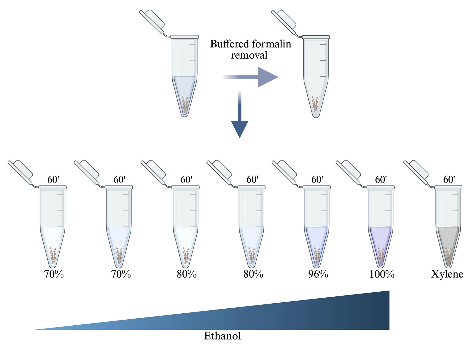
Figure 5. Dehydration and clearing of fixed spheroids for paraffin infiltration
H. Paraffin infiltration and embedding of samples (Figure 6)
Note: After dehydration and clearing, samples must be infiltrated with molten paraffin and embedded in blocks to provide structural support for microtomy. Perform all steps in a well-ventilated area or in a fume hood if using fresh paraffin containing volatile additives. Use a paraffin oven or bath set to exactly 65 °C.
1. Transfer samples into molten paraffin at 65 °C using a 1.5 mL tube with a floating support. Spheroids are too small to handle individually; use a floating system to support the 1.5 mL tube during infiltration in the paraffin bath.
a. Transfer the xylene-cleared spheroids into a 1.5 mL tube. Residual xylene carried over will evaporate during the subsequent heating step and does not require removal. Then, fill the tube completely with molten paraffin (65 °C) to fully immerse the spheroids.
b. Float the 1.5 mL tube in a 65 °C paraffin bath so that the paraffin inside remains molten.
c. Ensure the tube is stable.
2. Allow infiltration overnight (~24 h). Keep the floating 1.5 mL tube in the 65 °C paraffin bath for approximately 24 h. Do not exceed 65 °C, as higher temperatures may damage the spheroids' morphology.
3. Remove samples and place them on a cold plate to make handling easier. Using prewarmed forceps, lift the 1.5 mL tube from the paraffin bath. Insert the forceps into the tube, then immediately transfer it to a cold plate (surface temperature -10 °C to 4 °C). Leave it on the cold plate for 10–20 min to let the paraffin solidify. If a cold plate is unavailable, use an ice block.
4. Transfer to embedding molds with fresh paraffin.
a. Once the paraffin has solidified, carefully lift the forceps to remove the plug. Make sure the bottom part, where the spheroids are concentrated, comes out first. The spheroids will be located at the bottom of the 1.5 mL tube.
b. Using a cutter, cut off the bottom portion of the paraffin plug that comes out of the tube; this is where the spheroids are concentrated.
c. Place the cut piece into an embedding mold, then add fresh molten paraffin at 65 °C to embed the spheroids.
d. Insert the plug into a standard embedding mold filled with fresh molten paraffin at 65 °C, with the spheroid-rich end facing the intended cutting surface.
e. Add more fresh molten paraffin to completely fill the mold.
f. Use warm forceps or needles to adjust orientation if needed. Always use fresh paraffin for this final embedding to avoid contamination.
5. Allow blocks to solidify at -10 °C. Place the filled molds on a level surface in a freezer or on a cold plate set to -10 °C. Solidify for 15–30 min, depending on mold size. Rapid cooling to -10 °C produces fine, uniform paraffin crystals, improving sectioning quality. Avoid slow cooling (e.g., at 4 °C), which leads to large crystals that tear sections. After full solidification, remove the paraffin block from the mold-flex plastic molds or briefly warm metal molds.
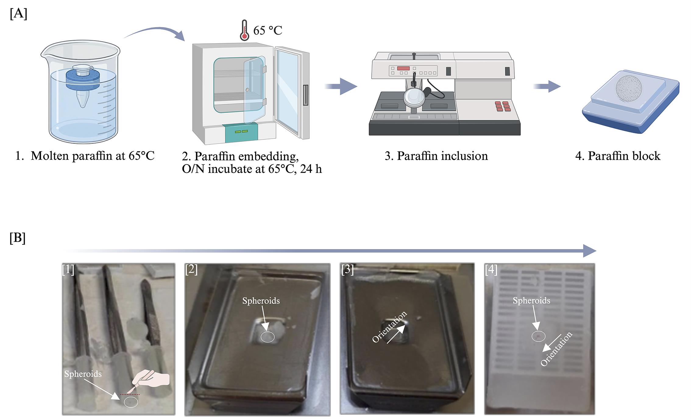
Figure 6. Paraffin embedding of spheroids using a 1.5 mL tube floating system. (A) Schematic representation of the paraffin embedding workflow. (B) Retrieval of the embedded specimen from a 1.5 mL microtube, using forceps to stabilize the paraffin block. Steps 1–4 illustrate the embedding process: (1) solidification of paraffin in a cold block with forceps in place; (2) removal of the solidified paraffin plug from the tube, followed by trimming of the tip containing the spheroids; (3) transfer of the trimmed tip to fresh molten paraffin at 65 °C; and (4) final embedding of the spheroids in a paraffin block.
I. Sectioning of paraffin blocks (Figure 7)
Note: After embedding, paraffin blocks must be sectioned to obtain thin ribbons of spheroids for mounting and subsequent staining. Use a rotary microtome and clean glass slides and perform all steps at room temperature.
1. Mount the paraffin block in the microtome. Trim the excess paraffin around the tissue (spheroid-containing area) using a scalpel, leaving a clean block face with the sample fully exposed. Clamp the block securely into the microtome block holder, ensuring the cutting surface is parallel to the blade. Orient the block so that the spheroids will be sectioned at the desired plane, and use a fresh, sharp disposable microtome blade to prevent tearing or compression.
2. Cut sections at 4-μm thickness. Set the microtome to cut at 4 μm, advance the block slowly, and discard the first few sections until the full face of the spheroids is exposed. Cut at a steady, moderate speed, approximately 1–2 sections per second, and collect a ribbon of 5–10 serial sections. If sections curl or wrinkle, adjust the blade clearance angle. For brittle spheroids, chill the block on ice for 5–10 min before cutting.
3. Float sections in a 40 °C water bath. Fill a flotation water bath with distilled water and heat it exactly to 40 °C. Use fine forceps or a paintbrush to gently place the cut ribbon (or individual sections) on the water surface, with the shiny side (the original block face) facing down. Let the sections flatten completely, which usually takes 5–15 s; avoid floating them for more than 1 min, as this can cause the tissue to expand or become disrupted. If needed, a brush can be used to carefully separate individual sections.
4. Collect sections onto glass slides. Use clean, positively charged glass slides to improve tissue adherence. Gently dip the slide into the water bath at a slight angle, catching one section per slide or multiple sections per slide as desired. Lift the slide vertically to pick up the section, taking care not to trap air bubbles beneath it. For serial sections, collect consecutive sections onto separate slides or arrange them in order on a single slide.
5. Dry slides at room temperature or at 40 °C. For room-temperature drying, leave them overnight (12–24 h) in a dust-free environment. For drying at 40 °C, place the slides on a slide warmer or in a forced-air incubator for 1–2 h. Ensure sections are completely dry before staining or storage, as incomplete drying may cause them to detach during subsequent staining steps.
Notes:
1. For small spheroids, carefully trim the block to avoid cutting too deeply past the sample. Clean the water bath daily to prevent contamination. Store dried slides in a closed slide box at room temperature, protected from dust and moisture. If sections wrinkle repeatedly, add a drop of 0.1% gelatin or a commercial adhesive to the water bath.
2. Owing to their small size, spheroids typically yield 8-10 serial sections of 4-μm thickness. The central sections are the most informative, as they encompass the entire spheroid architecture and allow for clear morphological assessment. These sections are therefore best suited for evaluating treatment effects; as a result, only 2–3 sections of optimal quality are generally recovered per spheroid. The embedded spheroids are readily identifiable as small, opaque dots on the block face, which facilitates precise orientation during microtomy.
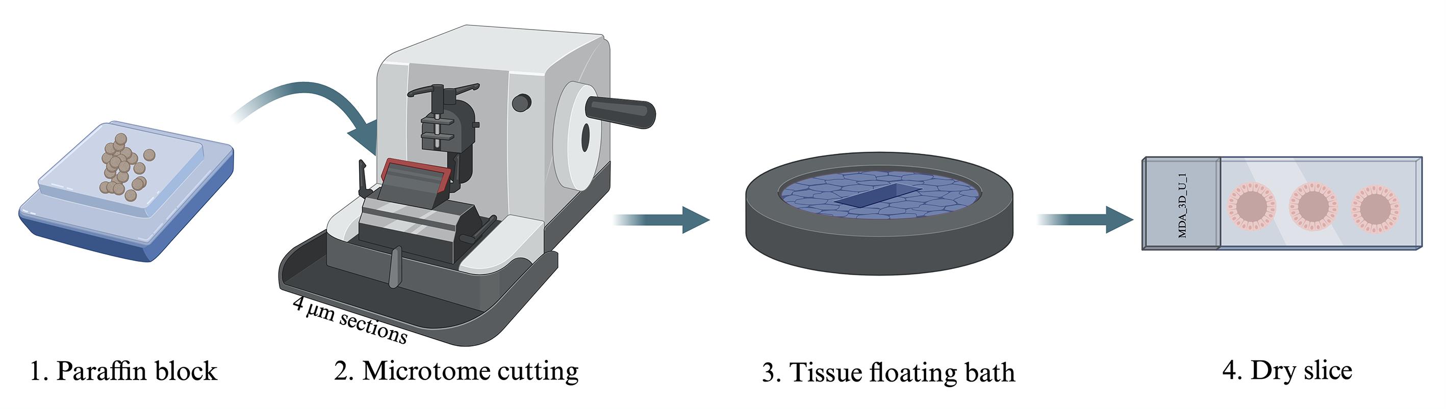
Figure 7. Microtome sectioning of paraffin-embedded spheroids
J. Hematoxylin and eosin (H&E) staining (Figure 8)
Note: After sectioning and drying, slides must be stained to visualize nuclear and cytoplasmic details. Perform all steps at room temperature in a fume hood when using xylene. Use fresh solutions and change them according to the laboratory schedule.
1. Heat the slides at 100 °C for 5 min to melt the paraffin and firmly adhere the sections to the glass. Place the slides on a slide warmer or in a preheated oven, ensuring they are level to prevent sections from running off.
2. Immerse the slides in xylene three times for 5 min each. Xylene removes all remaining paraffin. Use a clean xylene bath for each immersion, and gently agitate the slides periodically to ensure effective deparaffinization.
3. Transfer the slides to 96% ethanol for three 3-min changes. This step gradually replaces xylene with alcohol, rehydrating the tissue.
4. Immerse the slides in 80% ethanol for 3 min to continue the graded rehydration.
5. Immerse the slides in 70% ethanol for 3 min to bring the sections to a lower alcohol concentration.
6. Rinse the slides briefly in distilled water to remove ethanol and prepare the tissue for aqueous staining solutions. Use a gentle stream or a dip in a clean water bath.
7. Immerse the slides in hematoxylin solution for 7 min. Hematoxylin stains cell nuclei a deep blue-purple. Use standard hematoxylin. Ensure the slides are fully submerged and not touching each other.
8. Rinse the slides in distilled water to remove excess hematoxylin. A single gentle rinse is usually sufficient; avoid over-rinsing, which may wash out the stain.
9. Dip the slides in acid alcohol with three quick immersions. Differentiation removes excess hematoxylin from the cytoplasm and connective tissue, leaving nuclei sharply stained. Do not leave slides in acid alcohol for more than a few seconds.
10. Immerse the slides in lithium carbonate solution (a weak alkaline solution, usually 0.1%–0.5% lithium carbonate in water) for a few seconds. This step “blues” the hematoxylin, converting it from a red-brown to a blue-purple color.
11. Rinse the slides in distilled water to remove residual lithium carbonate.
12. Immerse the slides in 70% ethanol for 1 min to re-equilibrate the tissue before eosin staining.
13. Immerse the slides in eosin solution for 10 min. Eosin stains cytoplasmic components pink to orange. Use an alcoholic or aqueous eosin as preferred.
14. Transfer the slides to 80% ethanol for 3 min to begin removing water and excess eosin.
15. Immerse the slides in 96% ethanol for three changes of 3 min each. Complete dehydration is essential for proper clearing.
16. Immerse the slides in xylene for two changes of 5 min each. Xylene replaces ethanol, making the sections transparent and ready for mounting.
17. Air-dry the slides in a fume hood for 5–10 min, or until no traces of xylene remain. Do not let the sections become completely dry before mounting, as this can cause cracking. Alternatively, mount immediately from the last xylene bath using a resinous mounting medium.
Note: Always wear appropriate personal protective equipment (gloves, lab coat, safety glasses) when handling xylene, acid alcohol, and lithium carbonate. If background staining is too dark, shorten the eosin step or extend differentiation. Store stained slides in a dust-free slide box after coverslipping.
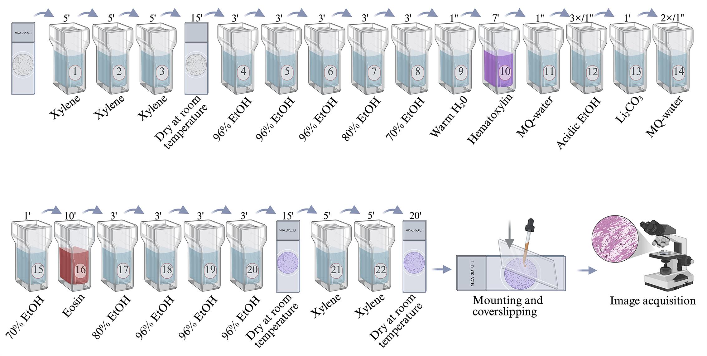
Figure 8. Spheroid sections stained with hematoxylin and eosin (H&E) and coverslipped
K. Mounting and coverslipping of stained sections (Figure 8)
Note: After clearing, slides must be coverslipped with a resinous mounting medium to preserve the stained sections for long-term storage and microscopic examination. Perform this step immediately after the final xylene bath to prevent the sections from drying out and crystallizing.
1. Apply mounting resin immediately after the last xylene step. Do not let the slides air-dry completely, as dried sections become brittle and hard to cover without air bubbles. Remove the slide from xylene, drain excess solution by touching the edge to a paper towel, and work quickly.
2. Add one drop of mounting resin directly onto the section. Use a clear, xylene-based resin. The drop should be just large enough to spread under the coverslip without overflowing. Avoid using too much resin, which can seep out and become sticky.
3. Place a clean glass coverslip carefully over the drop. Lower the coverslip at a slight angle (approximately 45°) using fine forceps or a needle, allowing the resin to spread evenly without trapping air bubbles (Figure 8). Gently press the coverslip down with the back of the forceps to expel any small bubbles and ensure uniform coverage.
4. Allow the mounted slides to dry at room temperature in a horizontal position for 24–48 h. Protect the slides from dust during drying by placing them in a covered slide box or under a dust cover. Once fully hardened, slides can be stored upright in a slide box at room temperature.
Note: Always work in a fume hood when using xylene-based mounting resins. Clean any excess resin from the edges of the coverslip with a lint-free tissue moistened with xylene. For faster drying, slides can be placed on a slide warmer at 37 °C for 2–4 h, but room-temperature curing results in a more durable mount.
L. Image acquisition
Note: After mounting and drying, slides should be examined and photographed to record staining results. Use an inverted microscope equipped with a digital camera and suitable brightfield optics. Conduct all imaging under consistent lighting and magnification for each experimental condition.
1. Acquire images with an inverted microscope equipped with a digital camera (Figure 8). Place the slide on the stage with the coverslip facing the objective lens. Begin with low magnification (e.g., 4× or 10×) to locate spheroids or regions of interest, then switch to higher magnification (e.g., 20× or 40×) for detailed observation (Figures 9 and 10). Adjust the focus, brightness, and contrast to produce a clear, evenly illuminated image. Use the same exposure time and white balance settings for all samples to ensure consistency.
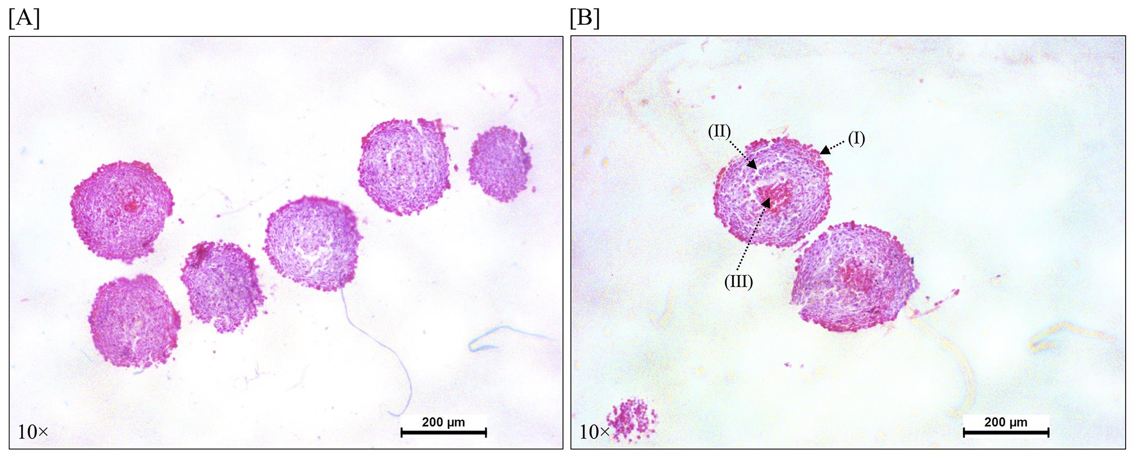
Figure 9. Histological analysis of MDA-MB-231 spheroids stained with hematoxylin and eosin (H&E). (A) Representative serial sections from a single spheroid (10× magnification), showing internal structural consistency. (B) 10× magnification view highlighting the characteristic zonal architecture of a mature spheroid, clearly delineating the peripheral (I), intermediate (II), and central (III) regions.
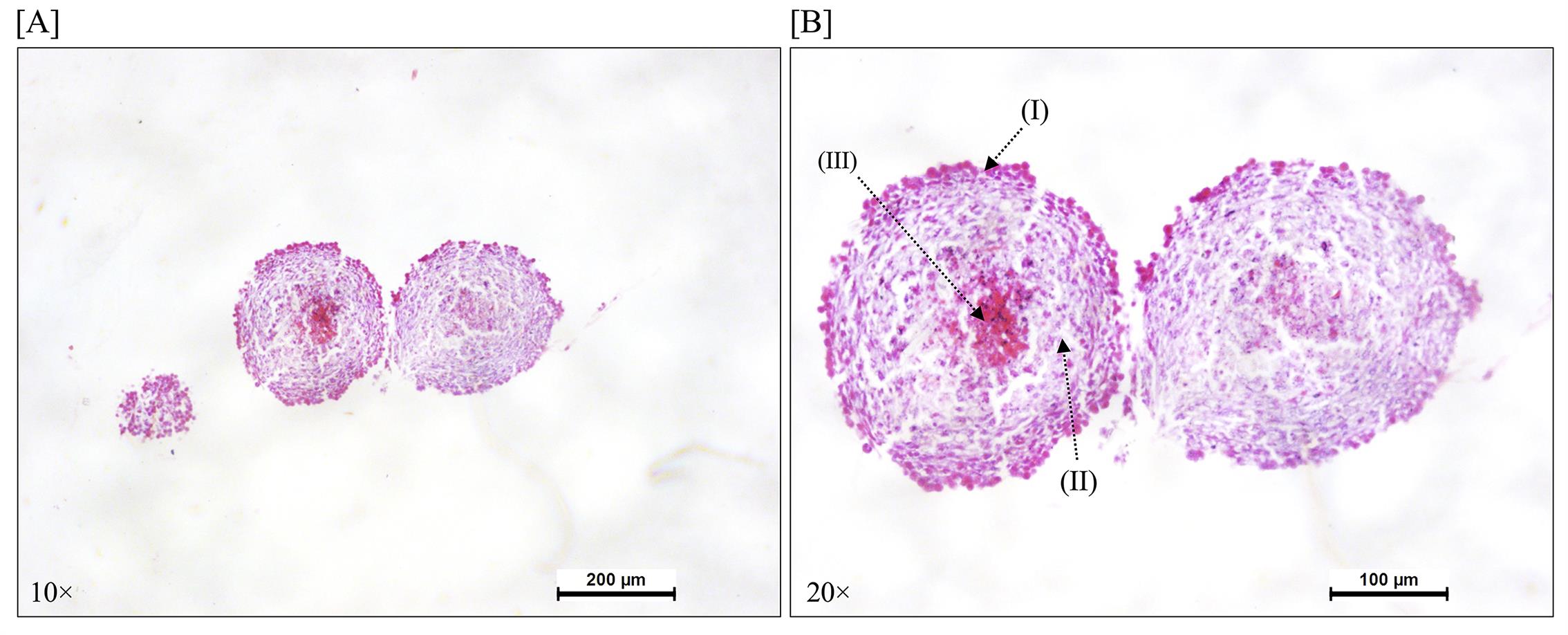
Figure 10. Sections of a mature MDA-MB-231 spheroid stained with hematoxylin and eosin (H&E). (A) Representative sections showing the typical spheroid structure (10× magnification). (B) A 20× magnification view emphasizing the distinctive zonal architecture of a mature spheroid, clearly illustrating the peripheral (I), intermediate (II), and central (III) regions.
2. Capture representative images for each experimental condition. For each condition (such as control, treated, or various time points), take at least 3–5 images from non-overlapping fields. Include images at low magnification to display overall spheroid morphology and at high magnification to detail nuclear and cytoplasmic staining. Save images in an uncompressed format (like TIFF) with a consistent naming convention that includes the date, sample identifier, condition, and magnification.
Note: Calibrate the microscope with a stage micrometer before acquisition if you plan to perform quantitative measurements like spheroid diameter or staining intensity. Avoid overexposure to prevent bleaching of eosin signals and use a clean objective lens for each session. Organize image files in a structured folder system and keep a backup copy.
M. Treatment of spheroids with actinomycin D
1. Following confirmation of spheroid formation, slowly add 200 μL of prewarmed non-supplemented DMEM along the inner wall of each well to prevent spheroid displacement.
2. Aspirate 200 μL of medium from each well, leaving a constant residual volume of 100 μL per well at all times.
3. Prepare 2× working solutions of actinomycin D in non-supplemented DMEM to achieve the desired final concentrations. For example, to obtain a final concentration of 10 μM, prepare a 20 μM working solution.
4. Gently dispense 100 μL of the appropriate 2× actinomycin D working solution along the well wall of each corresponding well. This brings the total volume to 200 μL and establishes the final drug concentration.
5. In each experiment, include the following control groups:
a. Untreated control: spheroids maintained in non-supplemented DMEM only (no drug).
b. Vehicle control: spheroids incubated with non-supplemented DMEM containing the equivalent volume of DMSO used to dissolve actinomycin D (final concentration: 0.05% DMSO, the maximum non-cytotoxic concentration determined for this assay).
Validation of protocol
Morphological and histological evaluation of actinomycin D efficacy in MDA-MB-231 spheroids
Spheroids derived from the MDA-MB-231 cell line are a well-established, physiologically relevant preclinical model in cancer research. This cell line originated from a triple-negative breast cancer (TNBC) patient, characterized by the absence of estrogen receptor (ER), progesterone receptor (PR), and HER2 amplification, making it inherently resistant to conventional hormone- and HER2-targeted therapies. As a result, MDA-MB-231 spheroids serve as a valuable platform for testing new anti-cancer compounds and understanding their mechanisms of action in conditions that more closely mimic the tumor microenvironment than standard monolayer cultures.
The morphological assessment of compound-treated spheroids serves two main purposes: it offers an initial indication of cytotoxic effectiveness while also providing indirect evidence of drug penetration into the 3D architecture. A compound that does not diffuse beyond the outer cell layers usually causes surface damage without affecting the core, whereas an effective penetrant compound induces structural changes throughout the entire spheroid. In this context, treatment with actinomycin D, a powerful transcription inhibitor and well-known chemotherapeutic agent, produced clear phenotypic changes in MDA-MB-231 spheroids. Treated cultures showed a reduction in overall spheroid diameter, along with a gradual loss of the typical compact, round morphology (Figure 11). Additionally, the appearance of many rounded, highly refractile (phase-bright) bodies at the spheroid edges and in the surrounding medium-morphologically similar to apoptotic cells-provided clear visual evidence of extensive programmed cell death. Taken together, these observations confirm that actinomycin D effectively penetrates the 3D structure and exerts strong cytotoxic activity against this aggressive TNBC model, supporting its use as a positive control or reference compound in future spheroid experiments.
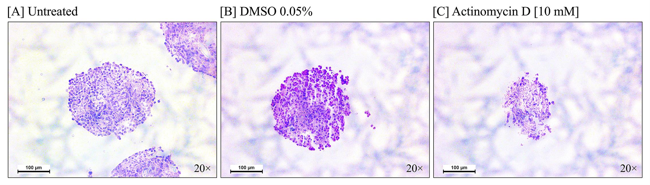
Figure 11. Morphological effects of actinomycin D on MDA-MB-231 spheroids. Representative histological hematoxylin-eosin stain images of spheroids under three conditions: (A) Untreated control, showing typical compact and rounded morphology; (B) vehicle control (DMSO 0.05%), confirming no solvent-induced effects on spheroid integrity; and (C) actinomycin D (10 μM) for 48 h, showing noticeable changes in spheroid size and structural organization.
Histological evaluation of actinomycin D-induced cytotoxicity in A549 spheroids
The A549 cell line, derived from human lung adenocarcinoma, is one of the most widely used models in non-small cell lung cancer research. Its extensive use is due to its well-documented genetic background and predictable behavior in both 2D and 3D culture systems. When grown under non-adherent conditions, A549 cells naturally form cohesive, relatively compact spheroids with well-defined, smooth borders and consistent size distribution. This high level of reproducibility makes A549 spheroids an excellent platform for high-throughput drug screening, allowing for reliable quantitative assessments of compound effectiveness across multiple experimental runs.
Morphological evaluation of treated spheroids provides critical insights that extend beyond simple cytotoxicity. Specifically, the degree and pattern of structural disruption serve as a surrogate marker for drug penetration capacity: compounds that fail to reach the inner layers typically cause surface erosion without compromising the core, whereas agents with favorable diffusivity induce global architectural destabilization. Exposure of A549 spheroids to actinomycin D produced striking phenotypic changes (Figure 12). Treated cultures displayed a substantial and progressive reduction in spheroid diameter, accompanied by progressive loss of surface smoothness and overall structural compaction.
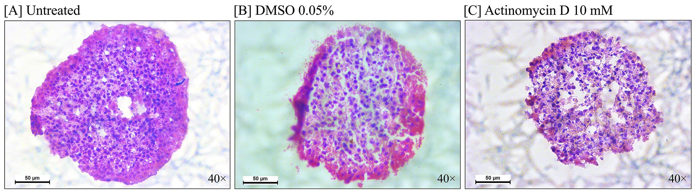
Figure 12. Actinomycin D disrupts A549 spheroid morphology and induces apoptosis. Representative histological hematoxylin-eosin stain images of A549 lung carcinoma spheroids under three experimental conditions: (A) Untreated control, showing a dense, compact, and well-rounded shape with smooth borders; (B) vehicle control (DMSO 0.05%), confirming that the solvent does not affect spheroid integrity or structure; and (C) actinomycin D (10 μM). Treated spheroids display a structural breakdown, including decreased size, loss of cohesion, surface irregularities, and extensive cellular detachment from the spheroid edges.
Visualizing actinomycin D-induced structural alterations in Caco-2 spheroids through histology
The Caco-2 cell line, originally derived from a human colorectal adenocarcinoma, is widely used in pharmaceutical research, especially for studying intestinal permeability and drug transport mechanisms. However, when cultured under non-adherent conditions to form 3D spheroids, Caco-2 cells pose a distinct morphological challenge: unlike the compact, uniformly rounded aggregates seen in breast or lung carcinoma models, Caco-2 cells naturally form looser, irregularly shaped, and structurally diverse assemblies with poorly defined borders and variable cell-cell adhesion. This inherent fragility makes whole-mount brightfield assessment difficult, as baseline morphological variability can hide subtle treatment-related changes. Therefore, establishing a robust histological pipeline-including careful retrieval, formalin fixation, paraffin embedding, and serial H&E sectioning-is especially important for this model. Sectioning enables standardized, high-resolution visualization of internal cytoarchitecture, effectively overcoming limitations imposed by surface-level heterogeneity.
At the 48-h mark, actinomycin D treatment (10 μM) already causes easily detectable cytopathic effects that exceed the natural variability of untreated cultures. Histological examination of control spheroids, both untreated and vehicle-treated, shows loosely cohesive cell clusters with scattered intercellular spaces, consistent with the characteristic phenotype of this line. In sharp contrast, samples exposed to actinomycin D display architectural erosion, marked by widespread cellular dissociation, loss of intercellular contacts, and the development of large acellular zones within the aggregate matrix (Figure 13). Additionally, H&E-stained sections prominently feature numerous condensed, hyperchromatic nuclei alongside fragmented eosinophilic cytoplasmic remnants, indicating active apoptosis, throughout the remaining cellular mass. Overall, this histological analysis confirms the compound's strong anti-tumor activity even in challenging, less compact 3D structures, while also showing that Caco-2 spheroids are suitable for screening drugs targeting colorectal cancers, as long as appropriate histological endpoints are used.
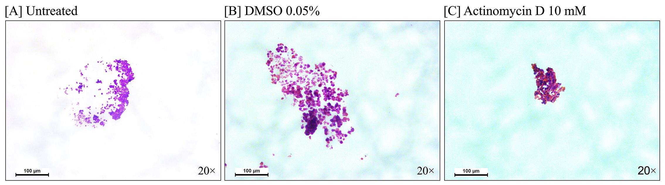
Figure 13. Actinomycin D causes cytotoxic disassembly of Caco-2 spheroids. Representative histological hematoxylin-eosin stain micrographs of CaCo-2 colorectal spheroids taken 48 h after treatment. (A) Untreated cultures and (B) vehicle controls (DMSO 0.05%) both show the characteristic loose, granular structure typical of this cell line, with minimal background cellular debris. (C) The addition of actinomycin D (10 μM) induces a clear phenotypic change: the spheroid matrix visibly collapses, along with extensive shedding of membrane-blebbed remnants and highly condensed apoptotic figures. Notably, despite the naturally limited compaction of CaCo-2 spheroids, the cytotoxic signature remains unequivocally distinguishable from the basal state.
To contextualize the novelty of our approach, we compared our tube-based protocol with the most relevant previously published methods (Table 1). This comparison highlights that, unlike existing protocols that require specialized equipment [9], agarose pre-embedding [14], matrix handling [14], or multiple sample transfers [8], our method enables complete in-tube processing using only standard laboratory equipment. This integration minimizes sample loss, facilitates consistent orientation, and provides a robust workflow for fragile spheroids across multiple cell lines. While our validation is limited to cell line-derived spheroids, the protocol’s simplicity and accessibility make it a practical alternative for laboratories seeking routine histological analysis of 3D spheroid models.
Table 1. Comparative analysis of key methodological features between the proposed tube-based protocol and previously published spheroid processing methods.
| Feature | This protocol | Yoshimoto et al. [8] | Gabriel et al. [9] | Moraes et al. [10] | Guyon & Daubon [7] | Mondal et al. [13] |
| Core innovation | Complete in-tube processing from fixation to embedding using a standard 1.5 mL microcentrifuge tube and a floating system for paraffin infiltration. | Optimized protocol for paraffin embedding of spheroids. | Microarray approach for parallel embedding and sectioning of large spheroid sample sets. | Agarose apparatus for organized, simultaneous histological processing of multiple spheroids. | Protocol for embedding spheroids invading a 3D collagen matrix into paraffin molds. | Protocol for spheroid generation, immunolabeling, and high-quality imaging. |
| Sample type | Cell line-derived spheroids (MDA-MB-231, A549, Caco-2). | Spheroids and organoids. | 3D cell spheroids. | 3D cancer cell spheroids. | Invasive glioblastoma organoids in 3D collagen. | 3D tumor spheroids. |
| Equipment and complexity | Low-cost, accessible. Uses only standard lab equipment (centrifuge, water bath, microtome) and a 1.5 mL tube. | Standard laboratory equipment. | Requires a custom-fabricated Teflon grid for the microarray. | Uses a simple, low-cost agarose apparatus. | Requires handling of 3D collagen matrices and specific steps for paraffinization. | Standard equipment for spheroid culture and imaging. |
| Key advantage | Minimizes sample loss and damage by eliminating multiple sample transfers. | Reproducible FFPE sections for spheroids and organoids. | Enables high-throughput, parallel analysis of up to 96 spheroids. | Allows high-throughput, organized analysis of several spheroids in one block. | Allows histological identification of markers in invasive cells escaping the tumor. | Provides guidance for optimal immunostaining and imaging to study 3D protein localization. |
| Limitation/considerations | Validation limited to cell lines. Not yet tested with organoids or primary tissue. | Potential sample loss during multiple processing steps. Requires transfer between vessels. | Requires specialized equipment (custom grid) not standard in all labs. | Relies on pre-embedding in an agarose apparatus, adding an extra handling step. | Specifically designed for matrix-embedded samples; requires additional steps for matrix handling. | Focuses on imaging, not optimized for routine paraffin histology or H&E. |
General notes and troubleshooting
| Problem | Possible cause(s) | Solution(s) |
| Spheroids disintegrate during fixation | Excessive pipetting or vortexing; formalin exposure too short. | Use wide-bore pipette tips; increase fixation time to 48-72 h; centrifuge at lower speed (200× g). |
| Inability to visualize spheroid pellet after centrifugation | Pellet too small or translucent; insufficient centrifugation speed; tube not properly oriented. | Stain with a trace of neutral red or use a colored marker on the tube exterior to mark the expected pellet position; increase centrifugation to 300× g for 5 min; use a black marker to dot the tube at the bottom for reference. |
| Spheroids lost during dehydration | Incomplete pellet formation; aspirating too close to the pellet. | Centrifuge at 257× g for 5 min; leave 10–20 μL of supernatant above the pellet; use a gel-loading tip for removal. |
| Xylene carryover during paraffin infiltration | Residual xylene not fully evaporated; incomplete paraffin exchange. | Allow xylene to evaporate completely at 65 °C for 5–10 min before adding paraffin; perform three changes of molten paraffin over 12–24 h; ensure the tube is left open during the first paraffin incubation to permit xylene evaporation. |
| Poor paraffin infiltration (voids in block) | Infiltration time too short; paraffin temperature too low (<65 °C) | Extend infiltration to 12–24 h; verify paraffin bath temperature with a thermometer; use fresh paraffin. |
| Spheroids not concentrated at the tube bottom after solidification | Tube not kept vertical during cooling; insufficient cooling time. | Place the tube vertically on the cold plate; cool for 20–30 min; check that spheroids have settled before solidification. |
| Paraffin plug breaks when extruding | Paraffin too brittle (over-cooled). | Warm the tube slightly by rolling between palms before extrusion; cut the tube with a razor blade instead of forcing the plug out. |
| Spheroids absent or fragmented in sections | Sectioning plane missed the spheroids; block trimmed too deeply. | Trim block slowly, checking face after each cut; orient spheroid-rich end parallel to blade; embed multiple spheroids per block. |
| Difficulty identifying the spheroid-containing portion of the paraffin plug | Spheroids invisible to the naked eye; plug opaque or misoriented. | Embed multiple spheroids per block (e.g., 36 spheroids) to create a visible cluster; mark the bottom of the tube before embedding to track the spheroid pellet position; use a dissecting microscope to locate spheroids before trimming. |
| Sections wrinkle or tear | Dull blade; static electricity; water bath too hot or cold | Replace blade; use anti-roll plate; set water bath to 40 °C; chill block on ice for 5–10 min. |
| Sections detach from slide during staining | Incomplete drying; slides not charged. | Dry slides overnight at 40 °C; use positively charged (adhesive) slides; add 0.1% gelatin to water bath. |
| Hematoxylin too pale or uneven | Staining time too short; hematoxylin exhausted. | Extend to 10–12 min; use fresh hematoxylin (replace every 2 weeks); filter before use. |
| Excessive background eosin (too pink) | Overstaining; differentiation insufficient. | Reduce eosin step to 5 min; extend 80% ethanol wash to 5 min; use acid alcohol differentiation more vigorously. |
| Air bubbles under coverslip | Resin applied unevenly; coverslip dropped flat. | Use one small drop of resin; lower coverslip at 45° angle with forceps; gently press from the center outward. |
| Poor image quality (blurred, uneven light) | Coverslip not fully dry; objective lens dirty. | Wait 24 h for resin to harden; clean lens with lens paper; calibrate white balance before acquisition. |
Acknowledgments
We gratefully acknowledge funding from the Coordinación de la Investigación Científica de la UMSNH (Proyecto 17644). Ramón Cervantes-Rivera thanks the Secretaría de Ciencia, Humanidades, Tecnología e Innovación (SECIHTI) for postdoctoral stipend support.
Author contributions
Conceptualization: Ramón Cervantes-Rivera. Methodology: Ramón Cervantes-Rivera, Adrián Sánchez Orozco, Ma. Antonia Herrera-Vargas. Investigation: Ramón Cervantes-Rivera, Atalia Ziret Romero Rosas, Sandra Jetsamari Figueroa Ortiz. Formal analysis: Ramón Cervantes-Rivera, Atalia Ziret Romero Rosas, Sandra Jetsamari Figueroa Ortiz. Data curation: Ramón Cervantes-Rivera. Writing-Original draft: Ramón Cervantes-Rivera, Sandra Jetsamari Figueroa Ortiz. Writing-Review & Editing: Ramón Cervantes-Rivera, Atalia Ziret Romero Rosas, Alejandra Ochoa Zarzosa, Joel E. López-Meza, Esperanza Meléndez-Herrera, Manuel López Rodríguez. Visualization: Ramón Cervantes-Rivera, Sandra Jetsamari Figueroa Ortiz. Funding acquisition: Joel E. López-Meza, Alejandra Ochoa Zarzosa. Supervision: Ramón Cervantes-Rivera, Alejandra Ochoa Zarzosa, Joel E. López-Meza. Project administration: Ramón Cervantes-Rivera, Joel E. López-Meza.
Competing interests
The authors declare no conflict of interest.
References
- Marconi, G. D., Mazzone, A., Della Rocca, Y., Trubiani, O., Pizzicannella, J. and Diomede, F. (2025). Three-Dimensional Culture System: A New Frontier in Cancer Research, Drug Discovery, and Stem Cell-Based Therapy. Biology (Basel). 14(7): 875. https://doi.org/10.3390/biology14070875
- Bray, F., Laversanne, M., Sung, H., Ferlay, J., Siegel, R. L., Soerjomataram, I. and Jemal, A. (2024). Global cancer statistics 2022: GLOBOCAN estimates of incidence and mortality worldwide for 36 cancers in 185 countries. CA Cancer J Clin. 74(3): 229–263. https://doi.org/10.3322/caac.21834
- Cordeiro, S., Oliveira, B. B., Valente, R., Ferreira, D., Luz, A., Baptista, P. V. and Fernandes, A. R. (2024). Breaking the mold: 3D cell cultures reshaping the future of cancer research. Front Cell Dev Biol. 12: e1507388. https://doi.org/10.3389/fcell.2024.1507388
- Bess, S. N., Smart, G. K., Igoe, M. J. and Muldoon, T. J. (2024). Scaffold-free development of multicellular tumor spheroids with spatial characterization of structure and metabolic radial profiles. In vitro models. 3: 91–108. https://doi.org/10.1007/s44164-024-00074-3
- Larson, B., Slawny, N., Luty, W. and Banks, P. (2014). Targeting Hypoxic Tumor Cells in 3D Spheroids. Genet Eng Biotechnol News. 34(16): 26–27. https://doi.org/10.1089/gen.34.16.11
- Puce, A., Ferraresi, V., Biagini, R., Soddu, S. and Loria, R. (2025). Three-dimensional preclinical models for Osteosarcoma: Advances and translational prospects. Biomed Pharmacother. 191: 118471. https://doi.org/10.1016/j.biopha.2025.118471
- Guyon, J. and Daubon, T. (2023). Histological analysis of invasive glioblastoma organoids embedded in a 3D collagen matrix. STAR Protoc. 4(3): 102521. https://doi.org/10.1016/j.xpro.2023.102521
- Yoshimoto, S., Taguchi, M., Sumi, S., Oka, K. and Okamura, K. (2023). Establishment of a novel protocol for formalin-fixed paraffin-embedded organoids and spheroids. Biol Open. 12(5): e059882. https://doi.org/10.1242/bio.059882
- Gabriel, J., Brennan, D., Elisseeff, J. H. and Beachley, V. (2019). Microarray Embedding/Sectioning for Parallel Analysis of 3D Cell Spheroids. Sci Rep. 9(1): 16287. https://doi.org/10.1038/s41598-019-52007-w
- Moraes, G. d. S., Wink, M. R., Klamt, F., Silva, A. O. and da Cruz Fernandes, M. (2020). Simplified low-cost methodology to establish, histologically process and analyze three-dimensional cancer cell spheroid arrays. Eur J Cell Biol. 99(5): 151095. https://doi.org/10.1016/j.ejcb.2020.151095
- Blondeel, E., Ernst, S., De Vuyst, F., Diósdi, Ã., Pinheiro, C., Estêvão, D., Rappu, P., Boiy, R., Dedeyne, S., Craciun, L., et al. (2025). Sequential orthogonal assays for longitudinal and endpoint characterization of three-dimensional spheroids. Nat Protoc. 20(10): 2899–2941. https://doi.org/10.1038/s41596-025-01150-y
- Alexandrova, M., Ivanova, M., Metodieva, M., Terzieva, A. and Dimova, T. (2025). Paraffin Embedding and Histological Analyses of Sw71-Spheroids as Human Blastocyst-like Surrogates. Organoids. 4(3): 19. https://doi.org/10.3390/organoids4030019
- Mondal, A., Nandi, S., Mandal, B., Banerjee, I., Ddoza Hazari, M. W. A. and Das, C. (2025). Protocol for 3D tumor spheroid generation, immunostaining, and imaging through comparative approaches. STAR Protoc. 6(4): 104168. https://doi.org/10.1016/j.xpro.2025.104168
- Amann, A., Zwierzina, M., Gamerith, G., Bitsche, M., Huber, J. M., Vogel, G. F., Blumer, M., Koeck, S., Pechriggl, E. J., Kelm, J. M., et al. (2014). Development of an Innovative 3D Cell Culture System to Study Tumour - Stroma Interactions in Non-Small Cell Lung Cancer Cells. PLoS One. 9(3): e92511. https://doi.org/10.1371/journal.pone.0092511
- Nagano, M., Oguro, T., Sawada, R., Yoshitomi, T. and Yoshimoto, K. (2021). Accelerated Discovery of Potent Bioactive anti‐TNFα Aptamers by Microbead‐Assisted Capillary Electrophoresis (MACE)‐SELEX. ChemBioChem. 22(23): 3341–3347. https://doi.org/10.1002/cbic.202100478
Article Information
Publication history
Received: Aug 6, 2026
Accepted: Sep 14, 2026
Available online: Oct 10, 2026
Published: Nov 5, 2026
Copyright
© 2026 The Author(s); This is an open access article under the CC BY-NC license (https://creativecommons.org/licenses/by-nc/4.0/).
How to cite
Cervantes-Rivera, R., Ortíz, S. J. F., Rosas, A. Z. R., Orozco, A. S., Herrera-Vargas, M. A., Meléndez-Herrera, E., Rodríguez, M. L., Ochoa-Zarzosa, A. and López-Meza, J. E. (2026). Microtube-Assisted Paraffin Embedding and Sectioning of Fragile 3D Tumor Spheroids for High-Quality Histology. Bio-protocol 16(21): e5850. DOI: 10.21769/BioProtoc.5850.

 Download Citation in RIS Format
Do you have any questions about this protocol?
Post your question to gather feedback from the community. We will also invite the authors of this article to respond.
 Post a Question


