


- Protocols

- Articles and Issues
- For Authors
- About
- Become a Reviewer


Visualizing Membrane Nanotube Dynamics in Drosophila Oocyte Using Live-Cell Imaging

(*contributed equally to this work) Published: Vol 16, Iss 13, Jul 5, 2026 DOI: 10.21769/BioProtoc.5728 Views: 258
Reviewed by: Sreesankar EaswaranAnonymous reviewer(s)
 PDF
PDF  Ask a question
Original research article
The authors used this protocol in:
Dec 2025
Advertisement


Protocol Collections
Comprehensive collections of detailed, peer-reviewed protocols focusing on specific topics




Abstract
Thin membrane protrusions in cells help them communicate, create traction forces during their movement, and coordinate complex development in multicellular organisms. These structures include cytonemes, tunneling nanotubes, and microtubule-based nanotubes (MT-nanotubes), each with a different cytoskeletal constitution and function. Actin-based cytonemes help deliver signaling molecules, while microtubule-based nanotubes assist with transporting vesicles and organelles. Despite their physiological role, we still do not fully understand how these thin membrane protrusions form and function. In this study, we introduce an improved live-cell imaging method to observe polar cell protrusions during micropyle morphogenesis in developing Drosophila eggs. This technique combines precise developmental staging, careful dissection, and optimized ex vivo culture conditions to maintain tissue health during extended imaging. We also fine-tuned the imaging settings to reduce phototoxicity and thermal stress. This allows for continuous, high-resolution tracking of protrusion dynamics in real time. Our protocol addresses major drawbacks of fixed-tissue methods by capturing the entire process of protrusion formation, extension, and remodeling in intact living tissue. Additionally, it works well with drugs, making it a useful tool for functional studies. Overall, this approach builds a strong foundation for exploring membrane protrusion biology. It can also be applied to investigate similar developmental processes in other systems, aiding our understanding of normal development and diseases.
Key features
• We optimized a live-imaging protocol ensuring accurate staging and fine dissection of Drosophila egg chambers for reproducible polar cell nanotube visualization.
• The enhanced culture conditions maintain egg chamber viability for extended periods, enabling the continuous, real-time observation of dynamic membrane protrusion formation.
• The optimized image acquisition settings minimize phototoxicity and sample heating, preventing imaging-induced artifacts and ensuring the acquisition of high-resolution, reproducible datasets while preserving tissue health.
• This protocol supports pharmacological treatments for functional perturbation experiments and can be adapted to study similar developmental processes across various other insect systems.
Keywords: MT-Nanotube Drosophila
Oogenesis
Micropyle
Polar cells
Germline development
Arthropoda
Drosophila
Oogenesis
Micropyle
Polar cells
Germline development
Arthropoda
Graphical overview
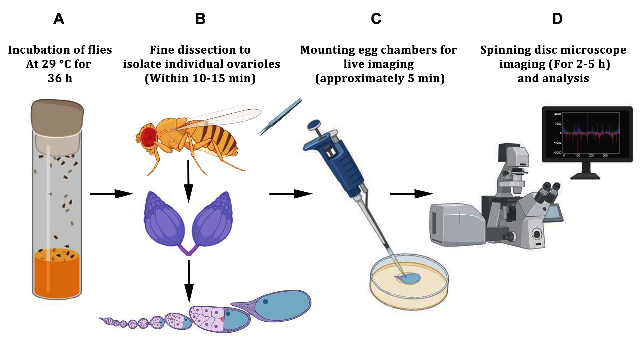
Schematic representation of the workflow for live-cell imaging of desired egg chambers. (A) Five to six females, along with 2–3 males, are incubated in a vial containing fly food supplemented with dry yeast. The flies are incubated at 29 °C to induce the development of egg chambers (termed as fly fattening). (B) The fattened female flies are dissected into live imaging media. The ovaries are taken out of the abdomen using a pair of forceps, followed by gently pulling out the individual egg chambers from the sheath of the ovarioles. (C) Using a 200 μL tip, the desired egg chambers, along with dissection media, are carefully aspirated and evenly distributed onto a poly-D-Lysine-coated coverslip in the imaging dish. (D) Imaging is carried out using a spinning disk confocal microscope. The images are analyzed using Fiji software.
Background
Membrane protrusions are specialized cellular structures that perform diverse functions, including environmental sensing, generation of traction forces during cell migration, and mediation of intercellular communication. Beyond their roles in normal development and cellular homeostasis, these structures are also implicated in disease progression [1]. In developing multicellular organisms, membrane extensions enable long-range communication between cells, which is crucial for coordinating complex morphogenetic processes.
Membrane protrusions exhibit substantial structural and functional diversity and are described by various terms, such as cytonemes, tunneling nanotubes (TNTs), membrane nanotubes, and microtubule-based nanotubes (MT-nanotubes) [2,3]. While these structures can connect distant cells, they differ in cytoskeletal composition and function. Cytonemes are predominantly actin-based extensions that facilitate the targeted delivery of signaling molecules to neighboring cells [4]. In contrast, nanotubes are generally microtubule-based and support a broader range of cellular activities, including the transport of vesicles, organelles, signaling molecules, and survival factors [5,6]. Long, narrow protrusions (typically less than 1.5 μm wide) that span several cell diameters are commonly classified as MT-nanotubes [7]. When these nanotubes form open connections between cells, they enable direct cytoplasmic exchange. While this connectivity can support normal physiological communication, it can also be exploited by pathogens or cancer cells to promote survival and disease progression.
Closed membrane nanotubes, on the other hand, often function in paracrine or juxtacrine signaling and play essential roles in tissue morphogenesis [8]. For example, in the Drosophila male germline, closed nanotubes mediate communication between germline stem cells and hub cells, maintaining stem cell identity [9]. Similarly, actin-based protrusions coordinate myoblast fusion during muscle development, and cytonemes facilitate long-range morphogen signaling during Drosophila wing and eye development [10,11]. Despite the diversity, the mechanisms underlying nanotube formation and function remain poorly understood. Drosophila micropyle development provides a useful model to study how thin membrane protrusions contribute to organ morphogenesis. The micropyle is a tubular structure at the anterior end of the eggshell that allows sperm entry during fertilization [12]. From stage 12 onward, a thin protrusion from the polar cells extends into the developing micropyle and generates an open channel in the eggshell that serves as an entry point for fertilizing sperm (Figure 1A–E) [13].
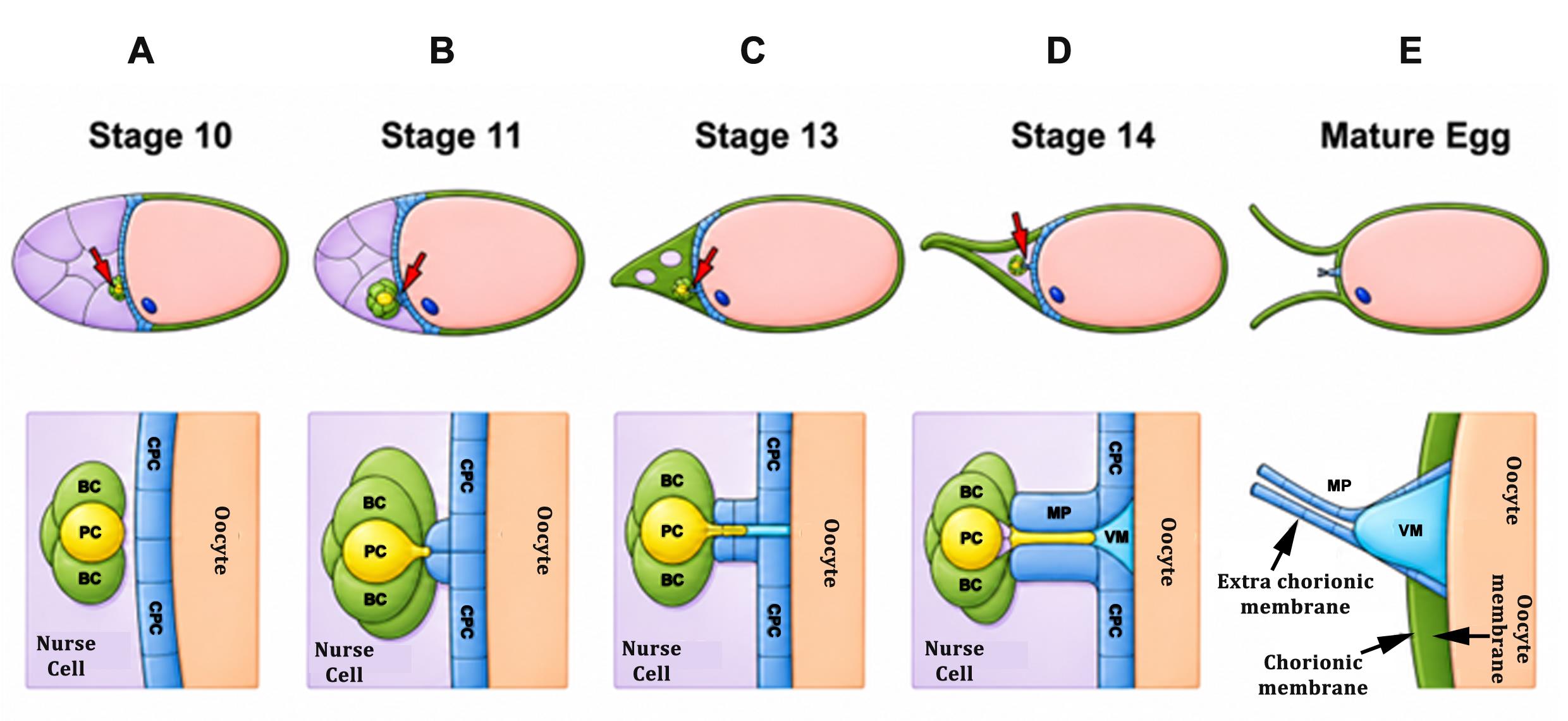
Figure 1. Schematic of stage-wise tubular morphogenesis of the micropyle at late oogenesis. (A) By stage 10, the border cell (BC) cluster has completed its migration and reaches the oocyte, while the centripetal follicle cells (CFCs) begin migrating inward from both the dorsal and ventral sides of the egg chamber. These CFCs move to enclose the anterior region of the oocyte, creating a partition between the nurse cells (NCs) and the oocyte. (B) At stage 11, CFC migration is completed, and they initiate the early steps of tubular morphogenesis of the micropyle. Concurrently, polar cells (PCs), located centrally within the BC cluster, begin to form a protrusion directed toward the oocyte surface, marking the tip of the developing micropyle. (C–E). From stage 13 onward, this protrusion elongates into a narrow, thin extension that pierces the forming tubular structure, contributing to the creation of an open channel that serves as the conduit for fertilizing sperm. In the schematic representation, NCs are depicted in pastel purple, the oocyte in pastel magenta, BCs in green, PCs in yellow, CFCs in blue, the vitelline membrane (VM) in sky blue, and the complete extra chorionic structure known as micropyle (MP). (Images were modified from Acharjee et al. [13].)
A major challenge in studying these tubular structures is that they are extremely thin, fragile, and dynamic. Fixed-tissue imaging provides useful structural information but captures only static snapshots, making it difficult to resolve protrusion formation, extension, remodeling, and interactions with surrounding cells. In addition, delicate membrane structures may be distorted or lost during fixation. Thus, live-cell imaging offers a key advantage by enabling direct visualization of protrusion dynamics in real time and revealing the cellular events that drive morphogenesis.
Here, we describe an optimized live-cell imaging protocol for visualizing the polar cell protrusion during micropyle morphogenesis in Drosophila egg chambers. The protocol includes methods for accurate staging and fine dissection of egg chambers, which are essential for isolating intact samples at the appropriate developmental window. We also optimized the ex vivo culture conditions to maintain egg chamber viability for extended imaging periods, allowing continuous observation of this dynamic event. In addition, imaging parameters were refined to minimize phototoxicity and sample heating during prolonged acquisition, preserve tissue health, and prevent imaging-induced artifacts. These optimizations improve sample stability and image quality, enabling reproducible acquisition of high-resolution datasets across the complete morphogenetic process. The protocol is also compatible with pharmacological treatments, providing a practical platform for functional perturbation experiments in isolated egg chambers. Overall, this method offers a robust and accessible approach for studying dynamic membrane protrusions in living tissue and, with minor modifications, may be adapted to investigate related developmental processes in other insect systems.
Materials and reagents
Biological materials
1. Drosophila stocks: Flies with the fluorescent reporter UAS mCD8::GFP (BL-5237), UAS GFP (BL-6874) were employed; upd-GAL4 (gifted by Dr. Harrison) was used for driving the overexpression of fluorescent reporter in the polar cells
Reagents
1. Non-absorbent cotton wool (Bengal Surgicals Limited)
2. Local sugar
3. Agar powder (SRL, catalog number: 19661)
4. Yeast (AB-MAURI)
5. Cornflour (Ganesh)
6. Malt (SRL, catalog number: 83358)
7. Propionic acid (Merck, catalog number: DH3D-731323)
8. Orthophosphoric acid (Merck, catalog number: CL9C690802)
9. Benzyl-benzoate (LOBA Chemie, catalog number: 0004700500)
10. Ethanol (Merck, catalog number: 1.00983.0511)
11. Phosphate buffered saline (PBS) (Sigma, catalog number: P3813)
12. Schneider's media (Life Technologies, catalog number: 21720-024)
13. Insulin, 10 mg/mL (Sigma, catalog number: I5550) dissolved in acidified water
14. Fetal bovine serum (FBS) (Gibco, catalog number: A5256801)
15. poly-D-Lysine (Sigma-Aldrich, catalog number: P7280)
16. Halocarbon oil 27 (Sigma-Aldrich, catalog number: H8773)
17. Pen-strep (Life Technologies, catalog number: 15140-122)
18. Fungizone (HyClone, catalog number: SV30078.01)
19. Sodium hydroxide pellets purified (Merck, catalog number: 1064980500)
20. Acetic acid glacial, 90%–100% (Merck, catalog number: 1.93402.0521)
Solutions
1. Live imaging Schneider’s medium cocktail (see Recipes)
2. Fly food media (see Recipes)
3. Acidified water (see Recipes)
Recipes
1. Live imaging Schneider’s medium cocktail (for 15 mL) [14]
| Component | Concentration | Composition (in 15 mL) |
|---|---|---|
| Schneider’s medium | - | 10.8 mL |
| FBS | 15% | 2.25 mL |
| Pen/strep | 0.01% | 1.5 μL |
| Fungizone | 0.001% | 0.15 μL |
| Insulin | 0.2 mg/mL | 300 μL (add fresh before use) |
2. Fly food media (for 1 L)
| Component | Composition (in 1 L) |
|---|---|
| Cornflour | 75 g |
| Sugar | 80 g |
| Dry yeast | 15 g |
| Malt extract (3%) | 30 g |
| Agar-agar | 10 g |
| Water | Up to 1 L |
| Propanoic acid | 5 mL |
| Orthophosphoric acid | 1 mL |
| Benzyl-benzoate | 5 mL (from 5% solution in EtOH) |
3. Acidified water
Add 1 μL of concentrated 37% HCl to 1 mL of water.
Laboratory supplies
1. Fly culture vials (Crystal make)
Equipment
1. Incubator at 25 and 29 °C for Drosophila stock maintenance and cross-incubation
2. Laminar flow hood (BIOAIR, model: s@feflow0.9)
3. Stereo microscope (Olympus, model: SZX16)
4. Epi fluorescence microscope (Olympus, models: IX81, IX83)
5. Confocal microscope (Nikon, model: AX, with NIS Elements software)
6. Spinning disk microscope (Olympus, model: IX83 spinning disk microscope)
7. Greiner Lumox culture dish hydrophilic (50 mm) (Sigma, catalog number: Z376744)
8. Paintbrush (1–5 size range) (Dayal Series-68 Taklon Round P)
9. Grooved slide (Samtech Instruments)
10. Dumont #5 forceps (Fine Science Tools, catalog number: 11251-20)
11. Micropipette with disposable tips (1,000 μL, 200 μL, 20 μL, 10 μL) (Gilson)
12. No. 1 coverslips (Fisher, catalog number: 12-542-B)
13. pH meter (BR Biochem)
Software and databases
1. ImageJ/Fiji (ImageJ 1.53f51)
2. Cell sense dimension (V 4.4)
3. NIS-elements (AR.20.00)
4. Microsoft Excel (Microsoft Office 365)
5. GraphPad Prism 9 and 6
Procedure
A. Preparation of coated coverslips
1. Place the coverslips in a 50 mL centrifuge tube and wash them overnight in a 1:1 acetic acid–ethanol solution to ensure thorough cleaning.
2. Following the wash, let the coverslips dry completely by incubating them at 37 °C for 2–3 h. Since egg chambers generally do not adhere well to glass surfaces, apply ~200 μL of a 100 μg/mL poly-D-lysine solution to each cleaned coverslip to ensure full coverage, thereby promoting attachment and maintaining stability during imaging.
3. Incubate the coated coverslips at 37 °C overnight to allow the coating to dry.
4. The following day, incubate the coated coverslips in a laminar flow hood under UV light for 15–20 min to sterilize them, after which they are ready for sample preparation.
Caution:
1. Ensure that coverslips are completely dry after the acetic acid/ethanol wash before adding poly-D-Lysine.
2. During incubation at 37 °C, maintain sterile conditions by placing the coverslip in a 35 mm dish and sealing it with parafilm to prevent yeast or other microbial contamination, which could interfere with live-imaging experiments.
B. Preparation of adult females for ovary dissection
1. Fly stocks were maintained, and genetic crosses were carried out, at 25 °C in the dark under normal humidity conditions. Flies of the genotype upd-GAL4; UAS-mCD8-GFP and upd-GAL4; UAS-GFP were used for live-imaging polar cell protrusion formation.
2. Transfer 5–6 non-virgin female flies aged 2–4 days of the desired genotype, along with 2–3 males of the same genotype, into a fresh food vial supplemented with a small amount of dry yeast. Incubate the flies at 29 °C for 36 h prior to dissection to enhance spatio-temporal GAL4 expression and promote oogenesis. Select the female flies with visually enlarged abdomens (fattened flies) for dissection.
Caution: Flies should not be older than 4 days, as this is critical for ensuring healthy females and normal oogenesis. Older flies may retain mature eggs, exhibit abnormal egg chamber morphology or impaired development, and may not fatten properly.
C. Dissection of ovaries to obtain ovarioles or individual egg chambers
1. Anesthetize 2–3 properly fattened adult females of the appropriate genotype using CO2.
2. Prepare a clean, grooved slide for collecting the dissected egg chambers.
3. Fill one well of a grooved slide with Schneider’s medium cocktail (approximately 200–300 μL) and place it under a dissecting microscope. Please note that insulin is added to the Schneider’s medium cocktail just before the dissection is initiated.
4. Using a pair of forceps, gently grasp a female fly and hold it under the medium with the wings facing upward (Figure 2B). With another pair of forceps, pinch a small portion of the abdominal cuticle and gently pull to expose the pair of white, opaque ovaries (Figure 2C, D). Repeat this step for each female and collect the ovaries in the Schneider’s medium cocktail.
5. With one pair of forceps, gently hold the posterior region of the ovary, where the older egg chambers are located. With the other pair, hold the anterior tip, which contains the germarium and early-stage egg chambers (Figure 2F).
6. Slowly pull the germarium or early-stage egg chambers using the forceps positioned at the anterior end. As the anterior region is gently pulled, the string of egg chambers will gradually emerge from the muscular sheath (Figure 2F). After removing the early-stage egg chambers, gently push from the posterior end using the forceps; the late-stage egg chambers will emerge from the sheath (Figure 2G). This procedure can be repeated several times for each ovary to obtain multiple ovarioles (Figure 2H). Figure 2I–K shows representative egg chambers at different stages of development.
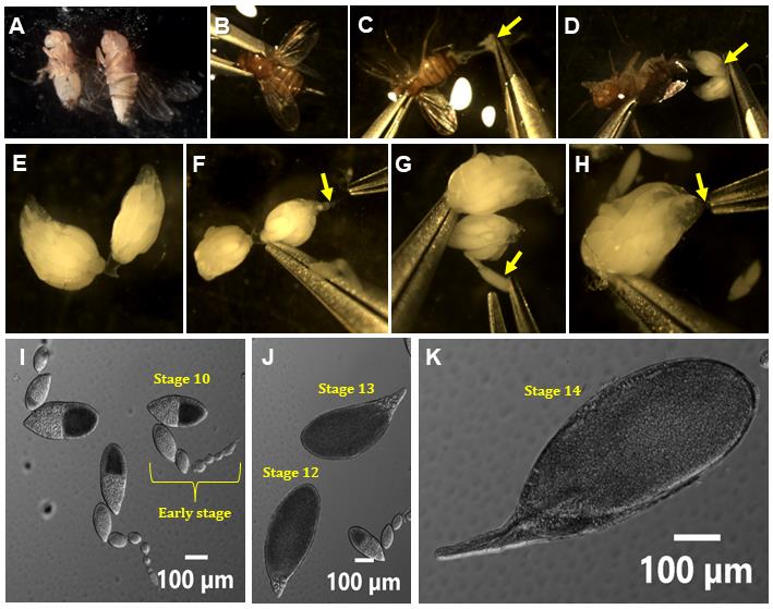
Figure 2. Detailed procedure for procuring egg chambers from Drosophila ovaries. (A) Adult Drosophila male (left) and female (right). The female can be distinguished from the male as it is typically bigger in size, with a pointed abdominal tip and the absence of a sex comb in the first leg pair. (B) To dissect a Drosophila, hold the thorax portion of the fly carefully with a pair of forceps so that the wings face upward. (C) While the fly fully submerges in the dissecting medium, use another pair of forceps to pinch off a small area of the abdomen (yellow arrow) to expose the oviduct. (D) By holding the oviduct (yellow arrow), gently extract the pair of white, transparent ovaries. (E) A pair of ovaries consists of approximately 18–20 ovarioles, and each ovariole contains a chain of interconnected developing egg chambers. The anterior tip of each ovariole contains the germarium and early-stage egg chambers, whereas the posterior tip is occupied by later developmental stages. (F) Hold the posterior region of the ovary firmly with one forceps; using another one, gently pull out the strings of egg chambers from the anterior side (yellow arrow). (G) As the early-stage egg chamber comes out initially, a gentle push from the posterior side gradually helps the late-stage egg chamber to emerge from the sheath, marked by a yellow arrow. (H) Repeat the same process with the other ovary to get more desired egg chambers. The yellow arrow indicates the anterior tip of the ovary. (I) String of an early-stage egg chamber containing the germanium at the tip and interconnected by stalk cells. (J) Late-stage egg chamber (stages 12 and 13). (K) Late-stage egg chamber (stage 14).
7. If early-stage egg chambers (germarium to stage 8) remain attached to stage 12–13 egg chambers (Figure 2J), carefully separate them without touching the egg chamber of interest. Hold the germarium with one pair of forceps and use the other pair to sever the connection between the germarium and stage 8 egg chambers. Ensure that only the non-target egg chambers are manipulated to minimize the risk of damaging the desired stage.
Caution:
1. From this step onward, all manipulations should be performed at room temperature (23–26 °C) unless otherwise specified.
2. During dissection, ensure that the abdominal muscles and fat bodies are carefully removed from the dissected ovaries.
3. Handle the ovaries gently from the posterior end to avoid damaging stage 12–13 egg chambers, as any damage can prevent proper polar cell protrusion formation.
4. Do not touch the dissected egg chambers with the sharp edge of the forceps. Even minimal or undetectable damage under the microscope can disrupt polar cell protrusion formation, even if overall egg chamber development appears unaffected. Obtaining only a few high-quality stage 12–13 egg chambers is sufficient for the experiment.
5. Avoid transferring large numbers of early-stage egg chambers onto the Lumox dish, as this may interfere with subsequent imaging.
6. Avoid heating the depression slide during dissection, as this could affect the viability of the egg chambers.
D. Mounting egg chambers
1. Prepare a Lumox dish for mounting the egg chambers. Break a 22 × 22 mm thin Fisherbrand coverslip into two halves. Place the two pieces approximately 1 cm apart on the Lumox membrane. Use a fine paintbrush to gently position the coverslip fragments on the membrane (Figure 3A, B) [15].
2. Using a plastic transfer pipette, transfer the dissected egg chambers along with ~45–50 μL of Schneider’s medium cocktail to the center of the dish, positioning them between the two coverslip fragments. These coverslip pieces act as spacers, preventing the stage 12–13 egg chambers from being crushed when the top coverslip is placed before imaging (Figure 3C, 3C–E).
3. Carefully place a 22 × 22 mm poly-D-Lysine-coated coverslip over the mounted egg chambers (Figure 3D).
4. Gently remove excess Schneider’s medium cocktail from the edges of the coverslip using a pipette tip or absorbent paper until the stage 12–13 egg chambers remain completely immobile when the Lumox dish is gently moved.
5. Seal the edges of the coverslip by applying a very thin layer of Halocarbon Oil 27 around the sides to minimize evaporation of the medium during imaging (Figure 3E).
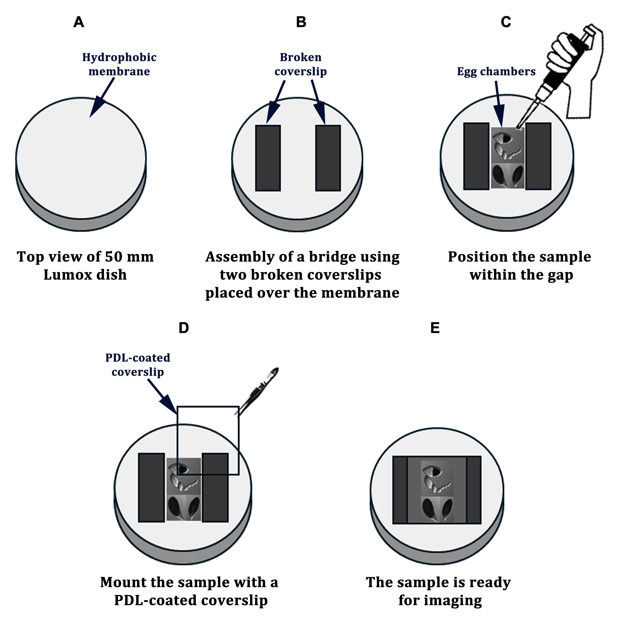
Figure 3. Schematic illustration of the culture chamber (top view). (A–E) The top view depicts the final configuration after sample mounting, ready for imaging. Coverslip bridges are indicated in dark gray and are placed directly on the membrane of the Lumox dish (B). Samples are positioned within the gap between the bridges (C). A PDL-coated coverslip is then gently placed over the sample (D). Finally, the preparation is mounted using halocarbon oil and is ready for imaging (E).
Caution:
1. Take care not to damage the Lumox membrane with the sharp edges of the broken coverslip fragments. Any damage to the membrane will make the dish unusable.
2. Avoid transferring debris or tissue fragments, as these can reduce image quality and interfere with imaging.
3. Ensure that the top coverslip remains properly supported by the coverslip spacers. If the coverslip slips between the spacers, it may crush the egg chambers.
4. Do not remove excessive amounts of medium, as insufficient medium can cause the egg chambers to become compressed or fail to develop properly.
5. Avoid using excess Halocarbon Oil 27, as too much oil can cause the coverslip to float, resulting in sample movement during imaging.
E. Time-lapse microscopy of living egg chambers
1. Place the Lumox dish on the microscope stage and identify an egg chamber at the desired developmental stage. Avoid egg chambers that display abnormal morphology, discontinuities in the outer follicle cell layer, or any visible defects. Additionally, select egg chambers located away from the germarium, as the germarium exhibits intrinsic pulsatile movements that can cause nearby egg chambers to drift during imaging.
2. Using a low-magnification objective (e.g., 4× objective on a spinning disk microscope), adjust the focus and determine the appropriate exposure settings. Define the overview region of interest and acquire the selected area. Time-lapse imaging was performed by acquiring z-stack sections at 1 μm intervals using a 40× objective on an Olympus IX83 spinning disk microscope. Capture images at 1-min intervals with 20% laser power, with an exposure time of 40 ms, and binning set to 2. Simultaneously capture differential interference contrast (DIC) images to visualize the overall morphology of the egg chambers.
3. Time-lapse imaging can also be performed using alternative imaging systems. A 40× objective lens on an Olympus IX81 epifluorescence microscope and 100× magnification on an inverted Ti2 Eclipse microscope (Nikon, Japan) equipped with a confocal module (Nikon AX) and NIS-Elements software can be used. Imaging was performed by acquiring z-stack sections at 2.5 μm intervals, and egg chambers were imaged every 1 min using sequential Galvano scanning to minimize channel crosstalk, with a pinhole setting of 2.5 A.U., along with DIC imaging. On average, each time-lapse movie lasts approximately 5 h, and care should be taken to ensure imaging does not exceed this duration, as viability of the sample would be affected.
4. During time-lapse acquisition, periodically refocus the sample, if necessary, as polar cells can move along the z-axis.
5. After completing the experiment, carefully remove the coverslip from the Lumox dish and wash away the Halocarbon oil using ethyl alcohol. The Lumox dish can be cleaned and reused multiple times if the membrane remains undamaged.
Caution: Ensure that the entire egg chamber is not drifting within the field of view. Throughout the imaging duration, the egg chamber should exhibit signs of normal development, including polar cell protrusion formation, micropyle development, dorsal appendage formation, and rearrangement of outer follicle cells.
Critical: Excessively high exposure or shorter imaging intervals may induce phototoxicity, impair polar cell protrusion formation, or disrupt normal egg chamber development. Therefore, both exposure time and time interval between frames should be optimized for each microscope and camera system. The parameters described here can serve as a starting reference for optimization.
Data analysis
1. Flies used for live-cell imaging of polar cell protrusion formation were of the genotype upd-GAL4; UAS-mCD8-GFP and upd-GAL4; UAS-GFP. Time-lapse microscopy was performed as described earlier, with frames acquired at 1-min intervals. All experiments were conducted under identical culture conditions to ensure consistency. On average, each time-lapse recording lasted approximately 3–5 h.
2. The acquired images were analyzed using ImageJ software. A spatial scale was assigned to each image before analysis. Because the images were captured at 40× magnification, the pixel measurements were converted to micrometers using reference calibration images.
3. Polar cell protrusion length was determined by identifying the extension beyond the existing polar cell membrane at the tapered end of the cell (Figure 4A, B). The protrusion region was traced using the Freehand Line selection tool in ImageJ, and the length was quantified using the Measure function.
4. As polar cells exhibit a cone-shaped morphology during late oogenesis, any extension greater than 0.2 μm beyond the cell surface was defined as a protrusion.
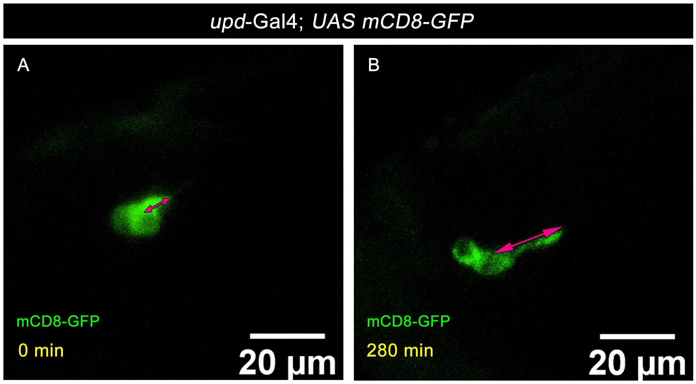
Figure 4. Polar cell protrusion formation is dynamic in nature. (A, B) Time-lapse snapshot of stage 12 egg chambers of the indicated genotype. GFP, green; magenta arrowheads mark polar cell protrusion length in different time points for quantification; number of egg chambers (n) = 10; biological replicates (N) ≥ 3.
5. The absolute protrusion length of polar cells was measured at 2-min intervals throughout the time-lapse sequence and plotted to visualize dynamic changes over time. The Δlength was calculated as the difference in protrusion length between two successive time points, providing a measure of protrusion dynamics.
Expected results
1. In late-stage 11 egg chambers, two stable and thin membrane protrusions were observed extending from the polar cells toward the oocyte membrane.
2. Around stage 12, centripetal follicle cells, together with the newly laminated border cell (BC) cluster, contribute to the formation of the micropylar structure, which emerges as a projection from the oocyte membrane. Concurrent with this process, a second, thicker protrusion originating from the polar cells extends toward the oocyte.
3. Time-lapse observations revealed that elongation of the polar cell protrusion was not continuous but occurred through intermittent cycles of extension and retraction.
4. By late stage 13, this thick protrusion appears to facilitate the formation of a narrow channel within the developing micropyle, which is essential for sperm entry during fertilization (Figure 5A–F, Video 1).
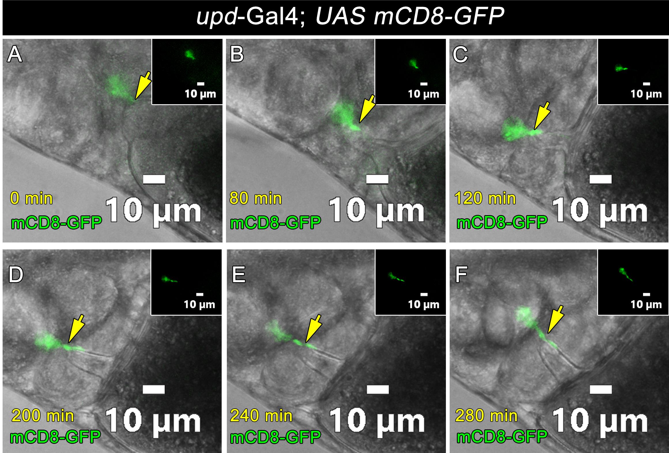
Figure 5. Polar cell protrusion formation. (A–F) Time-lapse snapshot of stage 12 egg chambers of the indicated genotype. GFP, green; yellow arrows mark polar cells, and white insets indicate the zoomed images of polar cell protrusion formation. Number of egg chambers (n) = 10; biological replicates (N) ≥ 3.

5. Quantitative measurements showed that the protrusion length extended up to a maximum of approximately 7 μm (data available at [13]). Although this length was largely maintained with minor fluctuations, the overall growth pattern was not linear.
6. Frame-by-frame analysis of protrusion length differences revealed both positive and negative values over time, indicating alternating phases of elongation and shortening. These observations suggest that protrusion formation is highly dynamic and pulsatile, characterized by repeated cycles of extension and retraction (data available in [13]).
Validation of protocol
The reliability and repeatability of this live-cell imaging protocol were confirmed through multiple independent experiments and a quantitative analysis of polar cell protrusion dynamics during Drosophila micropyle morphogenesis.
All live-imaging experiments were conducted under the same culture and imaging conditions, as outlined in the Data analysis section. Typically, 3–5 independent egg chambers are imaged per experiment, and the experiments are repeated with various biological replicates, which include different batches of flies and dissections. Only stage 12–13 egg chambers with intact morphology and normal development are included as internal quality controls. Egg chambers that show defects, such as a disrupted follicle cell layer or lack of normal morphogenetic features like dorsal appendage formation, are excluded from analysis.
Using this protocol, we consistently observed polar cell protrusion formation across replicates, indicating high reproducibility. Quantitative measurements showed that protrusion length reached up to approximately 7 μm, with dynamic changes over time. A time-resolved analysis, measured at 2-min intervals, revealed consistent cycles of extension and retraction. This indicates that the observed behavior is not random noise but a biologically controlled and measurable phenomenon. The use of consistent imaging intervals, regulated laser power, and specific protrusion measurement criteria (over 0.2 μm beyond the cell surface) ensures reliable data collection across experiments.
Controls for protocol validation include:
1. Developmental progression control: Only egg chambers showing normal oogenesis progression, such as outer follicle cell rearrangement, micropyle formation, and cytoplasmic dynamics, were analyzed.
2. Imaging condition control: Low laser power (20%) and optimized exposure time (40 ms) were employed to minimize phototoxicity, ensuring that protrusion dynamics were not caused by imaging artifacts.
3. Sample integrity control: Gentle dissection and mounting ensured that only undamaged egg chambers were analyzed, since mechanical damage is known to hinder protrusion formation.
Although detailed statistical tests are outlined in the Data analysis section, the consistency of protrusion dynamics across multiple independent samples provides strong evidence for repeatability.
This protocol allows for long-term live imaging (3–5 h) while keeping the tissue viable, which is vital for observing dynamic morphogenetic processes. The ability to reproducibly see protrusion formation, elongation, and remodeling across multiple samples further confirms the strength of the method.
This protocol, or portions of it, has been used and validated in the following research article(s):
• Acharjee et al. [13]. Polar cell membrane nanotubes containing microtubules and acidic vesicles make Drosophila eggs fertile. PLoS Biology (Figures 3 and 4, quantitative analysis of protrusion dynamics).
The published dataset linked to this study (DOI: https://doi.org/10.1371/journal.pbio.3003533) provides independent validation of the protocol, including time-lapse imaging, quantitative measurements, and dynamic analysis of protrusion behavior, all generated using the methods described here.
These results show that the protocol is reliable, repeatable, and suitable for quantitative live-cell imaging of dynamic membrane protrusions in Drosophila egg chambers.
General notes and troubleshooting
General notes
1. Multiple position imaging: When performing multi-position imaging, it is advisable to image 3–5 egg chambers per experiment. Selecting too many egg chambers may increase laser exposure and local heating, which can negatively affect sample viability.
2. Cleanliness of instruments: Forceps should be thoroughly cleaned and free from rust or surface damage. Depression slides must be cleaned with 70% ethanol and allowed to dry completely before use. Any residual ethanol on the slide may compromise egg chamber viability.
3. Media quality: The culture media should always be checked for any signs of contamination before use to ensure optimal sample health during imaging.
4. Insulin supplementation: Insulin should be freshly added to the culture media immediately prior to the experiment to maintain optimal physiological conditions.
5. Media pH: The pH of the medium is critical for maintaining egg chamber viability and should be carefully measured using a pH meter and adjusted to approximately pH 7.4 with 5 N NaOH before use.
Troubleshooting
| Step | Problem | Reasons | Solutions |
|---|---|---|---|
| D2 | Egg chamber moves under the coverslip after adding the halocarbon oil | Excess media on Lumox dish and halocarbon oil | Use a piece of tissue paper and place it gently at the edge of the coverslip to absorb excess media. Carefully pipette out the remaining halocarbon oil until the egg chambers remain stable and do not move when the Lumox dish is gently shaken. |
| E2 | No polar cell protrusion formation after a period of time | Phototoxicity; abnormal pH; excess compression | Try using a lower magnification objective and avoid imaging more than five positions simultaneously, as imaging too many positions may increase light exposure and reduce sample viability. Alternatively, reduce the intensity of the incident light by using a stronger neutral density filter, if possible, shortening the exposure time, using a faster shutter speed, or working with samples that have higher GFP expression levels. During spinning disk microscopy, laser power should be minimized whenever possible, and the pinhole size may be increased to approximately 2.5 A.U. to reduce phototoxicity during confocal. |
| E1 | Egg chambers move during the experiment | Excess medium, allowing the egg chambers to float; presence of early stages of egg chambers that heat the sample during imaging | Pipette out the excess medium and overlay with a reduced amount of halocarbon oil.During sample preparation on the Lumox dish, remove early-stage egg chambers. |
| E1–2 | Egg chambers do not show signs of normal development, like outer follicle cell rearrangement, oocyte growth, and cytoplasmic streaming or dynamic changes in gene expression | Problem with the Schneider's cocktail | Prepare everything fresh or change the FBS lot. |
Acknowledgments
Conceptualization, B.S., S.A., M.P.; Investigation, B.S., S.A., J.N.; Writing—Original Draft, S.A., B.S., M.P.; Writing—Review & Editing, S.A., B.S., M.P.; Funding acquisition, M.P.; Supervision, M.P.
We thank Dr. Harrison and Dr. Nina Sherwood for providing the crucial fly stock lines. We thank Bloomington Drosophila Stock Center (BDSC), the National Institute of Genetics (NIG, Japan), the Drosophila Genomics Resource Center (DGRC), Vienna Drosophila Resource Center (VDRC), and Developmental Studies Hybridoma Bank (DSHB) for providing reagents. We thank the IISER Kolkata imaging facility, particularly Ritabrata Ghosh, for capturing the images in the confocal LSM 710 and inverted Ti2 eclipse microscope (Nikon, Japan) with confocal module (Nikon AX model, with NIS elements software), and DBT Builder-IISER Kolkata imaging facility (BT/INF/22/SP45383/2022), Shreya Ghosh, for capturing the images in the Olympus spinning disk microscope.
This protocol was used in [13].
Competing interests
The authors declare no conflicts of interest.
References
- Gagliardi, P. A., Puliafito, A., di Blasio, L., Chianale, F., Somale, D., Seano, G., Bussolino, F. and Primo, L. (2015). Real-time monitoring of cell protrusion dynamics by impedance responses. Sci Rep. 5(1): 1–12. https://doi.org/10.1038/srep10206
- Tarakanov, A. O. and Goncharova, L. B. (2009). Cell-cell nanotubes: Tunneling through several types of synapses. Commun Integr Biol. 2(4): 359. https://doi.org/10.4161/cib.2.4.8289
- Yamashita, Y. M., Inaba, M. and Buszczak, M. (2018). Specialized Intercellular Communications via Cytonemes and Nanotubes. Annu Rev Cell Dev Biol. 34(1): 59–84. https://doi.org/10.1146/annurev-cellbio-100617-062932
- Ramírez-Weber, F. A. and Kornberg, T. B. (1999). Cytonemes: Cellular Processes that Project to the Principal Signaling Center in Drosophila Imaginal Discs. Cell. 97(5): 599–607. https://doi.org/10.1016/S0092-8674(00)80771-0
- Hall, E. T., Dillard, M. E., Cleverdon, E. R., Zhang, Y., Daly, C. A., Ansari, S. S., Wakefield, R., Stewart, D. P., Pruett-Miller, S. M., Lavado, A., et al. (2024). Cytoneme signaling provides essential contributions to mammalian tissue patterning. Cell. 187(2): 276–293.e23. https://doi.org/10.1016/j.cell.2023.12.003
- Rustom, A., Saffrich, R., Markovic, I., Walther, P. and Gerdes, H. H. (2004).Nanotubular Highways for Intercellular Organelle Transport. Science. 303(5660): 1007–1010.https://doi.org/10.1126/science.1093133
- Halász, H., Tárnai, V., Matkó, J., Nyitrai, M. and Szabó-Meleg, E. (2024).Cooperation of Various Cytoskeletal Components Orchestrates Intercellular Spread of Mitochondria between B-Lymphoma Cells through Tunnelling Nanotubes. Cells. 13(7): 607.https://doi.org/10.3390/cells13070607
- Driscoll, J., Gondaliya, P. and Patel, T. (2022). Tunneling Nanotube-Mediated Communication: A Mechanism of Intercellular Nucleic Acid Transfer. Int J Mol Sci. 23(10): 5487. https://doi.org/10.3390/ijms23105487
- Inaba, M., Buszczak, M. and Yamashita, Y. M. (2015). Nanotubes mediate niche–stem-cell signalling in the Drosophila testis. Nature. 523(7560): 329–332. https://doi.org/10.1038/nature14602
- Lee, D. M. and Chen, E. H.(2019).DrosophilaMyoblast Fusion: Invasion and Resistance for the Ultimate Union. Annu Rev Genet. 53(1): 67–91. https://doi.org/10.1146/annurev-genet-120116-024603
- Segal, D., Dhanyasi, N., Schejter, E. D. and Shilo, B. Z.(2016).Adhesion and Fusion of Muscle Cells Are Promoted by Filopodia. Dev Cell. 38(3): 291–304.https://doi.org/10.1016/j.devcel.2016.07.010
- Margaritis, L. H. (1984). Microtubules during formation of the micropylar canal in Drosophila melanogaster. Cell Biol Int Rep. 8(4): 317–321. https://doi.org/10.1016/0309-1651(84)90158-9
- Acharjee, S., Saha, B., Kumari, N., Nandi, J., Adhya, S., Karmakar, P. P. and Prasad, M. (2025). Polar cell membrane nanotubes containing microtubules and acidic vesicles render Drosophila eggs fertile. PLoS Biol. 23(12): e3003533. https://doi.org/10.1371/journal.pbio.3003533
- Prasad, M., Jang, A. C. C., Starz-Gaiano, M., Melani, M. and Montell, D. J. (2007). A protocol for culturing drosophila melanogaster stage 9 egg chambers for live imaging. Nat Protoc. 2(10): 2467–2473. https://doi.org/10.1038/nprot.2007.363
- Prasad, M., Wang, X., He, L., Cai, D. and Montell, D. J.(2015).Border Cell Migration: A Model System for Live Imaging and Genetic Analysis of Collective Cell Movement. Methods Mol Biol. 1328: 89–97. https://doi.org/10.1007/978-1-4939-2851-4_6
Article Information
Publication history
Received: Mar 25, 2026
Accepted: May 13, 2026
Available online: Jun 3, 2026
Published: Jul 5, 2026
Copyright
© 2026 The Author(s); This is an open access article under the CC BY-NC license (https://creativecommons.org/licenses/by-nc/4.0/).
How to cite
Saha, B., Acharjee, S., Nandi, J. and Prasad, M. (2026). Visualizing Membrane Nanotube Dynamics in Drosophila Oocyte Using Live-Cell Imaging. Bio-protocol 16(13): e5728. DOI: 10.21769/BioProtoc.5728.

 Download Citation in RIS Format
Category
Developmental Biology > Morphogenesis > Cell structure
Developmental Biology > Cell growth and fate > Oocyte
Cell Biology > Cell imaging > Live-cell imaging
Do you have any questions about this protocol?
Post your question to gather feedback from the community. We will also invite the authors of this article to respond.
 Post a Question


