- Protocols

- Articles and Issues
- For Authors
- About
- Become a Reviewer

Electroporation of Whole-Mount Postnatal Rodent Retinas for Advanced Functional Assays
Published: Vol 16, Iss 2, Jan 20, 2026 DOI: 10.21769/BioProtoc.5574 Views: 154
Reviewed by: Anonymous reviewer(s)
Original research article
The authors used this protocol in:

May 2022

Protocol Collections
Comprehensive collections of detailed, peer-reviewed protocols focusing on specific topics


Related protocols
Abstract
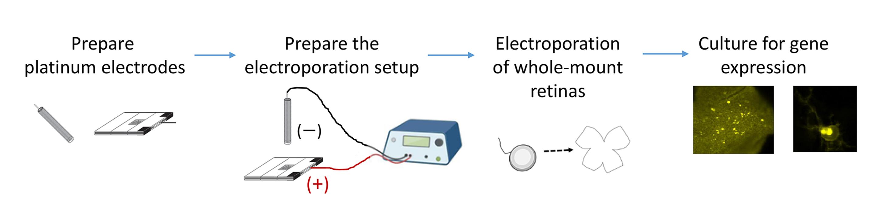
To study gene function in regulating rodent retinal waves during development, an efficient method for gene delivery into whole-mount retinas is required while preserving circuit functionality for physiological studies. We present an optimized electroporation protocol for developing rodent retinal explants. The procedure includes the fabrication of horizontally aligned platinum electrodes and the placement of retinal explants between them to generate a uniform electric field for high transfection efficiency. The entire process—dissection and electroporation—can be completed within 1–2 h. Successful transfection is verified by fluorescence microscopy, and physiological assays such as patch-clamp recordings and live imaging can be performed within 1–4 days following electroporation. This rapid and reliable protocol enables functional analysis for a specific gene in regulating retinal waves and can be adapted to other organotypic slice cultures.
Key features
• Incorporates horizontally aligned platinum electrodes and enables cell type–specific promoters to drive gene expression for physiological studies.
• Preserves retinal wave activity while markedly improving transfection efficiency in whole-mount postnatal rodent retinas.
• Requires only 1–2 h from retinal dissection to electroporation.
• Allows completion of functional experiments within four days after electroporation.
Keywords: ElectroporationGraphical overview
Background
A hallmark of developing neural circuits is recurrent, patterned spontaneous activity observed in many regions of the central nervous system, such as retinal waves in the developing visual system [1–4]. To investigate the molecular basis of this circuit activity, it is essential to combine gene delivery with physiological assays in the developing whole-mount retina. Among existing gene delivery methods—including transgenic approaches, viral infection, and biolistic delivery—electroporation provides a rapid, efficient, and flexible alternative. Unlike viral vectors, electroporation can express ectopic genes that may otherwise recombine with similar sequences, such as CFP and YFP, which interfere with FRET-based genetically encoded reporters [5]. These reporters, such as kinase activity sensors, have been successfully introduced into cells by microinjection [6], lipofection [7], or electroporation [8]. Both electroporation and biolistic transfection rely on physical means of macromolecule entry—via transient pore formation or membrane penetration, respectively—but electroporation is generally more cost-effective and efficient for postmitotic neurons. A key challenge in whole-mount retina electroporation is maintaining circuit functionality and preserving retinal waves.
Electroporation has been adapted for various experimental purposes, but each method has limitations. Commercial electroporation cuvettes with aluminum electrodes are widely used for dissociated neurons; however, they can generate toxic free radicals [9] and provide limited control over tissue orientation, critical for studies such as retinotopic mapping. Single-cell electroporation is effective for analyzing individual neurons but achieves limited transfection coverage, insufficient for manipulating network-level activity [10–12]. In vivo and in utero electroporation techniques have been applied to adult, neonatal, and embryonic rodents [13–18], yet they require extensive surgical skill and animal handling. Thus, a more accessible and scalable approach is needed to combine efficient gene delivery with preserved physiological properties in the developing whole-mount retina.
To address this need, we developed an optimized electroporation protocol for whole-mount rodent retinas that achieves high transfection efficiency while maintaining native retinal circuit function. The protocol described here is based on previous works [8,19–24]. We provide detailed descriptions of the construction and use of horizontally aligned platinum electrodes that generate a uniform electric field across the developing retina. Whole-mount retinal explants are positioned between the electrodes, and DNA solution is introduced into the gap to facilitate efficient and homogeneous gene transfer. These horizontally aligned platinum electrodes avoid the potential toxicity of aluminum electrodes and provide better control over tissue orientation. As a result, retinal waves remain intact following transfection, ensuring compatibility with physiological studies, including patch-clamp recordings and live imaging. This electroporation method has been successfully used to introduce the A-kinase activity reporter (AKAR) into retinal explants, enabling real-time monitoring of the temporal relationship between PKA activation and retinal waves—the characteristic spontaneous activity of developing retinas [8,19]. The protocol has also been adapted for cell type–specific gene expression, for example, using the mGluR2 promoter to target type II metabotropic glutamate receptor–expressing neurons [20–24], highlighting the versatility of the approach in dissecting the signaling pathways and cell-specific contributions that shape neural circuit development. This method requires only 1–2 h from retinal dissection to electroporation and preserves circuit integrity for up to several days in culture. Functional experiments, including patch-clamp recordings and live imaging, can be performed within four days after transfection. Researchers using this protocol are expected to be familiar with basic physiological techniques, which are described elsewhere [25–27]. Together, this optimized electroporation protocol enables short-term functional studies of gene regulation in neural circuit development. The same principles can be applied to other organotypic slice cultures, offering a versatile platform for investigating molecular and cellular mechanisms underlying neural circuit assembly.
Materials and reagents
Biological materials
1. Experimental animals: Postnatal Sprague–Dawley rats (P0-P2) or C57BL/6J mice (P0-P2)
Reagents
1. Hanks’ balanced salt solution (HBSS) (10×), calcium, magnesium, no phenol red (Gibco, catalog number: 14065056)
2. HEPES (Sigma, catalog number: H7523)
3. NaHCO3 (Sigma, catalog number: S-6014)
4. QIAGEN Plasmid Mega kit (Qiagen, catalog number: 12181, 12183, or 12281)
5. Tris (Sigma, catalog number: T6066; dissolve the powder in ddH2O to prepare a pH 7.4 solution)
6. Neurobasal-A medium (Gibco, catalog number: 10888022)
7. Glucose (Sigma, catalog number: G7528)
8. L-glutamine (Sigma, catalog number: G-6392)
9. B-27 supplement (50×), serum-free (Gibco, catalog number: 17504-044)
10. Sodium pyruvate (100 mM) (Gibco, catalog number: 11360070)
11. Insulin from bovine pancreas (Sigma, catalog number: I-1882-100MG)
12. Bovine serum albumin (BSA) (Cyrusbioscience, catalog number: 101-9048-46-8)
13. HCl (Sigma, catalog number: H1758)
14. Penicillin-Streptomycin (10,000 U/mL) (Gibco, catalog number: 15140-122)
15. Ciliary neurotrophic factor (CNTF) (100 μg/mL stock) (PeproTech, catalog number: 450-13)
16. Brain-derived neurotrophic factor (BDNF) (500 μg/mL stock) (PeproTech, catalog number: 450-02)
17. Forskolin (Sigma, catalog number: F-6886)
18. Dimethyl sulfoxide (DMSO) (sterile) (Sigma, catalog number: E-2438)
19. Ethanol (Sigma, catalog number: E-7023)
Solutions
1. Retinal dissection buffer (see Recipes)
2. DNA plasmid-containing solution (see Recipes)
3. Retinal serum-free culture medium–adult (SFCM-A) (see Recipes)
4. SFCM-A with forskolin (see Recipes)
Recipes
1. Retinal dissection buffer
| Reagent | Final concentration | Quantity or volume |
|---|---|---|
| HBSS (10×) | 1× | 100 mL |
| HEPES (1 M stock with pH 7.35–7.4) | 10 mM | 100 mL |
| NaHCO3 | 0.035% (w/v) | 0.35 g |
| ddH2O | n/a | n/a |
| Total | n/a | 1 L |
Critical: Mix all ingredients well and adjust the pH to 7.35. Filter-sterilize by vacuum filtration. Aliquot 50 mL per tube to avoid contamination. Store sterile at -20 °C.
2. DNA plasmid-containing solution
| Reagent | Final concentration | Quantity or volume |
|---|---|---|
| DNA plasmid stock (2 μg/μL) purified with the QIAGEN Plasmid Mega kit; dissolved in 10 mM Tris buffer, pH 7.4 | 0.2 μg/μL | 40 μL |
| Retinal dissection buffer | n/a | 360 μL |
| Total | n/a | 400 μL |
Critical: Store DNA plasmid stock at -20 °C. Aliquot the DNA plasmid-containing solution in 200 μL per Eppendorf to avoid the freeze-thaw-induced DNA fragmentation. For electroporation, freshly prepare sufficient DNA plasmid-containing solution for all explants using the following calculation: 400 μL × (the number of explants + 1). Use all DNA plasmid-containing solution; do not store leftovers, as DNA degrades readily in the dissection buffer.
3. Retinal serum-free culture medium–adult (SFCM-A)
| Reagent | Final concentration | Quantity or volume |
|---|---|---|
| Neurobasal-A medium | n/a | 47 mL |
| Glucose | 0.6% w/v | 0.3 g |
| L-glutamine (200 mM stock in ddH2O) | 2 mM | 500 μL |
| B-27 supplement (50×) | 1× | 1 mL |
| HEPES (1 M stock, pH 7.35–7.4) | 10 mM | 500 μL |
| Sodium pyruvate (100 mM) | 1 mM | 500 μL |
| Insulin (200× stock) | 2.5 μg/mL | 250 μL |
| Penicillin-streptomycin (10,000 U/mL) | 50 U/mL | 250 μL |
| CNTF (100 μg/mL stock) | 10 ng/mL | 5 μL |
| BDNF (500 μg/mL stock) | 50 ng/mL | 5 μL |
| Total | n/a | 50 mL |
Critical: Mix all well. Filter-sterilize by vacuum filtration. Prepare fresh. Store at -20 °C for 1 month or at 4 °C for ready use within 2 days.
Critical: For postnatal tissue culture, we must purchase Neurobasal-A (“A” stands for adult) from Gibco (catalog numbers 10888 with phenol red and 12349 without phenol red), which has an optimal osmolarity for postnatal and adult neurons. In contrast, Neurobasal from Gibco (catalog numbers 21103 with phenol red and 12348 without phenol red) has a relatively low osmolarity, which is suitable for embryonic neural tissue.
Critical: The recipe for 200× insulin stock is shown below; it contains 0.5 mg/mL insulin in 3 mM HCl and 0.1% BSA (pH 2.5). In the presence of 3 mM HCl, the pH is approximately 2.5. 0.1% BSA is required to stabilize insulin. Filter-sterilize, aliquot, and store at -20 °C.
| Reagent | Final concentration | Quantity or volume |
|---|---|---|
| Insulin | 0.5 mg/mL | 10 mg |
| BSA | 0.1% w/v | 20 mg |
| HCl (6 N) | 3 mM | 10 μL |
| ddH2O | n/a | bring the final volume to 20 mL |
4. SFCM-A with forskolin
| Reagent | Final concentration | Quantity or volume |
|---|---|---|
| Forskolin (30 mM stock) | 6 μM | 5 μL |
| SFCM-A | n/a | 25 mL |
Critical: Prepare fresh in the sterile hood. Store at -20 °C for 1 month or at 4 °C for ready use within 2 days. Aliquot the stocks in 20 μL per Eppendorf to reduce the freeze-thaw cycles to four times. Keep sterile at -20 °C.
Laboratory supplies
1. Platinum foil, 25 × 25 mm, 99.99% (Aldrich, catalog number: 349364–350 mg)
2. Ball-point pen (Tempo, catalog number G-102; also compatible with transparent ball-point pens with an outer barrel diameter of ~1 cm, an inner diameter >0.6 cm, and a body length >11.5 cm)
3. Electric wires, multi-core tinned copper, O.D. 1 mm with insulation, in red and black for the positive and negative electrodes, respectively (TopTech Wire and Cable, catalog number: 1007#24)
4. Electrical insulation tape (3M, catalog number: B40070579)
5. Epoxy glue (AB glue) (Success, catalog number: 1632), aluminum foil (Kirkland Signature, catalog number: RK611), and toothpicks (Diamond SKU, catalog number: 535-376-821)
6. Microscope slides, 8 slides (size “1 × 3”; thickness 1–1.2 mm) (Paul Marienfeld, catalog number: 1000412)
7. Soldering iron (Taiyo Electric Ind. Co., Ltd., catalog number: TQ-95)
8. Soldering tin (Shenmao Technology Inc., catalog number: PF606-R): lead-free SAC alloy (Sn 96.5%, Ag 3.0%, Cu 0.5%) with a rosin-based, non-acid “no-clean” flux; the recommended working temperature is typically 280–350 °C
9. BNC cable (Cal Test Electronics, catalog number: CT4452-100): one end features two banana plugs for connection to the electroporator, and the other end has a connector for attaching to the wires from the positive and negative electrodes
10. Stainless steel plate (e.g., a divider from an office cabinet) (UB office furniture, catalog number: UB4-30P)
11. Circular bubble level (Dogger, catalog number: D99C-09003)
12. Petri dish, 3.5 cm (Corning, catalog number: 430165)
13. Kimwipes (Kimtech, catalog number: 34155)
14. Razor blade (GEM, catalog number: 62-0165)
15. Mini-dissecting scissors (World Precision Instruments, catalog number: 503246)
16. Filter paper, No. 1 (Whatman, catalog number: 1001090)
17. Scalpel handle, No. 3 (World Precision Instruments, catalog number: 500236)
18. Scalpel blades, No. 10 (World Precision Instruments, catalog number: 500239)
19. Scalpel blades, No. 11 (World Precision Instruments, catalog number: 500240)
20. Vannas scissors (World Precision Instruments, catalog number: 500086)
21. Petri dish, 10 cm (Corning, catalog number: 430167)
22. Paintbrush (Samyick, catalog number: No. 0 or No. 1) to handle and dissociate the retinas
23. Forceps, Tweezers Dumont No. 5 (World Precision Instruments, catalog number: 14095)
24. Glass droppers (Volac, catalog number: D812), fire-polished tips
25. Black nitrocellulose filter paper, 0.45 μm (Millipore, catalog number: HABP02500)
26. 24-well cell culture plate (Corning, catalog number: 3524)
27. Vacuum filtration devices (Nalgene 90-mm filter units for 500 mL, catalog number: 8-0000-230301)
28. Syringe filters (Pall Corp., catalog number: PN4612)
Equipment
1. Square-wave pulse electroporator (Harvard apparatus, catalog number: BTX ECM830)
2. Micromanipulator (Marzhauser, catalog number: MM33)
3. Magnetic stand (Marzhauser, catalog number: M-10)
4. Clean bench
5. Ice box
6. Dissection microscope (Leica, catalog number: EZ4D)
7. Cell culture hood
8. Humidified CO2 incubator, 5% CO2, 35 °C (Sanyo, catalog number: MCO-5AC)
Procedure
A. Preparation of platinum electrodes (see Figure 1)
To prepare the electrodes for electroporation of retinal explants, create two separate devices: one for the positive electrode and one for the negative electrode.
Caution: Wear gloves to avoid direct contact with epoxy glue. Squeeze A and B glues separately onto different regions of the aluminum foil. Use a toothpick to mix the A and B glues. For best results, apply the mixture of the AB glues to seal the electrodes 1–2 min following mixing.
1. The positive electrode is composed of platinum foil on top of eight microscope slides (Figure 1A–D).
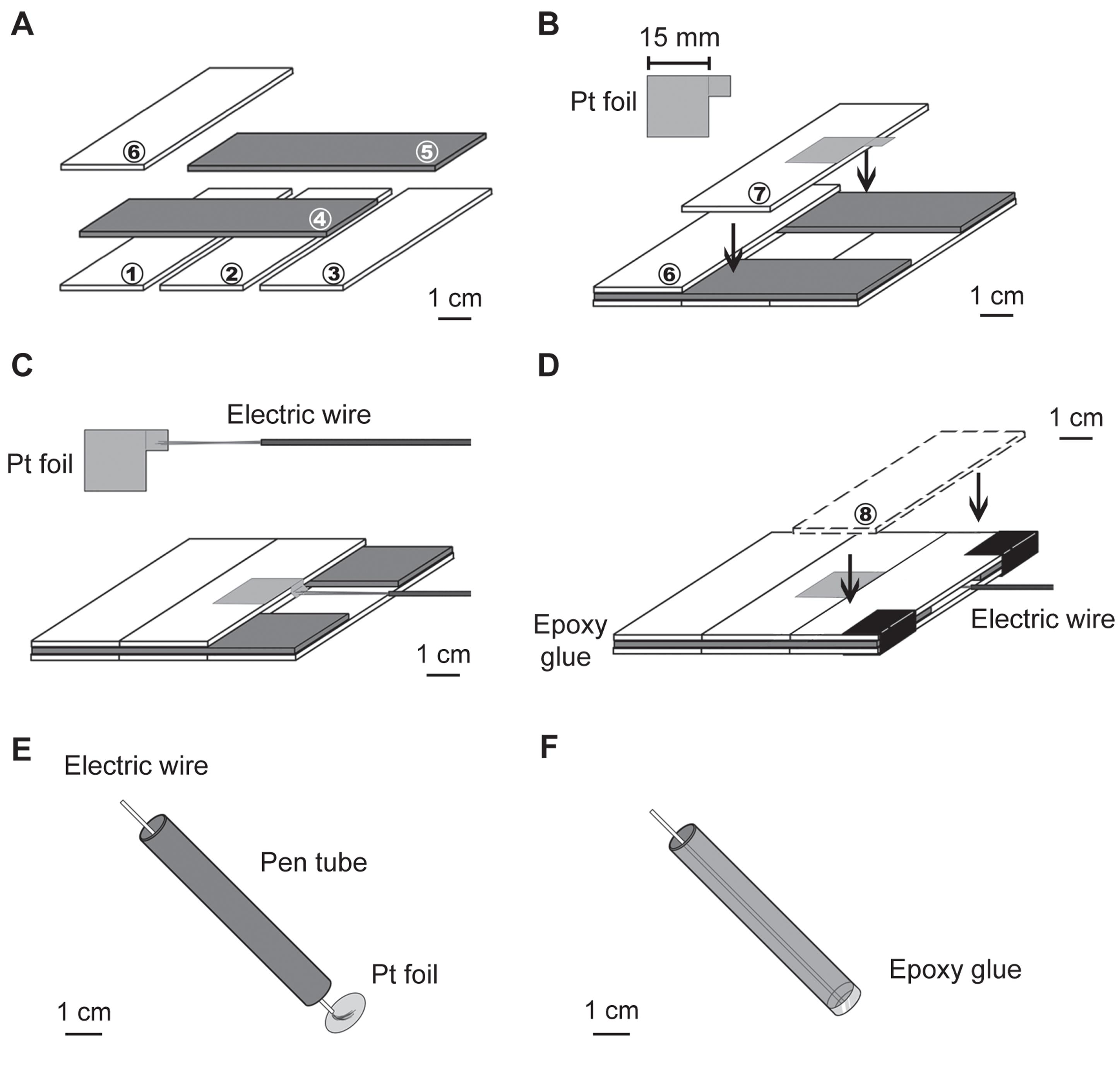
Figure 1. Preparation of platinum electrodes for electroporation with a horizontal configuration. (A) The arrangement of the base six slides. Dark gray slides represent the second layer. The numbers in the circles correspond to the slide numbers mentioned in the text. (B) The platinum (Pt) foil is aligned to one side of the seventh slide, leaving an overhanging square. (C) The wire is soldered to the edge of the overhanging platinum square. (D) The last slide is glued to the base. (E, F) Arrangement for making the negative electrode (modified from [21]).
a. Combine six slides (first to sixth) using epoxy glue into three layers to form the base slides (Figure 1A). The orientation of the two slides in the second layer is different from that of all the others.
b. Cut a 15 × 15 mm square piece of platinum foil with an overhanging 5 × 5 mm square for wire connection. Use epoxy glue to attach the platinum piece to the middle part of the seventh slide, leaving the overhanging square outside the slide for soldering to the electric wire (Figure 1B).
Critical: The platinum foil is easily cut by scissors. Before cutting, use a marker pen to draw the square with an overhang to make the electrode. The size of the platinum piece is determined by (cannot be less than) the size of the retinal explants and the diameter of the negative electrode. A larger platinum square conducts electroporation more easily, but a greater volume of DNA solution is required for transfection. Each transfection requires at least 380 μL of DNA solution (0.2 μg/μL) for this size of electrodes (final 1 × 1 cm square). A lower DNA solution concentration (e.g., 0.1 μg/μL) may lead to reduced transfection efficiency, whereas a higher concentration (e.g., 0.3 μg/μL) does not significantly improve efficiency. We recommend 380–400 μL of DNA solution (concentration: 0.2–0.3 μg/μL) for this size of electrodes. Increasing the incubation time with the DNA plasmid-containing solution can significantly improve transfection efficiency (see step D1).
Critical: The size of the overhanging square (5 × 5 mm) should be at least three times larger than the thickness of the slide, so that the electric wire can be embedded in the space between the first and the third layers of slides (Figure 1C).
Critical: The conductivity of the electrode will decrease if epoxy glue stains the main platinum square. Use 75% ethanol (or other organic solvents, e.g., ether or acetone) to clean the platinum piece after gluing.
c. Expose the red-colored electric wire by removing its surrounding insulating sleeve. Solder the multi-core wire to the overhanging square of the platinum piece on the seventh slide (Figure 1C). Attach the seventh slide to the base slides using epoxy glue. Stabilize the wire by gluing it to the first layer of the base slides.
Critical: The size of the soldering tin should be smaller than the thickness of the slides; otherwise, the soldering tin will become an obstacle for attaching the eighth slide to the base. Since positive electrode malfunction typically occurs at the connection point of the soldering wires, it is recommended to test the positive electrode conductivity before gluing the eighth slide.
d. Glue the eighth slide (Figure 1D). To avoid the solution leaking into the space between the first and third layers of slides, fill the seams between all slides with epoxy glue, e.g., the seams at the connection of the sixth to eighth slides and the side-view seams of the first and third layers of slides.
e. Use epoxy glue to make a well for containing the DNA solution.
Critical: To make a well for containing the DNA solution, first mix equal parts of epoxy glue (Part A and Part B) thoroughly with a toothpick. Next, apply the epoxy around the border of the positive electrode surface to form the walls of the well, leaving the base clean so the DNA solution can contact the platinum. Smooth and shape the walls to be vertical and uniform, filling any gaps to make the well leakproof. Allow the epoxy to cure according to the manufacturer’s instructions, typically for 1–2 h for initial setting and 24 h for full strength. After curing, test the well by adding a small volume of water to ensure it holds liquid without leaking before adding the DNA solution.
2. The negative electrode is composed of a platinum foil attached and sealed to one opening of a tube, inside which a black-colored wire is connected to the platinum foil by soldering. The tube can be any object with a thick wall and a flat cross-section, such as a ball-point pen tube, allowing the platinum piece to attach tightly.
a. Penetrate the multi-core wire through the hollow tube.
b. Cut a round platinum piece with a diameter larger than that (~1 cm) of the tube.
c. Solder the wire onto the center of the round platinum piece (Figure 1E).
d. Use epoxy glue to attach the platinum piece to the tube and ensure the sealing is waterproof (Figure 1F).
B. Preparation of the electroporation setup (see Figure 2)
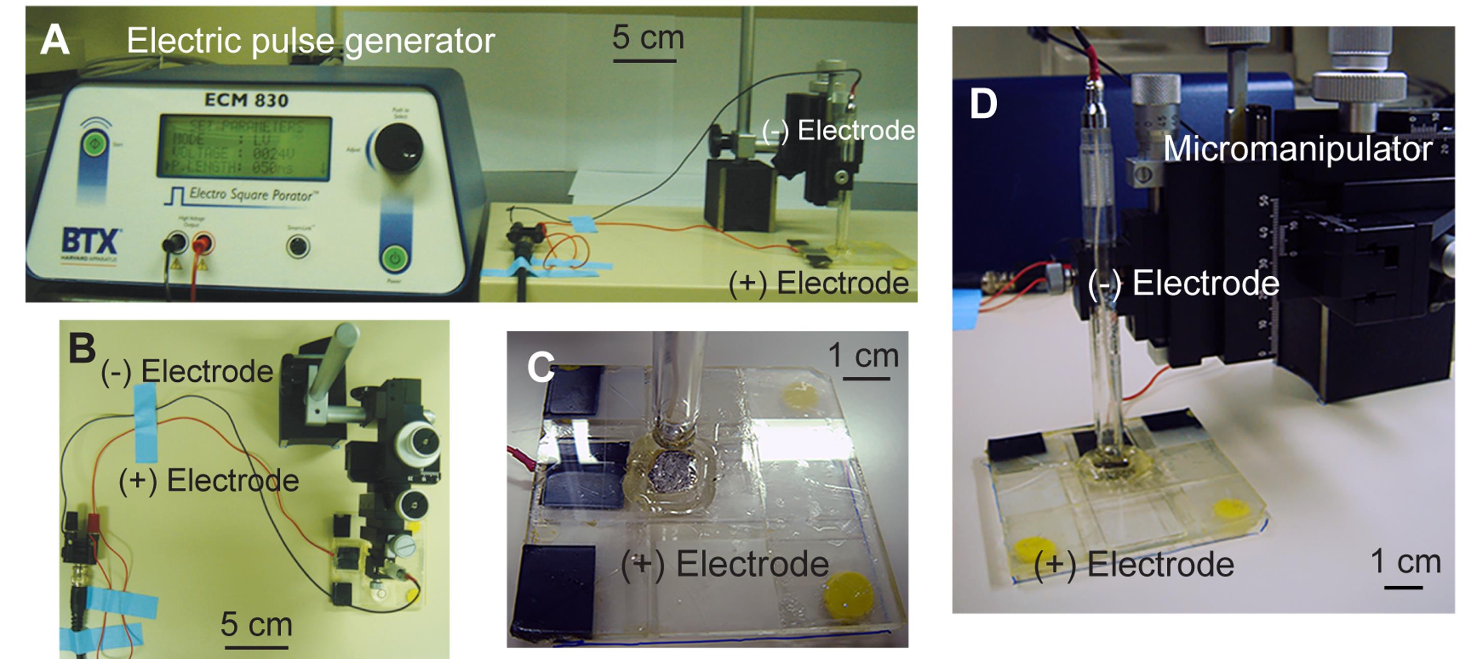
Figure 2. Electroporation setup. (A) Overview of the entire electroporation setup. (B) Connection of the positive (+) and negative (-) electrodes. The horizontal level is measured using a circular bubble level placed on the base of the positive electrode. (C) Positive electrode. (D) Measurement of the horizontal gap between electrodes using the micromanipulator (modified from [21]).
1. Establish the micromanipulator and the magnetic stand on the stainless-steel plate. Hold the negative electrode with the micromanipulator, allowing for three-dimensional fine adjustment.
2. Put the positive electrode in the fixed position on the stainless-steel plate to ensure a constant horizontal level.
Critical: The horizontal level of the positive electrode can be adjusted by attaching molding clay to the corners at the bottom of the slide base. Use the circular bubble level to measure the horizontal level.
3. Attach the electric wires to a connector with a BNC cable according to their respective colors. Connect the banana plugs at one end of the BNC cable to the electroporator (Figure 2A, B).
4. Before conducting electroporation, lower the negative electrode to touch the positive electrode and write down the z-position on the micromanipulator as the original point. Lift the negative electrode from its original position to the level used for the distance between the positive and negative electrodes during electroporation, e.g., 4 mm (Figure 2C, D).
Critical: When measuring the original point, it is essential to lower the negative electrode to gently touch the positive electrode; otherwise, the negative electrode may be slightly pushed up, making the original point inaccurate.
Critical: All equipment for electroporation must be sterilized with tissue paper containing 75% ethanol.
C. Preparation of retinal explant culture
1. Use a No. 11 scalpel blade and a clean No. 1 filter paper as the cutting board. Cut a nitrocellulose filter paper into six pie-shaped pieces and then trim them into six pentagons. The pointed end of each pentagon can serve as an orientation marker for the retinal explants. For subsequent patch-clamp experiments, cut a 1 × 1 mm square hole in the center of each pentagon-shaped filter paper to allow light transmission for visualizing the patch pipette and target neurons. Sterilize the filter papers (dark side facing up) under UV light for 30 min before use.
Critical: Store the filter papers in a dust-free environment. Wear dry gloves when handling nitrocellulose filter papers, as sweat or moisture can interfere with retinal attachment.
2. Anesthetize rat or mouse pups (P0–P2) on ice (typically 3–4 min for rat pups and 2–3 min for mouse pups). Decapitate the pups on a towel using a razor blade. Cut the eyelids with a No. 10 scalpel blade and enucleate the eyes using fine dissecting scissors.
Critical: All tools for surgery and culture must be sterilized using an autoclave, 75% ethanol, or UV.
3. Under a dissection microscope, place an eyeball on clean No. 1 filter paper and make a single cut between the iris and the retina using a No. 11 scalpel blade (Figure 3A). Transfer the eyeball to a 10-cm Petri dish containing retinal dissection buffer. Use Vannas scissors to cut around the iris (Figure 3B). With two No. 5 forceps, gently unfold the eyecup to expose the retina without severing the optic nerve (Figure 3C). Using No. 5 forceps and a paintbrush, carefully detach the blood vessels connected to the lens. Then, using two No. 5 forceps, grasp and stretch the optic nerve and blood vessels covering the retinal ganglion cell (RGC) layer to isolate the retina (Figure 3C, D). Cut each retina into halves or thirds.
4. Use a paintbrush and fine-tipped glass droppers to flip the retinal pieces (Figure 3E) so that the RGC layer faces the microscope slide (Figure 3F).
5. Lift the microscope slide with the retinal pieces from the buffer. Using forceps, attach the nitrocellulose filter papers onto the slide over the retinal pieces (Figure 3G). Add a few drops of retinal dissection buffer to rinse the filter paper (Figure 3H). Gently wick away the residual buffer with Kimwipes and remove the filter from the slide (Figure 3I).
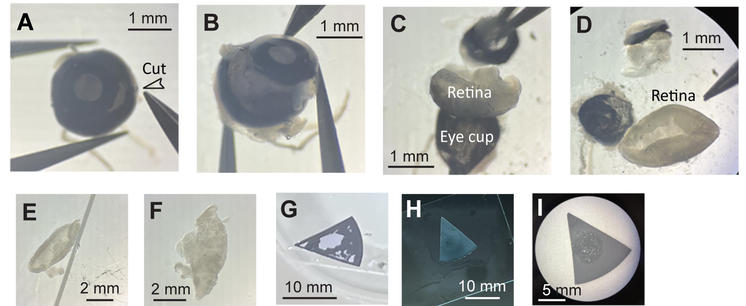
Figure 3. Dissection of whole-mount retinas for electroporation. (A) Make a single cut between the iris and the retina. (B) Cut around the iris. (C–D) Gently unfold the eyecup to expose the retina. Grasp and stretch the optic nerve and blood vessels covering the retinal ganglion cell (RGC) layer to isolate the retina. (E) The curvature bends the RGC layer inward; flip the retinal piece. (F) The RGC layer faces the microscope slide. (G) Attach the nitrocellulose filter paper onto the slide over the retinal piece. (H) Add a few drops of retinal dissection buffer to rinse the filter paper. (I) Overview of a whole-mount retinal piece after gently wicking away the residual buffer and removing the filter from the slide.
Critical: Ensure the dark side of the filter paper faces the microscope slide. This orientation positions the RGC layer upward against the dark background of the filter paper. Submerge each filter paper with its attached retina in a well containing 0.5 mL of SFCM-A with forskolin, and keep the retinal explant cultures in a CO2 incubator.
See troubleshooting: Discard any filter paper that becomes wet before attachment, as retinal pieces easily detach from pre-wetted filter paper during culture.
D. Electroporation of retinal explants
1. In a sterile culture hood, take the retinal explants out of the medium (SFCM-A with forskolin). Gently blot excess medium with sterile tissue paper. Incubate retinal explants in the DNA-containing solution for at least 10 min in the culture hood.
Critical: Freshly prepare sufficient DNA-containing solution for all explants. Incubate all explants together in a 3.5-cm dish containing this solution for at least 10 min. A longer incubation time (e.g., 30 min) yields better transfection efficiency.
Critical: The conductivity (σ) of this solution is calculated by summing the contributions of all ions—multiplying each ion’s molar concentration by its limiting molar conductivity—and converting to S/m, yielding approximately 1.75 S/m at 25 °C for this DNA-containing solution. Reducing the fraction of retina dissection buffer, which has a conductivity of 1.93 S/m, will lower the overall conductivity and reduce transfection efficiency.
2. Set up the electroporation apparatus as shown in Figure 2, ensuring a 4-mm gap between the negative and positive electrodes to maintain a constant electric field.
3. Using forceps, gently lift the filter paper with the retinal explant (the RGC layer facing up) and place it flat inside the well on top of the positive electrode (Figure 4A). The retinal explant should sit entirely within the well.
4. Add 400 μL of DNA-containing solution to cover the retinal explant and fill the well (Figure 4B).
Critical: The DNA-containing solution must connect both electrodes. To achieve this, lower the negative electrode into the well, then raise it back to the 4-mm position. This forms a continuous column of solution between the electrodes.
5. Confirm that the retinal explant is placed between the negative and positive electrodes, fully surrounded by the DNA solution (Figure 4C).
6. Set the BTX ECM830 electroporator parameters as follows:
Mode: LV (low voltage)
Voltage: 30 V
Pulse length: 50 ms
Number of pulses: 2
Pulse interval: 1 s
7. Press Start to perform electroporation.
Critical: Record the actual voltage applied after electroporation. The delivered voltage may differ slightly from the set value (e.g., a 30 V setting may produce an actual pulse of 27 V). For instance, 30 V across a 4-mm gap yields an electric field of 7.5 V/mm, whereas 27 V produces 6.75 V/mm. We recommend maintaining the field strength (E) below 7.5 V/mm (optimal range: 6.5–6.75 V/mm).
Critical: When the field strength (E) is 7.5 V/mm and the conductivity (σ) of the DNA solution is 1.75 S/m at 25 °C:
Current density: J = σ, E = 1.75 S/m × 7,500 V/m = 13,125 A/m2.
Current through the electrodes (~1 × 1 cm square; area = 1.0 × 10⁻⁴ m2): I = J, A = 13,125 × 1.0 × 10-4 = 1.3125 A.
For 400 μL of solution connecting the electrodes (V = 400 μL = 4.0 × 10⁻⁷ m3):
Instantaneous power dissipated in the 400 μL solution: P = p⋅V, where p = σ·E2 is the volumetric power density.
p = 1.75 × (7,500)2 = 98,437,500 W/m3, so P = 98,437,500 W/m3 × 4.0 × 10-7 m3 = 39.375 W ≈ 39.4 W.
Energy per 50-ms pulse: U = P·t = 39.375 W × 0.05 s = 1.96875 J ≈ 1.97 J per pulse.
Instantaneous temperature rise (assuming no heat loss during the pulse): ΔT = (p·t)/(ρ·cp), where ρ = 1,000 kg/m3 and cp = 4184 J/(kg·K).
ΔT = (98,437,500 W/m3 × 0.05 s)/(1,000 kg/m3 × 4184 J/(kg·K)) ≈ 1.1766 K ≈ 1.18 °C per pulse.
Dielectric permittivity (ϵ) of the solution characterizes its ability to store charge in an electric field:
ϵ = ϵr⋅ϵ0 = 78.5 × 8.854 × 10−12 = 6.95 × 10⁻¹⁰ F/m, where ϵr is the relative permittivity of the medium (~78.5 for water at 25 °C) and ϵ0 is the vacuum permittivity (~8.854 × 10⁻¹² F/m).
Charge-relaxation time: τ = ϵ/σ = 6.95 × 10⁻¹⁰/1.75 = 3.97 × 10⁻¹⁰ s ≈ 0.40 ns.
Because the pulse length (50 ms) is many orders of magnitude longer than τ (~0.40 ns), conduction current dominates and capacitive effects are negligible for this pulse width (i.e., charges relax very fast). Therefore, dielectric (capacitive) effects are negligible for 50-ms pulses in this setup.
8. Immediately after electroporation, transfer the explant back into SFCM-A with forskolin in the culture hood and return it to the CO2 incubator.
9. Verify the presence of bubbles on the platinum electrode surface as an indication of successful electroporation (Figure 4D).
Critical: For consecutive electroporations, reset the parameters each time. Clean the well and electrodes with 75% ethanol between samples. Avoid reusing the DNA-containing solution, as this significantly reduces cell viability.
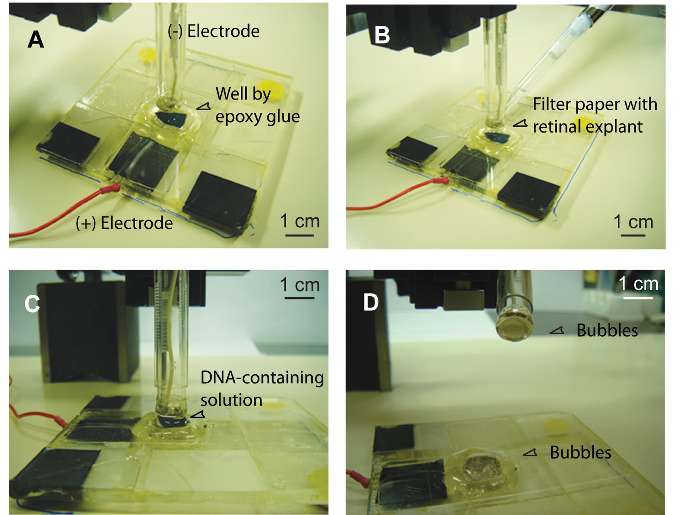
Figure 4. Procedure for electroporation. (A) A filter paper with the retinal explant attached is placed in the well on top of the positive electrode. (B) The DNA-containing solution is added to the well. (C) The retinal explant is covered by the DNA-containing solution and then subjected to electric pulses. (D) Bubbles form on the surface of both electrodes after electroporation.
E. Culture for gene expression
1. Transfer each electroporated retinal explant into a fresh well containing 0.5 mL of new SFCM-A with forskolin daily.
2. Before performing patch-clamp or live imaging experiments, incubate the explant in fresh SFCM-A without forskolin for 1–2 h. Successful expression is verified by fluorescence microscopy (Figure 5).
See troubleshooting: Although forskolin supports neuronal survival, axon outgrowth [28], and sodium current maintenance, it also increases the frequency and amplitude of retinal waves [29]. To preserve experimental flexibility in manipulating retinal waves, remove forskolin prior to functional studies.
Validation of protocol
This protocol (or parts of it) has been used and validated in the following research articles:
Chiang et al. [21]. Synaptotagmin I regulates patterned spontaneous activity in the developing rat retina via calcium binding to the C2AB domains. PLoS One (Figures 3–6 and Tables 1–2).
Huang et al. [22]. Adenosine A2A receptor up-regulates retinal wave frequency via starburst amacrine cells in the developing rat retina. PLoS One (Figures 2–5, Figures S1–S3, and Table S1).
Hsiao et al. [23]. Presynaptic SNAP-25 regulates retinal waves and retinogeniculate projection via phosphorylation. Proc Natl Acad Sci USA (Figures 1–4 and Figures S1–S4).
Chen et al. [24]. Phosphorylation of cysteine string protein-alpha up-regulates the frequency of cholinergic waves via starburst amacrine cells. Visual Neurosci (Figures 2–4).
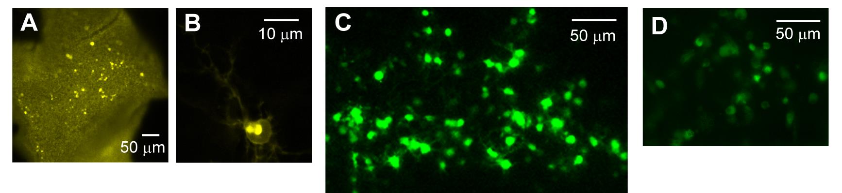
Figure 5. Expression of genes of interest after electroporation. (A–C) Gene expression in the retinal ganglion cell (RGC) layer. (A–B) Expression of the vesicle marker VAMP2-pHVenus [28] in the RGC layer. (A) Numerous transfected neurons were observed within the central hole of the filter paper. (B) VAMP2-pHVenus fluorescence was localized to the cell surface and putative Golgi-like structures. (C) Expression of the PKA-activity reporter AKAR [29] in the RGC layer. (D) Electroporation on the reverse (i.e., ventricular zone) side of the retina with EGFP revealed fluorescent neuroblasts. All expression patterns were obtained from rat retinal explants dissected at P2 and imaged 48 h after electroporation.
General notes and troubleshooting
General notes
1. Choice of brain regions and culture conditions
This protocol enables efficient gene delivery into whole-mount retinas and potentially organotypic slice cultures prepared from various brain regions. During dissection, care must be taken to preserve intact neural circuits. Culture conditions—including medium composition, culture method, and incubation environment—should be optimized for each tissue type. For instance, maintaining cultures at 35 °C prolongs slice viability compared with 37 °C, although temperatures below 35 °C can delay gene expression. Most organotypic brain slices should not be completely submerged in culture medium; the retinal explant culture is an exception. Because of its horizontal configuration, this electroporation approach is better suited for slices cultured on semiporous membranes (stationary interface cultures) [28,29] than for roller-tube cultures [30], where the glass tube bottom impedes delivery of electric pulses.
2. Choice of electroporation parameters
To minimize cell death during electroporation, platinum electrodes are used because they are inert and generate fewer toxic free radicals than aluminum electrodes. When applying this protocol to different neural tissues, slice thickness is the key variable that requires optimization. Thickness depends on dissection quality, developmental stage, and days in vitro (DIV). Adjustable parameters include pulse amplitude, duration, and number, with the pulse number recommended as the first parameter to optimize. For example, with pulses of 30 V amplitude and 50 ms duration, two pulses are optimal for 200 μm-thick retinal explants dissected at postnatal day 0 (P0) and cultured for one day (DIV1), whereas five pulses are used for 500 μm-thick hippocampal slices dissected at P7 and cultured for four days (DIV4). Using short, high-voltage pulses (e.g., 5 ms at 125 V) [31] can damage developing circuits, as indicated by reduced or lost spontaneous activity in retinal explants. Therefore, electroporation parameters must be empirically optimized for each tissue type and developmental stage.
3. Choice of electroporation buffers
The buffer composition determines the electrical resistance during electroporation. Low-resistance (high-salt) buffers such as phosphate-buffered saline (PBS), HBSS, or tissue culture medium can be used. However, phenol red–containing medium should be avoided, as phenol red entering cells during electroporation reduces both cell viability and transfection efficiency. In this protocol, an HBSS-based retinal dissection buffer is used for electroporation. Several modifications improve cell survival and transfection efficiency:
a. To prevent pH shifts due to electrolysis, supplement the buffer with 10 mM HEPES (pH 7.35–7.4).
b. Keep the electroporation buffer on ice until use to enhance cell viability [32].
c. Incubate retinal explants in the DNA-containing solution for ~10 min (or longer for thicker slices) prior to electroporation to significantly improve transfection efficiency.
4. Choice of plasmids
Electroporation can introduce various macromolecules, including small interfering RNAs (siRNAs), linear DNA, and supercoiled plasmid DNA, enabling gene knockdown, stable expression, or transient transfection. Plasmids should be of high purity and often include a fluorescent reporter for identifying transfected cells. Because this method achieves robust transfection efficiency sufficient to manipulate spontaneous activity, a wide range of plasmid constructs can be employed. Furthermore, expression of genes in retinal explants from genetically modified animals can be used to investigate molecular mechanisms [19]; dominant-negative mutants enable structure–function analyses, and cell type–specific promoters can drive gene expression in defined neuronal populations, such as starburst amacrine cells (SACs), to probe their roles in developing retinal circuits [20–24]. Thus, this electroporation method provides a versatile tool for studying gene function in developing neural networks.
5. Assessing expression of genes of interest
Transfected neurons can be identified by fluorescence microscopy for subsequent functional analyses. Multiple complementary approaches—immunofluorescence, western analysis, immunoprecipitation, patch-clamp recordings, and live imaging (e.g., calcium, FRET, or vesicle imaging)—can be combined to evaluate the cellular and physiological effects of gene manipulation [20–24].
6. Necessary controls for this protocol
We have shown no significant differences in wave-associated calcium transients in the retinas transfected either on P0 or P1/2 [30]. Other organotypic slice cultures may differ from acutely isolated tissue. To distinguish effects due to culture conditions from those caused by electroporation, it is recommended to compare the results with those of cultures transfected with a control plasmid (sham control). In addition, sodium currents can diminish over time due to depletion of forskolin (an adenylyl cyclase activator) in the medium. Therefore, experimental and control groups should be processed alternately on the same day to ensure accurate comparisons.
Troubleshooting
Problem 1: Retinal explants fall off or partially detach from the filter paper in the culture medium or the electroporation well.
Possible causes:
1. The filter paper is already wet (or has dried after being wet) before attaching the retinal explant.
2. The filter paper is contaminated with dust.
3. The retinal explant has a curvature.
4. The retinal explant is dying.
Solutions:
1. Use fine paintbrushes or fire-polished glass droppers to gently detach the retinal explant from the old filter paper and reattach it to a new, clean piece of filter paper.
2. Use a paintbrush or fire-polished glass dropper to detach the retinal explant, then trim or flatten curved regions before reattaching to new filter paper.
3. Discard any dying retinal explant and replace it with a healthy one.
Problem 2: No bubbles form on the surface of platinum electrodes during electroporation.
Possible causes:
1. Interrupted electrical connection in cables or wires.
2. Failure in pulse delivery from the electroporator.
3. DNA dissolved in pure water rather than a salt-containing buffer.
Solutions:
1. Check cable connections, electrode conductivity, and the function of the electroporator.
2. Replace the DNA solution with one prepared in a suitable buffer.
Problem 3: Retinal waves are not observed.
Possible causes:
1. Tubing, chambers, solutions, or syringes used for filling pipettes are contaminated with mold during physiological recordings.
2. Retinal explants are dying due to a lack of forskolin supplementation in the SFCM-A feeding medium.
Solutions:
1. Replace all contaminated tubing, chambers, solutions, and syringes before the experiment.
2. Discard any dying retinal explants and ensure that healthy explants are fed with SFCM-A medium containing forskolin.
Acknowledgments
Author contributions: Conceptualization, C.T.W.; Investigation, C.T.H., T.J.C., Y.L.S., C.C.T., P.C.C., and C.T.W.; Writing—Original Draft, C.T.H.; Writing—Review & Editing, C.T.W.; Funding acquisition, C.T.W.; Supervision, C.T.W.
This work was supported by NTU (NTU-CC-114L891304; NTU-114L791006; 114L4000-1) and the National Science and Technology Council (NSTC 112-2311-B-002-007-MY3) (to C.T.W.); and the National Science and Technology Council (NSTC 114-2811-B-002-096) (to P.C.C.). This protocol is based on the methods described in [8,19–24]. We thank Dr. Payne Y. Chang for his input in developing the electrodes, and Dr. Meyer B. Jackson (University of Wisconsin–Madison, U.S.A.) and Dr. Marla B. Feller (University of California, Berkeley, U.S.A.) for their valuable support in developing this technique. We also thank all members of the Wang lab for their discussions; Dr. Chung-Wei Chiang, Ms. Pin-Chien Huang, and Dr. Yu-Chieh David Chen for their technical assistance; and the staff of Technology Commons at the College of Life Science and the NTU imaging core for assistance with confocal microscopy and shared facilities. We acknowledge AI tools (Grammarly, Gemini, and ChatGPT) for language editing. We thank BioRender.com for providing the electroporator icon used to reconstruct the schematics in the Graphic overview.
Competing interests
The authors declare no conflicts of interest.
Ethical considerations
All procedures were performed in accordance with protocols approved by the Institutional Animal Care and Use Committee of National Taiwan University.
References
- Zhang, L. I. and Poo, M. m. (2001). Electrical activity and development of neural circuits. Nat Neurosci. 4: 1207–1214. https://doi.org/10.1038/nn753
- Spitzer, N. C. (2006). Electrical activity in early neuronal development. Nature. 444(7120): 707–712. https://doi.org/10.1038/nature05300
- Huberman, A. D., Feller, M. B. and Chapman, B. (2008). Mechanisms Underlying Development of Visual Maps and Receptive Fields. Annu Rev Neurosci. 31(1): 479–509. https://doi.org/10.1146/annurev.neuro.31.060407.125533
- Blankenship, A. G. and Feller, M. B. (2009). Mechanisms underlying spontaneous patterned activity in developing neural circuits. Nat Rev Neurosci. 11(1): 18–29. https://doi.org/10.1038/nrn2759
- Aye-Han, N. N., Ni, Q. and Zhang, J. (2009). Fluorescent biosensors for real-time tracking of post-translational modification dynamics. Curr Opin Chem Biol. 13(4): 392–397. https://doi.org/10.1016/j.cbpa.2009.07.009
- Zhang, B. J., Yamashita, M., Fields, R., Kusano, K. and Gainer, H. (2005). EGFP-Tagged Vasopressin Precursor Protein Sorting Into Large Dense Core Vesicles and Secretion From PC12 Cells. Cell Mol Neurobiol. 25: 581–605. https://doi.org/10.1007/s10571-005-3970-x
- Saucerman, J. J., Zhang, J., Martin, J. C., Peng, L. X., Stenbit, A. E., Tsien, R. Y. and McCulloch, A. D. (2006). Systems analysis of PKA-mediated phosphorylation gradients in live cardiac myocytes. Proc Natl Acad Sci USA. 103(34): 12923–12928. https://doi.org/10.1073/pnas.0600137103
- Dunn, T. A., Wang, C. T., Colicos, M. A., Zaccolo, M., DiPilato, L. M., Zhang, J., Tsien, R. Y. and Feller, M. B. (2006). Imaging of cAMP Levels and Protein Kinase A Activity Reveals That Retinal Waves Drive Oscillations in Second-Messenger Cascades. J Neurosci. 26(49): 12807–12815. https://doi.org/10.1523/jneurosci.3238-06.2006
- Loomis-Husselbee, J. W., Cullen, P. J., Irvine, R. F. and Dawson, A. P. (1991). Electroporation can cause artefacts due to solubilization of cations from the electrode plates. Aluminum ions enhance conversion of inositol 1,3,4,5-tetrakisphosphate into inositol 1,4,5-trisphosphate in electroporated L1210 cells. Biochem J. 277(3): 883–885. https://doi.org/10.1042/bj2770883
- Haas, K., Sin, W. C., Javaherian, A., Li, Z. and Cline, H. T. (2001). Single-Cell Electroporation for Gene Transfer In Vivo. Neuron. 29(3): 583–591. https://doi.org/10.1016/s0896-6273(01)00235-5
- Bestman, J. E., Ewald, R. C., Chiu, S. L. and Cline, H. T. (2006). In vivo single-cell electroporation for transfer of DNA and macromolecules. Nat Protoc. 1(3): 1267–1272. https://doi.org/10.1038/nprot.2006.186
- Judkewitz, B., Rizzi, M., Kitamura, K. and Häusser, M. (2009). Targeted single-cell electroporation of mammalian neurons in vivo. Nat Protoc. 4(6): 862–869. https://doi.org/10.1038/nprot.2009.56
- Barnabé-Heider, F., Meletis, K., Eriksson, M., Bergmann, O., Sabelström, H., Harvey, M. A., Mikkers, H. and Frisén, J. (2008). Genetic manipulation of adult mouse neurogenic niches by in vivo electroporation. Nat Methods. 5(2): 189–196. https://doi.org/10.1038/nmeth.1174
- Vry, J. D., Martínez-Martínez, P., Losen, M., Bode, G. H., Temel, Y., Steckler, T., Steinbusch, H. W., Baets, M. D. and Prickaerts, J. (2010). Low Current-driven Micro-electroporation Allows Efficient In Vivo Delivery of Nonviral DNA into the Adult Mouse Brain. Mol Ther. 18(6): 1183–1191. https://doi.org/10.1038/mt.2010.62
- Matsuda, T. and Cepko, C. L. (2003). Electroporation and RNA interference in the rodent retina in vivo and in vitro. Proc Natl Acad Sci USA. 101(1): 16–22. https://doi.org/10.1073/pnas.2235688100
- Boutin, C., Diestel, S., Desoeuvre, A., Tiveron, M. C. and Cremer, H. (2008). Efficient In Vivo Electroporation of the Postnatal Rodent Forebrain. PLoS One. 3(4): e1883. https://doi.org/10.1371/journal.pone.0001883
- Saito, T. (2006). In vivo electroporation in the embryonic mouse central nervous system. Nat Protoc. 1(3): 1552–1558. https://doi.org/10.1038/nprot.2006.276
- Petros, T. J., Rebsam, A. and Mason, C. A. (2009). In utero and ex vivo Electroporation for Gene Expression in Mouse Retinal Ganglion Cells. J Visualized Exp. 31: e3791/1333–v. https://doi.org/10.3791/1333-v
- Dunn, T. A., Storm, D. R. and Feller, M. B. (2009). Calcium-Dependent Increases in Protein Kinase-A Activity in Mouse Retinal Ganglion Cells Are Mediated by Multiple Adenylate Cyclases. PLoS One. 4(11): e7877. https://doi.org/10.1371/journal.pone.0007877
- Watanabe, D., Inokawa, H., Hashimoto, K., Suzuki, N., Kano, M., Shigemoto, R., Hirano, T., Toyama, K., Kaneko, S., Yokoi, M., et al. (1998). Ablation of Cerebellar Golgi Cells Disrupts Synaptic Integration Involving GABA Inhibition and NMDA Receptor Activation in Motor Coordination. Cell. 95(1): 17–27. https://doi.org/10.1016/s0092-8674(00)81779-1
- Chiang, C. W., Chen, Y. C., Lu, J. C., Hsiao, Y. T., Chang, C. W., Huang, P. C., Chang, Y. T., Chang, P. Y. and Wang, C. T. (2012). Synaptotagmin I Regulates Patterned Spontaneous Activity in the Developing Rat Retina via Calcium Binding to the C2AB Domains. PLoS One. 7(10): e47465. https://doi.org/10.1371/journal.pone.0047465
- Huang, P. C., Hsiao, Y. T., Kao, S. Y., Chen, C. F., Chen, Y. C., Chiang, C. W., Lee, C. f., Lu, J. C., Chern, Y., Wang, C. T., et al. (2014). Adenosine A2A Receptor Up-Regulates Retinal Wave Frequency via Starburst Amacrine Cells in the Developing Rat Retina. PLoS One. 9(4): e95090. https://doi.org/10.1371/journal.pone.0095090
- Hsiao, Y. T., Shu, W. C., Chen, P. C., Yang, H. J., Chen, H. Y., Hsu, S. P., Huang, Y. T., Yang, C. C., Chen, Y. J., Yu, N. Y., et al. (2019). Presynaptic SNAP-25 regulates retinal waves and retinogeniculate projection via phosphorylation. Proc Natl Acad Sci USA. 116(8): 3262–3267. https://doi.org/10.1073/pnas.1812169116
- Chen, C. F., Wo, R. R., Huang, C. T., Cheng, T. L., Lu, J. C. and Wang, C. T. (2022). Phosphorylation of cysteine string protein-α up-regulates the frequency of cholinergic waves via starburst amacrine cells. Visual Neurosci. 39: e1017/s0952523822000013. https://doi.org/10.1017/s0952523822000013
- Jackson, M. B. (1997). Whole‐Cell Voltage Clamp Recording. Curr Protoc Neurosci. ens0606s00. https://doi.org/10.1002/0471142301.ns0606s00
- Lang, S. B., Bonhoeffer, T. and Lohmann, C. (2006). Simultaneous imaging of morphological plasticity and calcium dynamics in dendrites. Nat Protoc. 1(4): 1859–1864. https://doi.org/10.1038/nprot.2006.267
- Depry, C. and Zhang, J. (2010). Visualization of Kinase Activity with FRET‐Based Activity Biosensors. Curr Protoc Mol Biol. 91(1): emb1815s91. https://doi.org/10.1002/0471142727.mb1815s91
- Tojima, T., Akiyama, H., Itofusa, R., Li, Y., Katayama, H., Miyawaki, A. and Kamiguchi, H. (2006). Attractive axon guidance involves asymmetric membrane transport and exocytosis in the growth cone. Nat Neurosci. 10(1): 58–66. https://doi.org/10.1038/nn1814
- Zhang, J., Hupfeld, C. J., Taylor, S. S., Olefsky, J. M. and Tsien, R. Y. (2005). Insulin disrupts β-adrenergic signalling to protein kinase A in adipocytes. Nature. 437(7058): 569–573. https://doi.org/10.1038/nature04140
- Chiang, C. W., Chang, C. W. and Jackson, M. B. (2018). The Transmembrane Domain of Synaptobrevin Influences Neurotransmitter Flux through Synaptic Fusion Pores. J Neurosci. 38(32): 7179–7191. https://doi.org/10.1523/jneurosci.0721-18.2018
Article Information
Publication history
Received: Nov 3, 2025
Accepted: Dec 17, 2025
Available online: Dec 26, 2025
Published: Jan 20, 2026
Copyright
© 2026 The Author(s); This is an open access article under the CC BY-NC license (https://creativecommons.org/licenses/by-nc/4.0/).
How to cite
Huang, C., Chen, T., Su, Y., Tseng, C., Chen, P. and Wang, C. (2026). Electroporation of Whole-Mount Postnatal Rodent Retinas for Advanced Functional Assays. Bio-protocol 16(2): e5574. DOI: 10.21769/BioProtoc.5574.
Category
Neuroscience > Development > Electroporation
Neuroscience > Development > Explant culture
Cell Biology > Tissue analysis > Electrophysiology
Do you have any questions about this protocol?
Post your question to gather feedback from the community. We will also invite the authors of this article to respond.