- Protocols

- Articles and Issues
- For Authors
- About
- Become a Reviewer

Reproducible Sample Preparation of Virus-Infected Cells for Cryo-FIB/ET Using Manual Plunge Freezing

(§Technical contact: nathalie.lavoie@tufts.edu) Published: Vol 16, Iss 1, Jan 5, 2026 DOI: 10.21769/BioProtoc.5563 Views: 319
Reviewed by: Abhilash PadavannilAnonymous reviewer(s)

Protocol Collections
Comprehensive collections of detailed, peer-reviewed protocols focusing on specific topics


Related protocols

Abstract
Most viruses extensively remodel their host cells to establish productive infection. Visualization of virus-induced cellular remodeling by electron microscopy (EM) has been revolutionized in recent years by advances in cryo-focused ion beam (cryo-FIB) milling paired with cryo-electron tomography (cryo-ET). As cryo-FIB/ET becomes more widely available, there is a need for beginner-friendly guides to optimize the preparation of virus-infected mammalian cells on EM grids. Here, we provide an in-house protocol for new users for preparing samples of cells infected with herpes simplex virus 1 (HSV-1) for cryo-FIB/ET. This protocol guides users in how to seed infected cells onto grids, blot, and plunge-freeze grids using basic, manual equipment. It also provides tips on how to screen and prioritize grids for efficient milling and data collection.
Key features
• A beginner-friendly protocol for users without access to a cryo-EM core/suite at their institution that utilizes basic equipment.
• This protocol focuses on optimizing cell seeding and blotting to yield grids with thin ice and evenly distributed cells.
• Grids prepared using this protocol can be used for focused ion beam milling.
Keywords: Cryo-ET (cryo-electron tomography)Graphical overview
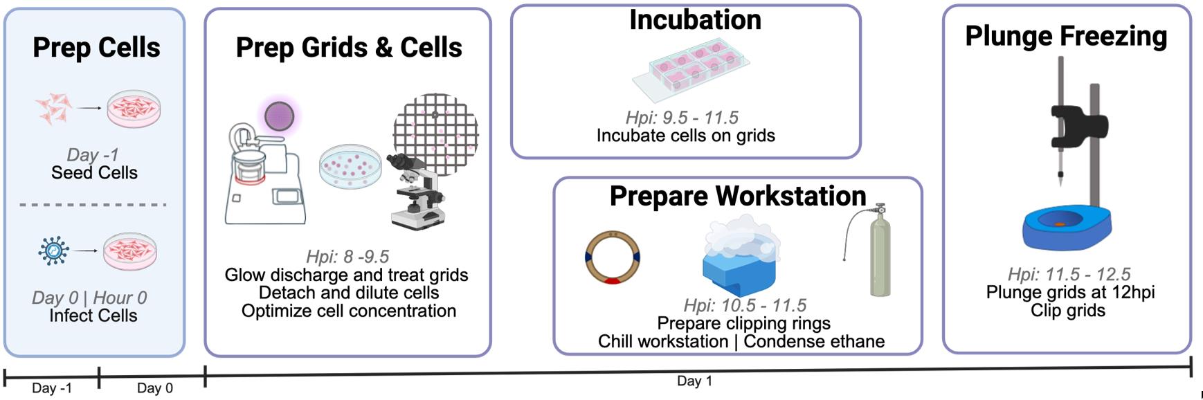
Schematic overview of sample and grid preparation for cryo-electron tomography (cryo-ET). This protocol provides detailed guidance on each critical step of preparation to increase the success of grid generation for plunge freezing. It requires three days from cell seeding to grid clipping and storage. Eight hours post-infection (hpi), users begin preparation for plunge freezing by transferring infected cells onto grids. From 9.5 to 11.5 hpi, users incubate cells on grids and set up the plunge freezer. In this protocol, cells are frozen at 12 hpi and then clipped.
Background
Cryo-focused ion beam (cryo-FIB) milling has dramatically expanded the targets accessible to cryo-electron tomography (cryo-ET) by enabling high-resolution imaging of the cellular interior. In particular, cryo-ET/FIB enables examination of virus-infected cells at an unprecedented level of detail [1–4]. Before the implementation of cryo-FIB, cryo-ET was largely limited to imaging peripheral regions of the cell. Access to the cellular interior, with limited sample distortion, permits researchers to determine the structures of key proteins in their native environment and provides insight into their cellular context. This access is crucial for studying viral replication and assembly in important cellular compartments, such as the nucleus. In the past five years, automation of FIB milling and data collection has increased the efficiency of this pipeline [5–7]. At the same time, software for cryo-ET data processing and analysis, such as RELION 5.0 [8] and AreTomo2 [9,10], has been introduced. Despite these advances on the processing end of the cryo-ET/FIB pipeline, sample preparation remains a major roadblock, especially for beginners. Sample preparation prior to cryo-FIB milling includes (1) seeding cells onto an EM grid and (2) freezing and clipping grids.
Success of cryo-ET requires thin, <200 nm lamellae produced by cryo-FIB milling. In turn, successful FIB milling requires a sample with optimal cell distribution on grids. Cell aggregation or excess buffer can increase sample thickness, requiring more time and a higher ion beam current on the dual-focused ion beam–scanning electron microscope (FIB-SEM), which can damage the cell. Therefore, it is critical to optimize cell seeding and grid blotting to maximize efficient use of dual-beam microscope time while ensuring cell integrity. This protocol focuses on the first two steps of sample preparation to prepare high-quality grids reproducibly for FIB-SEM.
Despite the existence of automated plunge freezers, such as Leica GP2 and ThermoFisher VitroBot, they may not be readily accessible to all interested users. Besides, manual plunge freezers offer some practical benefits. For instance, they are more portable, which is advantageous for users who work with BSL2-level samples and must plunge-freeze them inside a biosafety hood. In addition, they are more cost-effective, being typically 1/10th the price of automatic plunge freezers, making them accessible to more labs. Finally, manual plunge-freezing can be beneficial when working with fragile cells. However, manual plungers require more careful handling than automatic plungers to achieve high reproducibility. Poor handling can lower the number of grids suitable for milling.
This protocol was developed to prepare samples of mammalian cells infected with herpes simplex virus 1 (HSV-1) for cryo-FIB/ET to study a process termed “nuclear egress” that is unique to herpesviruses [11]. However, it can be readily adapted for use with uninfected mammalian cells after any treatment, such as chemical inhibitors. This protocol guides beginner-level users in how to seed infected cells onto grids, blot, and plunge-freeze grids using basic, manual equipment under BSL2 conditions. It emphasizes optimizations and provides troubleshooting suggestions for sample preparation. In our hands, the use of this protocol has drastically improved the yield of millable grids for cryo-ET/FIB. Published protocols that describe the use of a manual plunge freezer [12–15], handling liquid ethane [16], and using a clipping station [17] are important companions. Finally, protocols that provide guidance on growing cells on grids can be used in conjunction with this protocol [18–20].
Materials and reagents
Biological materials
1. Vero cells (ATCC, catalog number: CCL-81) or HeLa Cells (ATCC, catalog number: CCL-2)
Note: This protocol has been tested with both Vero and HeLa cells, but it could be applied to other adherent cells.
2. Herpes simplex virus 1 tdTomato-NLS (strain HSV-1 F-GS3217, which encodes a tdTomato-NLS fluorescent reporter under the control of a CMV promoter) (gift from Dr. Gregory Smith, Northwestern University)
Note: A strain encoding a fluorescent reporter enables the use of integrated fluorescence light microscopy (iFLM). Any HSV-1 or HSV-2 strain encoding a fluorescent reporter can be used instead of the one listed here. A strain lacking a fluorescent reporter can also be used, but without iFLM.
Reagents
1. Dulbecco’s modified Eagle’s medium (DMEM) (Cytiva, catalog number: SH30285.01); store at 4 °C
2. Penicillin-streptomycin solution, 100× (Cytiva, catalog number: SV30010); store at 4 °C
3. Fetal bovine serum (FBS), heat-inactivated (BioWest, catalog number: S1680-500); store at -20 °C
4. L-glutamine, 200 mM (Corning, catalog number: 25-005-CI); store at 4 °C
5. Phosphate-buffered saline (PBS), 1× (Cytiva, catalog number: SH30256.FS); store at room temperature
6. Trypsin, 0.05% protease solution (Cytiva, catalog number: SH30236.01); store at 4 °C
7. Trypan blue solution (Cytiva, catalog number: SV30084.01); store at room temperature
8. Poly-l-lysine solution, 0.1% (Sigma-Aldrich, CAS number: 25988-63-0); store at room temperature
9. Bleach (Clorox, catalog number: 30966); store at room temperature
Solutions
1. Complete DMEM (cell growth media) (see Recipes)
2. 20% (v/v) bleach (see Recipes)
3. 0.01% (v/v) poly-l-lysine (see Recipes)
Recipes
1. Complete DMEM (cell growth media)
| Reagent | Final concentration | Quantity or volume |
|---|---|---|
| DMEM | 1× | 440 mL |
| FBS | 10% | 50 mL |
| Penicillin-streptomycin solution, 100× | 1× | 5 mL |
| L-glutamine, 200 mM | 2 mM | 5 mL |
| Total | 500 mL |
Remove a 60 mL aliquot of DMEM from the 500 mL bottle before adding any components, save it, and label it as “serum-free DMEM.” Store complete DMEM at 4 °C for up to 3 months.
2. 20% (v/v) bleach
Prepare fresh. For 200 mL, mix 40 mL of undiluted bleach with 160 mL of water. Store in a plastic bottle.
3. 0.01% (v/v) poly-l-lysine
Prepare fresh. For 200 μL, mix 20 μL of 0.1% poly-l-lysine with 180 μL of filtered, deionized water.
Laboratory supplies
1. 35 mm × 10 mm polystyrene tissue culture–treated dishes (CELLTREAT, catalog number: 229635)
2. 40 μm cell strainers (NEST Scientific, catalog number: 258369)
3. 50 mL centrifuge tubes (CELLTREAT, catalog number: 229421)
4. 15 mL centrifuge tubes (CELLTREAT, catalog number: 229411)
5. 1.5 mL microcentrifuge tubes (Bio Plas, catalog number: 4030)
6. 150 mm × 20 mm polystyrene tissue culture–treated dishes (CELLTREAT, catalog number: 229651)
7. UltrAuFoil, R 2/2; Gold 200 mesh grids (Quantifoil, catalog number: Q250AR2A)
8. Hybrid grid box (NanoSoft, catalog number: 14021008)
9. Fisherbrand qualitative grade filter paper, P4 (FisherScientific, catalog number: 09-803-6D)
10. 8-well clear chamber slides (NEST Scientific, catalog number: 230108)
11. Dumont tweezers style N5 (Electron Microscopy Sciences, catalog number: 0203-N5-PO)
12. Spearlab Foam Dewar, standard vessel (MiTeGen, SKU: M-FD-800)
13. UN1977 liquid nitrogen (MedTech)
14. Ethane, research grade (AirGas, catalog number: ET RP35)
15. Brass gas regulator (AirGas, catalog number: Y12244A350-AG)
16. VWR® CryoGuard cryogenic gloves (VWR, catalog number: 97008-216)
17. Deluxe surgical mask (Uline, catalog number: S-22137)
18. Colored labeling tape (Fisher Scientific, catalog number: 15-901-R)
19. Heavy duct tape (Amazon, ASIN: B07WHV2F9C)
20. Autogrid tweezers (NanoSoft, catalog number: 23021002)
21. Pin lid manipulator tool (NanoSoft, catalog number: 27011001)
22. C-clips (NanoSoft, SKU: 11011002)
23. Cryo-FIB Autogrid Rings (Thermo Fisher Scientific, SKU: 1205101)
Note: Must be purchased directly from a Thermo Fisher representative; alternatives are available from Ted Pella/NanoSoft, but these should be discussed with EM core managers.
24. Colored cryo-markers, ethanol resistant (Electron Microscopy Sciences, catalog number: 62050)
25. Screwdriver for puck lid lock (MiTeGen, SKU: M-CEMG2-LLSD)
Equipment
1. Biosafety cabinet (Nuaire, model: NU-425-400)
2. CO2 cell culture incubator (Thermo Scientific, model: Heracell VIOS 160i)
3. Fluorescent microscope (Leica, model: DM IL LED)
4. Hausser Scientific phase hemacytometer (Fisher Scientific, catalog number: 02-671-10)
5. ZEROSTAT3 anti-static gun (Ted Pella, catalog number: 54610)
6. PELCO easiGlowTM glow-discharge system for cryo-EM (Ted Pella, catalog number: 91000S)
7. Liquid dewar (4 L) (MidSci, catalog number: Q250AR2A)
8. Manual plunge freezer, foot-pedal operation (Neptune Fluid Flow Systems, catalog number: MP1)
9. Vitrification dewar including metal parts (NanoSoft, catalog number: 21021006)
10. 10× magnifying glass with light and clamp (TOMSOO, Amazon, ASIN: B0B8RZWW8X)
11. Clipping station (NanoSoft, catalog number: 25011001)
12. 4-way flipper racks (ThermoFisher Scientific, catalog number: 8850)
13. Hair dryer (Amazon, ASIN: B00GUAEERO)
14. MiTeGen Cryo-EM Puck, generation 2.0 (MiTeGen, SKU: M-CEMG2-1)
Note: SubAngstrom also supplies cryo-EM pucks with distinct racks from MiTeGen. Contact your EM core to determine their storage preference.
15. Transport cane for Cyro-EM puck (MiTeGen, SKU: M-CEMTPC-1)
16. High-capacity (HC) liquid nitrogen refrigerator (MiTeGen, SKU: TW-HC34)
17. Aquilos Cryo-FIB (ThermoFisher)
Software and datasets
1. ThermoFisher xT (Beam control)
2. ThermoFisher Maps 3.21
Procedure
A. Prepare and infect cells
Note: Before handling grids, the virus and cells must be ready for use. This requires that the virus be titrated and aliquoted at a known titer; our purification and titration protocol is adapted from [21]. Viral titer must be measured as plaque-forming units per milliliter of stock (PFU/mL). This protocol assumes competence in tissue culture and general cell handling techniques. In this section, you will seed two plates (steps A1–2), determine the number of cells per plate and calculate virus required for infection (steps A3–12), infect cells (steps A13–14), allow virus to adhere for 1 h (step A15), and remove the virus and allow infection to proceed in the incubator (step A16–17).
1. Prepare two 10-cm dishes with cells. This allows you to use one dish for cell counting before infection. Each dish should be seeded with 2.2 × 10⁶ cells in 12 mL of complete DMEM (see Recipe 1).
Note: Cells should be at least one passage and less than six passages after thawing.
Caution: All work with cells and viruses should be carried out following BSL2 safety practices inside a biosafety cabinet.
2. Incubate cells at 37 °C with 5% CO2 for 12–18 h.
3. The next day, confirm that the cells are at least 80% confluent in the dish.
4. Aspirate media from one plate and rinse with 7 mL of PBS by gently pipetting over cells and aspirating.
5. Add 5 mL of trypsin and incubate the dish at 37 °C with 5% CO2 for 5 min until all cells are detached and floating in media.
6. Add 5 mL of complete DMEM to the dish and pipette up and down to break up cell clumps and release cells from the dish.
7. Pipette 25 μL of cells into a 1.5 mL Eppendorf tube.
8. Mix 75 μL of trypan blue with 25 μL of cell suspension.
9. Pipette 10 μL of this cell mixture into a hemocytometer.
10. Count the number of live (i.e., not trypan blue–positive) cells in each of the four border squares (also called 16 squares) and multiply by 10,000 to calculate the number of cells per milliliter in the solution. The factor of 10,000 corrects for the volume in the Neubauer grid, 1 × 10⁻⁴ mL. Multiply this value by 10 to determine the number of cells in the starting dish; this adjusts for the starting volume of 10 mL.
Template calculation:
11. Calculate necessary volumes for infecting cells at a multiplicity of infection (MOI; PFU/cell) of 5 using the known titer of your virus stock (PFU/mL). For accuracy, 1.5× of the total requisite volume is prepared.
a. Media calculation:
b. Virus calculation:
Caution: For best BSL2 practice, remove all unnecessary equipment from the TC hood before introducing the virus. Prepare a beaker with 20% bleach for all tips and waste (see Recipe 2).
12. Prepare the virus mixture. In a 15-mL tube, mix the volume of serum-free DMEM calculated in step A11a with the volume of viral stock calculated in step A11b.
13. Aspirate the media from the remaining 10-cm dish.
14. Pipette 2 mL of the virus mixture from step A12 onto the infection dish.
15. Place the 10-cm dish into a 15-cm dish and place both into a 4 °C fridge for 1 h, gently rocking by hand every 15 min.
Note: Infected cells are placed into a 15-cm dish to serve as secondary containment in the communal fridge and incubator.
16. After 1 h, aspirate the virus gently and add 12 mL of complete DMEM.
Note: This marks the start of the infection.
17. Return the cells to the incubator and allow infection to proceed.
B. Grid preparation and seeding
Note: In this section, you will glow-discharge and treat grids (steps B1–7 and B18–21), calculate the density of infected cells (steps B8–17), and incubate grids with cells (steps B22–27).
Critical: Grid preparation must be started by 8 hpi or 4 h before the infection time point.
1. Place 4–8 grids, mesh side up, onto the glow-discharge holder. Glow-discharge grids for 120 s at 30 mA with negative charge.
Note: While users should determine their own grid handling efficiency, we recommend starting with four to six grids because one or two grids will likely be broken during handling or freezing. Users should avoid trying to freeze more grids at a time because liquid nitrogen and ethane accumulate ice and evaporate over time.
Caution: Always use gloves when handling components that enter the glow-discharge chamber.
Critical: Glow-discharging the grids is required for successful cell adherence. This process renders the EM grid mesh surface hydrophilic for sample addition.
2. Place glow-discharged grids into a 10-cm dish to transfer them from the glow discharger to the tissue culture hood.
Notes:
1. Static between the grids and the tissue culture dish can pose an issue. Using antistatic guns against the bottom of the tissue culture dish may help reduce static charge. Alternatively, lightly wiping the bottom of the dish with 70% ethanol on a Kimwipe can help.
2. Think about how you will remove the grids from the dish before placing them—provide adequate space for the tweezers to reach each grid.
3. Prepare poly-l-lysine (PLL) solution (see Recipe 3).
Note: Always freshly prepare the PLL before use. PLL promotes cell adhesion to the grid.
4. Pipette 20 μL of PLL solution onto each grid, forming a dome over the mesh.
5. Cover the dish with a lid and place the grids under UV light for 30 min.
6. Prepare a “cleaning plate” to rinse the grids after PLL treatment. Place 50 μL droplets of complete DMEM (see Recipe 1) onto a 10-cm plate in an array. Prepare three droplets per grid (i.e., 12 total droplets for 4 grids).
7. Prepare an 8-well chamber slide by pipetting 50 μL of complete DMEM (see Recipe 1) into each well.
Notes:
1. Different conditions cannot be included in the same 8-well chamber slide, as the contents of the 8 wells are mixed in section D (due to the removal of the upper chamber). Use separate slides for different conditions.
2. Handle the chamber gently to maintain the droplet integrity. The droplet height assists with depositing the grid.
8. Remove infected cells from the incubator (step A17) at 9 hpi and confirm infection by TdTomato signal.
Note: At least 70% of cells should be positive for fluorescent signal. In the absence of a fluorescent reporter, observing cytopathic effects (i.e., the rounding up of cells) can be used to confirm infection.
Critical: Cells must be prepared at 9 hpi or 3 h before the infection time point.
Caution: Before placing infected plates into the hood, remove excess materials and place a beaker with 20% bleach (see Recipe 2) inside for BSL2 inactivation.
9. Aspirate the media and rinse gently with 5 mL of PBS.
Caution: Infected cells are much more fragile than uninfected cells. Set the pipettor to the lowest setting and be careful when aspirating liquid.
10. Aspirate the PBS. Add 5 mL of trypsin to the dish and incubate at 37 °C with 5% CO2 for 5 min.
11. Following trypsinization, add 5 mL of complete DMEM to the dish and carefully pipette up and down to break up cell clumps and release cells from the dish.
12. Pre-wet a 40-μm cell filter membrane with 1 mL of complete DMEM and place it into a 50-mL Falcon tube.
13. Slowly pipette resuspended cells through the filter. Dispose of the filter in 20% bleach.
14. Pipette 25 μL of filtered cells into a 1.5-mL Eppendorf tube.
15. Mix 75 μL of trypan blue with the 25 μL of filtered-cell suspension.
16. Pipette 10 μL of this cell mixture into a cell counting slide. Count the total number of live cells from all four border squares and multiply by 10,000 to calculate the number of cells per milliliter in the solution. Multiply by 10 to determine the number of cells in the starting dish.
17. Dilute cells to 1 × 10⁴ cells/mL with complete DMEM into 5 mL of total volume.
18. Prepare your workspace (see Figure 1). Make a place for the PLL-treated grids on the far-left side of the hood, place the “cleaning plate” centrally, and the 8-well chamber slide on the right (for right-handed users). Elevating plates and chamber slides on tip boxes or a stack of 4-way racks can help improve grid handling, especially for taller users.
19. Upon completion of the 30-min UV treatment (from step B5), rinse grids by gently passing them through three droplets of complete DMEM. Ensure minimal contact between the tweezers and the droplet.
20. Place the cleaned grid on top of the 50-μL droplet in the chamber slide.
21. Repeat steps B19–20 for all grids.
22. Resuspend the cell mixture (from step B17) by gently pipetting up and down.
23. Add 150 μL of cells to the grid and 50 μL of complete DMEM to one well and bring it to the microscope.
24. Allow cells to settle for 5 min, then observe the number of cells sitting in wells by eye.
25. Adjust the cell density such that approximately every square receives 1–2 cells.
Notes:
1. If the cell mixture is too dense, start with half of the starting cell density and observe if the number of cells reduced corresponds with a 2-fold reduction in cell density.
2. To help gauge the cell density, use old or bad grids with the same mesh count to avoid wasting grids.
Critical: Achieving good cell density is critical, as too high cell density will cause grids to be too thick, whereas too low cell density will not yield enough targets for milling. Sufficient cell density will need to be optimized by each user by screening using SEM.
26. Prepare the rest of the grids with the optimized cell density.
27. Place the 8-well chamber into a 10-cm dish and return to the incubator to allow cells to adhere for 2 h.
Note: The time for cell adherence is cell-type specific. Monitor cells under the microscope every 30 min to observe if cells have lost their roundedness and have begun attaching to grids.
Critical: Cell adherence and survival on grids is critical for the success of the protocol. See Troubleshooting.

Figure 1. Recommended workplace organization for grid seeding. To optimize efficiency with grid handling, organizing the three plates in the hood from left to right—treated grids, cleaning plate, and 8-well chamber—is recommended. The “treated grids” plate contains grids that are arranged at the center of the plate for easy tweezer access. The “cleaning plate” contains an equally spaced grid of droplets of complete DMEM, three per grid. The “8-well chamber” slide is prepared with droplets of media in each well, which provide a pedestal to lay grids on before applying cells.
C. Preparation for plunge freezing and grid clipping
Note: Setting up an ergonomic workspace around the manual plunge freezer is critical for successful plunge freezing. Before starting the procedure, it is highly recommended to review available video protocols for setting up [12–14] and operating the manual plunge freezer [15].
1. Test the distance of the tension cable. A firm press on the foot pedal should release the arm. Once the appropriate distance between the foot pedal and the plunge freezer is established, tape down the foot pedal to the floor and the base of the plunge freezer to the bench top.
2. Center the vitrification dewar under the plunge freezer arm. Test the height of the arm with damaged or otherwise disposable tweezers. After adjusting the height, place fresh lab tape onto the post that holds the tweezers.
Note: Grids should be fully submerged below the lip of the brass cup, but the tweezers should enter ethane as little as possible. Verify the height 3–4 times, ensuring a quick depression of the foot pedal plunges the tweezers toward the center of the brass cup.
3. Prepare auto-rings by coloring engraved dots and beam divot. These markings facilitate orienting grids for FIB-SEM. See Figure 2.
4. Prepare blotting paper by tearing P4 filter paper into 3–4 long strips.
Note: We recommend tearing the filter paper, instead of using scissors, because tearing generates the rough, fibrous edges that help wick the liquid from the back of the grid.
5. Load C-clips into C-clip tools. Use a thicker tweezer to pick up the C-clip at the curve of the C. Turn the C-clip tool so the opening faces you. Press the C-clip into the tool. Using a smaller tweezer, push the edge of the C so that it is turned flat against the tool opening.
6. Gently place the C-clip tool against a clean, flat surface and press down firmly. Check that the C-clip is flush against the edge.
Break point: The protocol can be paused here until the user is ready to start section D. Start section D no later than 30 min before the cells are ready to go.
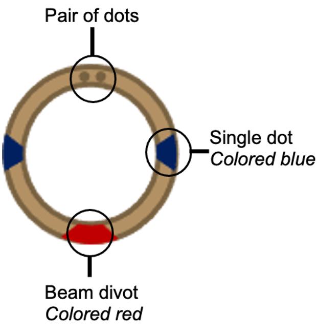
Figure 2. Annotation of FIB-SEM auto-ring. The focused ion beam–scanning electron microscope (FIB-SEM) used for screening and milling requires the grid to be clipped into a designated auto-ring. On the top face of the ring, there are four visible engravings. Two single dots are opposed. Mark the top face and edge of the ring at each dot with a blue permanent marker. Situated 90° between the single dots lies an engraved divot, through which the FIB beam passes, and a pair of dots. Color the divot with red permanent marker.
D. Plunge freezing
Note: Wearing a surgical mask while working with liquid nitrogen and ethane can help minimize water contamination. All equipment and tools (i.e., tweezers, screwdriver tips, grid boxes) should be pre-cooled in liquid nitrogen before use.
Caution: Working with liquid nitrogen and liquid ethane requires specialized training. As liquid nitrogen and liquid ethane can potentially be dangerous, personal protective equipment (i.e., cryo-gloves, lab coats, and protective glasses) should be used. Coordinate with your local Environment, Health, and Safety (EHS) office and review safe handling guidance [16].
1. When 30 min remain in the infection time course (i.e., 11.5 hpi), fill two 4-L dewars with liquid nitrogen.
2. Fill a foam dewar with liquid nitrogen and use it to cool a 50-mL Falcon tube and rack. Replenish liquid nitrogen levels until all components have reached the temperature of liquid nitrogen (i.e., when bubbling has stopped).
3. Under the fume hood, condense ethane. Empty and secure the cooled 50-mL Falcon tube in the rack. Place the ethane tubing with a pipette tip against the side of the Falcon tube. Slowly open the ethane gas and regulate to ~5 PSI or lower.
Caution: Liquid ethane is flammable and will burn skin on contact. Work with EHS to prepare your workstation to be as safe as possible.
Note: You must use a separate foam dewar from the vitrification dewar described in step D5.
4. Gently move the tip of the ethane tubing along the side of the Falcon tube and listen for the sounds of liquid splashing. Check that the tip does not freeze solid. Stop the flow when at least 10 mL of liquid ethane has condensed. Cover the tube with a lid, but do NOT close the lid. Store condensed ethane in the foam dewar with liquid nitrogen until ready for use.
Caution: When condensing ethane, the ethane can solidify at the end of the tip where gas is released. This will stop gas flow and cause pressure buildup in the tubing. If gas stops flowing, turn off the flow and remove the tip from the vapor phase so it can thaw.
5. Place 1–2 hybrid grid boxes within the vitrification dewar and note their numbers and colors for sample tracking. See Figure 3A for assistance in identifying the metal parts within the vitrification dewar.
6. Chill the vitrification dewar, including the brass cup, metal spider, and grid boxes, with liquid nitrogen.
7. When all metal parts reach liquid nitrogen temperature (i.e., no boiling occurs), fill the outer ring of the vitrification dewar with liquid nitrogen to the top of the metal grid box holder. Ensure the brass cup no longer contains liquid nitrogen.
Notes:
1. Using Styrofoam cups can help with pouring small volumes of liquid nitrogen.
2. If a small volume of liquid nitrogen remains in the brass cup, the back end of a warm, dry pair of tweezers can be used to boil it off.
8. Carefully transfer the liquid ethane from the 50-mL Falcon tube into the brass cup in the center of the vitrification dewar. Pour slowly, as vapor obscures the view, to avoid overfilling the brass cup.
Note: Ethane will freeze solid when left in liquid nitrogen. Gently swirl the tube to promote thawing before pouring into the brass cup.
9. Replenish the liquid nitrogen level as needed and place a lid over the vitrification dewar. Allow the ethane to cool to the temperature for 5 min.
10. While the ethane cools, prepare a beaker for BSL2 waste. Using stacked tip boxes, elevate the 8-well chamber slide to a good working height. Place the 8-well chamber slide inside a 10-cm dish to manage any spills.
Caution: Follow BSL2 procedures when working with virus-infected cells.
11. Crack the upper casing off the 8-well chamber slide, keeping the rubber edging if possible.
12. Check the ethane for frosting along the edges of the cup. The sides of the brass cup should appear frosted. Do not let the ethane freeze over the top of the brass cup, however. Break up any frozen ethane with dry tweezers. Replenish liquid nitrogen levels as necessary.
13. With tweezers, pick up the edge of a grid, using the footprint of the wells or the curve of the meniscus to assist. Be careful not to damage the grid mesh.
Critical: When handling grids, be careful to lift them cell-side up.
14. Place the tweezers on the bench with the grid facing cell-side up. Pipette 5 μL of the supernatant media onto the grid.
Note: We have found that adding 5 μL of media helps with blotting consistency.
15. Carefully tape the tweezers onto the manual plunger, with the cell side of the grid oriented toward you. Ensure the tweezers are centered above the ethane cup.
16. Blot the grid from behind, on the non-cell side (see Figure 3C). To do this, bend a thin strip of filter paper toward the grid and slowly bring it toward the grid until it contacts the droplet of media. Hold the paper until the water tension between the grid and the paper breaks.
Critical: Blotting by eye rather than time has a significant impact on grid quality. If any media remains visible after the water tension between the media droplet and filter paper breaks, or if a hand movement pulls the paper away from the grid, gently tap the grid corner with the edge of a piece of filter paper (~2 s).
Caution: Used filter paper should be discarded in the BSL2 waste.
17. Quickly, but gently, tap the floor pedal to plunge the tweezers into the liquid ethane.
Critical: Move carefully and quickly to prevent cells from drying once removed from media.
18. Holding the tweezers steady in one hand and keeping the grid submerged in liquid ethane, detach the tweezers from the post by peeling back the tape.
19. Slowly raise the grid, forming a convex meniscus of liquid ethane around the grid.
20. Quickly lift the grid and move it into the liquid nitrogen in the outer ring of the vitrification dewar.
21. Gently place the grid into a grid box with the cell side facing the notch of the box.
22. Submerge the tweezers in 100% ethanol and dry.
23. Repeat steps D12–22 for each grid, replenishing the liquid nitrogen and ethane levels as necessary. To keep the ethane cup frosted during plunge-freezing, replenish liquid nitrogen as needed.

Figure 3. Demonstration of optimal blotting technique. (A) Orientation of the vitrification dewar and its metal parts. In yellow is the spider, which is removed after cooling. In red is the grid box holder. (i) central brass cup; (ii) outer ring of the vitrification dewar, which should be filled with liquid nitrogen. (B) Another view of the vitrification dewar. The outer ring contains liquid nitrogen, covering the metal grid box holder. Two grid boxes are visible on the holder. The brass cup is held in the center and contains well-frosted (i.e., properly cooled) ethane. (C) Workspace setup highlighting a well-positioned light source in the upper-left-hand corner and tweezers positioned centrally over the ethane cup with the cells facing the user. The inset shows a blotting technique with curved blotting paper approaching the grid back.
E. Grid clipping
Note: This protocol was optimized for the NanoSoft clipping station (see Equipment). A video from the manufacturer is available to guide use [17]. Wearing a surgical mask while working with liquid nitrogen and ethane can help minimize water contamination. All equipment and tools should be pre-cooled in liquid nitrogen before use. After being removed from liquid nitrogen, each tool must be dried completely before being re-submerged into the liquid nitrogen.
Caution: Working with liquid nitrogen requires specialized training. As liquid nitrogen can potentially be dangerous, personal protective equipment (i.e., cryo-gloves, lab coats, and protective glasses) should be used. Coordinate with your local Environment, Health, and Safety (EHS) office.
1. Replenish the liquid nitrogen level in the vitrification dewar and cover with a lid.
2. Chill the clipping station dewar, with all metal parts, including clipping pens, placed inside. Ensure the left side of the flipping mechanism is closest to the metal base. Continuously replenish the liquid nitrogen level until all boiling stops and the liquid level reaches the bottom of the metal components.
3. Transfer grid boxes from the vitrification dewar into the clipping station dewar using a pre-cooled pin-lid manipulator tool.
4. Using the pin-lid manipulator tool, unscrew the grid box lid and then screw the lid into the neighboring hole to stabilize the grid box in place.
5. Place an auto-grid ring colored-side down into the shallow hole.
6. Lift a single grid from the grid box and place it cell-side down into the ring.
Note: Clipping in the vapor phase (i.e., where the metal base is not submerged in liquid nitrogen) can help with maneuvering the grids from the clipping indentation to the box because the grids will float in liquid nitrogen.
7. Carefully, press the auto-grid tweezers into the right side of the cantilever beam to shift the guidance cylinder over the grid.
Note: You should not face any resistance at this stage. If you feel resistance, the grid is bent or out of alignment with the ring.
8. Lower a clipping pen into the hole and press it down. Firmly press the top of the clipping pen once to release the clip.
9. Remove the clipping pen. Using the auto-grid tweezers, flip the stage back to the open position.
10. Using the auto-grid tweezers, lift the clipped grid and place it in the test divot. Flip the grid back and forth three times to confirm its integrity. If the ring and grid stay together, return the clipped grid to the auto-grid side of the grid box. If the ring and grid fall apart, the clip was not properly inserted. Redo the clipping.
Note: To prevent damage to the grid, use auto-grid tweezers to clamp the entire clipped grid. As the auto grid rings are wider than the grid itself, this technique allows for easy grid handling.
11. Repeat steps E5–10 for each grid.
12. Pre-cool a cryo-EM grid storage puck in liquid nitrogen.
13. Using a pre-cooled screwdriver, lower the screw (located above the grid box slot #3) to rotate the clear lid.
14. Using a pre-cooled pin-lid manipulator tool, screw the lid onto the grid box and then transfer the grid box into a slot in the cryo-EM grid storage puck. Repeat this step as necessary for all grid boxes to store.
15. Use the screwdriver to rotate the clear lid back and secure the screw above the grid box slot #3. Transfer the cryo-EM grid storage pucks into a cane within a storage dewar.
F. Grid screening
Note: The Aquilos cryo-FIB-SEM dual-beam is the best tool for evaluating grids before milling. Users must follow facility-specific instructions for microscope preparation, alignment, and loading/unloading.
1. Following microscope cooling/purging and loading, navigate to Grid 1 in the microscope xT software.
2. Adjust the electron beam to 5 kV and 25 pA and the lowest magnification.
3. Use live view to quickly obtain a snapshot of the grid. Double-click at the grid center to move the stage to center the grid.
4. Apply a reduced view and adjust the focus on the visible grid mesh, slowly increasing the zoom until the edges of the mesh holes are crisp.
5. Set the working height by selecting Link Z to FWD.
6. Return to low magnification and launch Maps from the xT software.
7. Take a snapshot of the grid in Maps.
8. Add a tile set with high voltage (5 kV) selected and 1 µs dwell time. Select auto-focus, auto-contrast, and brightness on the first tile.
9. Overlay the tile set such that the center of the grid is covered, but do not collect the outermost squares, as these are not accessible to the FIB beam or on TEM. Confirm the first grid square is adequate for auto-focusing and contrast (i.e., free of ice or deformations).
10. Press Start to run the tile set.
11. Recenter on Grid 2 and repeat.
12. Assess grids for quality. Good grids should contain (1) visible mesh, (2) minimal grid distortion/bending, (3) 1–2 cells per grid square in the region >3 squares from the edge, and (4) hydrated cells (i.e., maintain appropriate height, 10–20 μm) but with minimal buffer around their footprint.
Note: Grid bars are trapezoidal and extend below the mesh. Therefore, cells are best situated >5 μm from the visible bar.
Validation of protocol
Out of 12 grids prepared using this protocol, 9 grids yielded lamellae for data collection. Each grid contained between 4 and 14 lamellae. Lamella were milled following published protocols [20]. To demonstrate the applicability of this protocol, we have also shown that this protocol works for infected Vero and HeLa cells (Figure 4B).
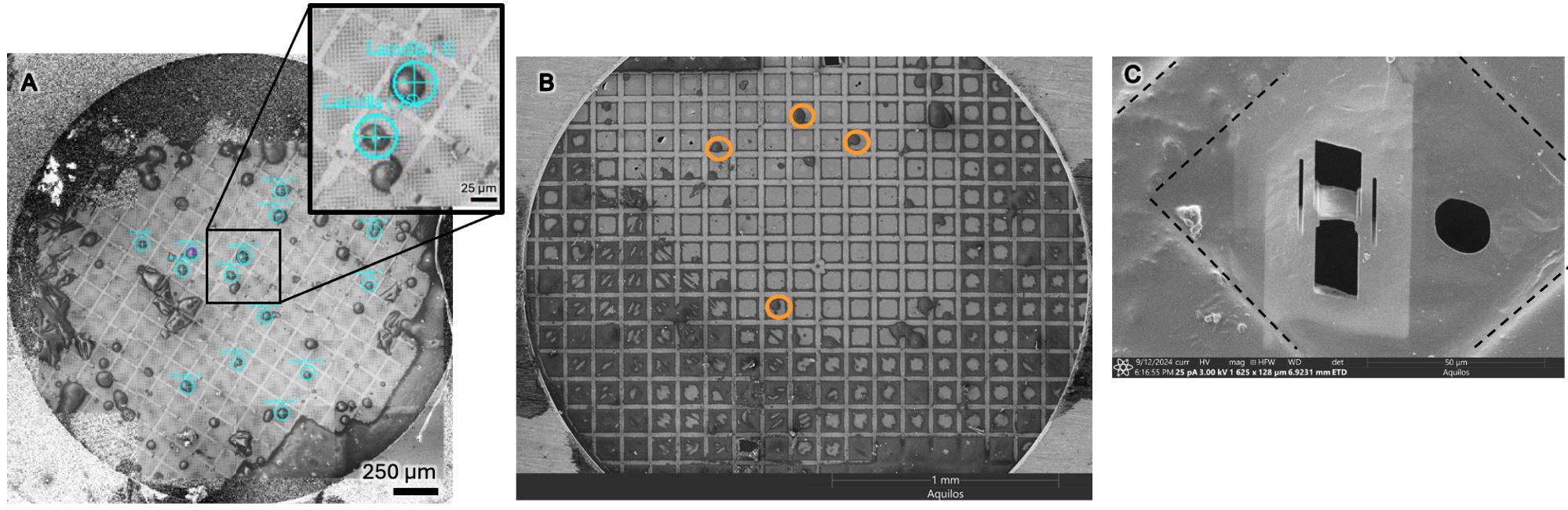
Figure 4. Grids were successfully prepared with Vero and HeLa cell types for efficient milling. (A) Grid prepared with Vero cells, where each teal target indicates a cell successfully milled. This represents the upper end of grid seeding density with 14 lamellae generated. Scale bar, 250 μm. The inset shows a magnification, showing two cells near the grid center. (B) A successfully prepared grid of HeLa cells, representing the lower end of grid seeding density. Cells that are well placed for milling are indicated by orange circles. Scale bar, 1,000 μm. (C) Final product of milling: a 200-nm-thin lamella of a single cell with dashed lines indicating grid bars. Scale bar, 50 μm.
General notes and troubleshooting
General notes
1. This protocol does not provide details on FIB milling, but many such protocols exist. In particular, we use the milling parameters from [20].
2. This protocol uses a manual plunge freezer, in contrast to automatic plunge freezing apparatuses. ThermoFisher VitroBot series of automatic plunge freezers applies a set “blot force” and blotting time, which are optimized for each sample and machine-dependent. This tool contains two blotting arms, requiring users to replace the filter paper on the cell-facing blot arm with Teflon or Parafilm and blot with the grid back-facing arm. How blot force pressure affects cells is unclear. However, over-blotting can alter cell morphology [18]. The Leica GP2 automatic plunge-freezer uses an optical sensor that responds to liquid absorption by the filter paper and performs single-sided blotting. For new users, those without access to cryo-EM core facilities, or those working under BSL2 conditions, we have found the manual plunge freezer to be a great tool. In particular, mimicking the GP2 “optical sensor” by monitoring media absorption onto the filter paper in place of a stringent blot time has greatly improved the reproducibility of grids.
3. Previously published protocols involved growing cells on grids [18,22]. However, we have found that growing cells on grids makes it difficult to accurately count the number of cells for infection because some cells may fail to attach or even die. Likewise, other researchers have described using a “deposition” approach where 5–10 μL of a cell suspension is deposited immediately before plunge freezing. These protocols do not include an incubation period and require constituting cells at high concentration in a low volume. We have found that this high concentration, required to obtain many targets on a grid, resulted in aggregation of cells at the center of the grid.
Troubleshooting
Problem 1: Insufficient number of targets (cells) on grids.
Possible cause 1: Cells did not adhere to the grids.
Solution 1: Test fibronectin and varying concentrations of PLL, increase adherence time, and reduce the volume of cells during grid attachment.
Possible cause 2: Cells were applied to the wrong side of the grid.
Solution 2: It is possible to clip grids in the opposite orientation if cells appear to be on the wrong side. However, milling around the grid bars is difficult. Keep track of the cell/mesh side of the grid.
Possible cause 3: Not enough cells applied to the grid.
Solution 3: Test a range of cell densities within at least a 2-log range and screen by SEM.
Problem 2: Grids look too thick.
Possible cause 1: Blotting was incomplete.
Solution 1: After the droplet between the back of the grid and the blot paper breaks, gently tap a fresh corner of the blot paper against the back of the grid to dry it a little more.
Possible cause 2: The media supernatant contained too many dead cells or other debris.
Solution 2: In step D14, apply fresh media to the grid before blotting instead of supernatant.
Acknowledgments
Conceptualization, N.L.; Investigation, N.L.; Writing—Original Draft, N.L.; Writing—Review & Editing, E.E.H.; Funding acquisition, E.E.H.; Supervision, E.E.H.
The present protocol was developed based on methods described in Franken et al. [18], Peterl et al. [19], Wagner et al. [20], and Hampton et al. [22].
This protocol was developed in the Heldwein laboratory at Tufts University School of Medicine. We thank the New York Structural Biology Center for training, Dr. Daniel Asarnow (University of Washington) for guidance on manual blotting technique, Drs. Stefan L. Oliver and Lydia-Marie Joubert (Stanford University; SLAC) for guidance on cell attachment, the Harvard Cryo-ET Users Group for helpful feedback, and Ariana Calkwood Calderon-Zavala for protocol feedback. This work was performed in part at the MIT.nano core facility. We thank Drs. Jenn Podgorski and Sarah Sterling from MIT.nano for maintenance of and assistance with the Aquilos. Some of this work was performed at the Stanford-SLAC CryoET Specimen Preparation Center (SCSC), which is supported by the National Institutes of Health Common Fund Transformative High Resolution Cryoelectron Microscopy program (U24GM139166). We thank Drs. Chensong Zhang and Lydia Marie-Joubert (SCSC) for their invaluable support and assistance. Some FIB-SEM data were collected at the Molecular Electron Microscopy Suite at Harvard Medical School. We thank Dr. Conny Leistner (HMS) for the maintenance of the Aquilos I/II and organization of the cryo-ET Users Group. This work was supported by the National Institutes of Health under Award Number R01AI147625 (E.E.H.), by a Faculty Scholar grant 55108533 from the Howard Hughes Medical Institute (E.E.H.), and by the Pew Innovation Fund award 34472 from the Pew Charitable Trusts. The content is solely the responsibility of the authors and does not necessarily represent the official views of the National Institutes of Health, the Howard Hughes Medical Institute, or the Pew Charitable Trusts.
The following figures were created using BioRender: Graphical overview and Figure 1. The graphical overview was created in BioRender. Lavoie, N. (2025) https://BioRender.com/xwznk32; Figure 1 was created in BioRender. Lavoie, N. (2025) https://BioRender.com/sccq2ya.
Competing interests
The authors declare no conflicts of interest.
References
- Zhou, Q. and Lok, S. M. (2024). Visualizing the virus world inside the cell by cryo-electron tomography. J Virol. 98(12): e01085–23. https://doi.org/10.1128/jvi.01085-23
- Graham, M. and Zhang, P. (2023). Cryo-electron tomography to study viral infection. Biochem Soc Trans. 51(4): 1701–1711. https://doi.org/10.1042/bst20230103
- Quemin, E. R., Machala, E. A., Vollmer, B., Pražák, V., Vasishtan, D., Rosch, R., Grange, M., Franken, L. E., Baker, L. A., Grünewald, K., et al. (2020). Cellular Electron Cryo-Tomography to Study Virus-Host Interactions. Annu Rev Virol. 7(1): 239–262. https://doi.org/10.1146/annurev-virology-021920-115935
- Zimmermann, L. and Chlanda, P. (2023). Cryo-electron tomography of viral infection — from applications to biosafety. Curr Opin Virol. 61: 101338. https://doi.org/10.1016/j.coviro.2023.101338
- Eisenstein, F., Yanagisawa, H., Kashihara, H., Kikkawa, M., Tsukita, S., and Danev, R. (2022). Parallel cryo electron tomography on in situ lamellae. Nat Methods. 20(1): 131–138. https://doi.org/10.1038/s41592-022-01690-1
- Turk, M. and Baumeister, W. (2020). The promise and the challenges of cryo‐electron tomography. FEBS Lett. 594(20): 3243–3261. https://doi.org/10.1002/1873-3468.13948
- Zachs, T., Schertel, A., Medeiros, J., Weiss, G. L., Hugener, J., Matos, J. and Pilhofer, M. (2020). Fully automated, sequential focused ion beam milling for cryo-electron tomography. eLife. 9: e52286. https://doi.org/10.7554/elife.52286
- Burt, A., Toader, B., Warshamanage, R., von Kügelgen, A., Pyle, E., Zivanov, J., Kimanius, D., Bharat, T. A. M. and Scheres, S. H. W. (2024). An image processing pipeline for electron cryo‐tomography in RELION ‐5. FEBS Open Bio. 14(11): 1788–1804. https://doi.org/10.1002/2211-5463.13873
- AreTomo2. (2023). Chan Zuckerberg Institute for Advanced Biological Imaging. Retrieved from https://github.com/czimaginginstitute/AreTomo2/tree/main
- Zheng, S., Wolff, G., Greenan, G., Chen, Z., Faas, F. G., Bárcena, M., Koster, A. J., Cheng, Y. and Agard, D. A. (2022). AreTomo: An integrated software package for automated marker-free, motion-corrected cryo-electron tomographic alignment and reconstruction. J Struct Biol: X. 6: 100068. https://doi.org/10.1016/j.yjsbx.2022.100068
- Draganova, E. B., Thorsen, M. K. and Heldwein, E. E. (2021). Nuclear Egress. Curr Issues Mol Biol. 41: 125–170. https://doi.org/10.21775/cimb.041.125
- McQueen, T. (Director). (2023, February 23). Assembly of main body of plunge freezer. YouTube. Retrieved from https://www.youtube.com/watch?v=fLAYRBv7y7Y
- McQueen, T. (Director). (2023, February 23). Foot Pedal assembly and tensioning. YouTube. Retrieved from https://www.youtube.com/watch?v=8NRQFXtYnTU
- McQueen, T. (Director). (2023, February 23). How to thread the tension cable. YouTube. Retrieved from https://www.youtube.com/watch?v=RZXioi7iuqU
- Nguyen, H. P. M., McGuire, K. L., Cook, B. D. and Herzik, Jr., M. A. (2022). Manual Blot-and-Plunge Freezing of Biological Specimens for Single-Particle Cryogenic Electron Microscopy. J Visualized Exp. 180: e3791/62765–v. https://doi.org/10.3791/62765-v
- Klein, R. C., Lewchik, B. and White, S. (2019). Safe plunge freezing. J Chem Health Saf. 26(2): 38–43. https://doi.org/10.1016/j.jchas.2018.11.002
- NanoSoft (Director). (2022, September 29). NanoSoft Clipping Station. YouTube. Retrieved from https://youtu.be/RWSu24rXjoE
- Franken, L. E., Rosch, R., Laugks, U. and Grünewald, K. (2022). Protocol for live-cell fluorescence-guided cryoFIB-milling and electron cryo-tomography of virus-infected cells. STAR Protoc. 3(4): 101696. https://doi.org/10.1016/j.xpro.2022.101696
- Peterl, S., Wachsmuth-Melm, M. and Chlanda, P. (2025). Sample Preparation for Cryo-Electron Tomography of Influenza A Virus and Infected Cells. Methods Mol Biol. 2890: 169–184. https://doi.org/10.1007/978-1-0716-4326-6_9
- Wagner, F. R., Watanabe, R., Schampers, R., Singh, D., Persoon, H., Schaffer, M., Fruhstorfer, P., Plitzko, J. and Villa, E. (2020). Preparing samples from whole cells using focused-ion-beam milling for cryo-electron tomography. Nat Protoc. 15(6): 2041–2070. https://doi.org/10.1038/s41596-020-0320-x
- Sutter, S. O., Marconi, P. and Meier, A. F. (2019). Herpes Simplex Virus Growth, Preparation, and Assay. Methods Mol Biol. 2060: 57–72. https://doi.org/10.1007/978-1-4939-9814-2_3
- Hampton, C. M., Strauss, J. D., Ke, Z., Dillard, R. S., Hammonds, J. E., Alonas, E., Desai, T. M., Marin, M., Storms, R. E., Leon, F., et al. (2016). Correlated fluorescence microscopy and cryo-electron tomography of virus-infected or transfected mammalian cells. Nat Protoc. 12(1): 150–167. https://doi.org/10.1038/nprot.2016.168
Article Information
Publication history
Received: Oct 9, 2025
Accepted: Dec 1, 2025
Available online: Dec 16, 2025
Published: Jan 5, 2026
Copyright
© 2026 The Author(s); This is an open access article under the CC BY-NC license (https://creativecommons.org/licenses/by-nc/4.0/).
How to cite
Lavoie, N. R. and Heldwein, E. E. (2026). Reproducible Sample Preparation of Virus-Infected Cells for Cryo-FIB/ET Using Manual Plunge Freezing. Bio-protocol 16(1): e5563. DOI: 10.21769/BioProtoc.5563.
Category
Microbiology > Microbial cell biology > Cell-based analysis
Cell Biology > Cell imaging
Biophysics > Electron cryotomography
Do you have any questions about this protocol?
Post your question to gather feedback from the community. We will also invite the authors of this article to respond.