- Protocols

- Articles and Issues
- For Authors
- About
- Become a Reviewer

Using a Live Analysis System to Study Amyloplast Replication in Arabidopsis Ovule Integuments
Published: Vol 15, Iss 11, Jun 5, 2025 DOI: 10.21769/BioProtoc.5333 Views: 2852
Reviewed by: Ansul LokdarshiSriema L. WalawageWenyang Li
Original research article
The authors used this protocol in:
Jun 2024
Advertisement


Protocol Collections
Comprehensive collections of detailed, peer-reviewed protocols focusing on specific topics


Abstract
Amyloplasts, non-photosynthetic plastids specialized for starch synthesis and storage, proliferate in storage tissue cells of plants. To date, studies of amyloplast replication in roots and the ovule nucelli from various plant species have been performed using electron and fluorescence microscopy. However, a complete understanding of amyloplast replication remains unclear due to the absence of experimental systems capable of tracking their morphology and behavior in living cells. Recently, we demonstrated that Arabidopsis ovule integument could provide a platform for live-cell imaging of amyloplast replication. This system enables precise analysis of amyloplast number and shape, including the behavior of stroma-filled tubules (stromules), during proplastid-to-amyloplast development in post-mitotic cells. Here, we provide technical guidelines for observing and quantifying amyloplasts using conventional fluorescence microscopy in wild-type and several plastid-division mutants of Arabidopsis.
Key features
• Novel approach for investigating amyloplast differentiation and replication in plant cells.
• Detection of stroma-labeled amyloplasts in whole-mount ovules using conventional fluorescence microscopy.
• Facilitates quantitative and comparative analysis of amyloplast proliferation using various Arabidopsis resources.
• Enables high-resolution analysis of changing amyloplast and stromule morphologies in living cells.
Keywords: AmyloplastGraphical overview
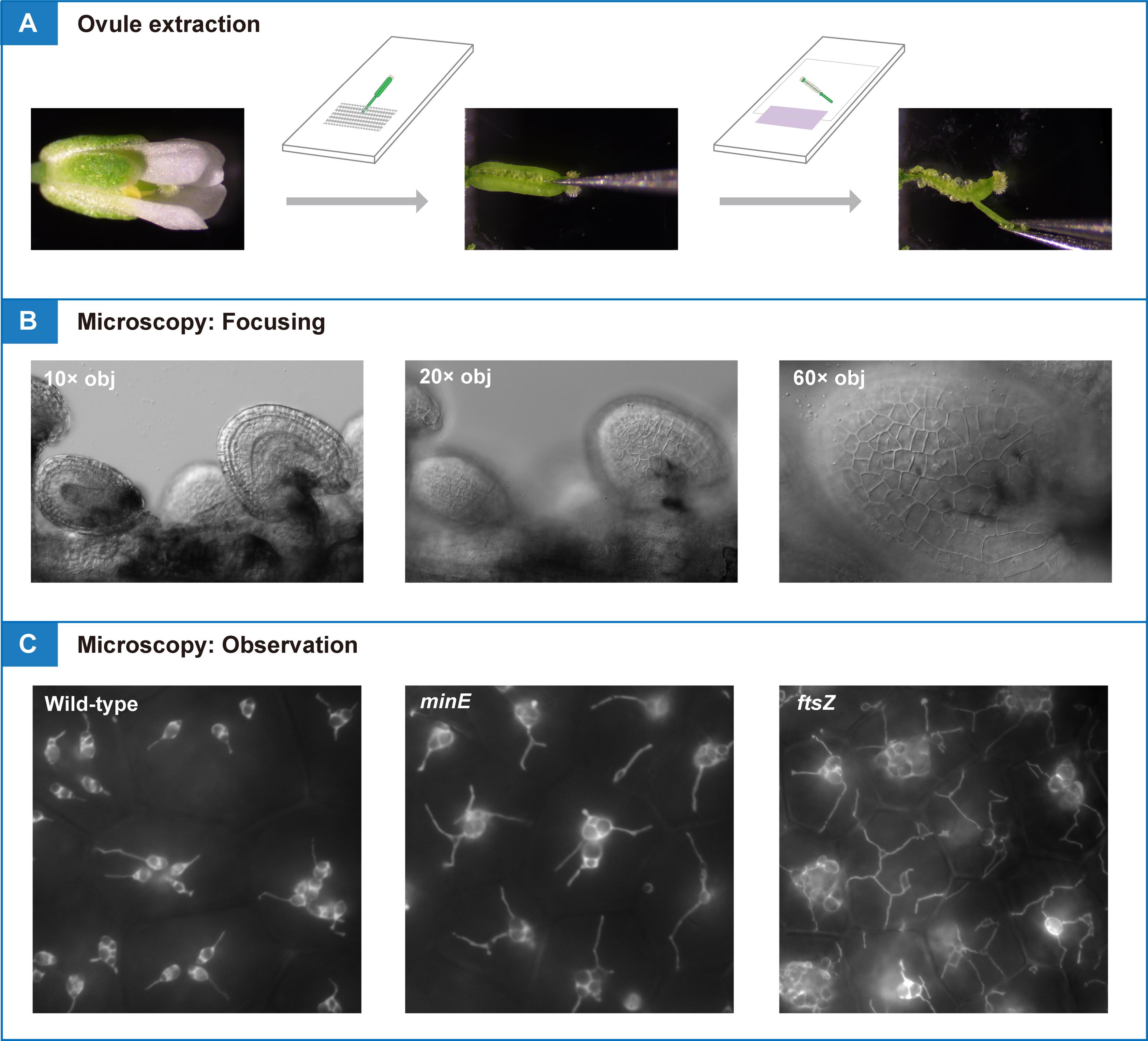
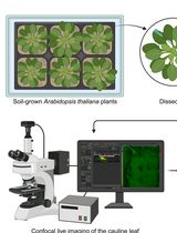
Pistils or siliques are dissected and subjected to conventional fluorescence microscopy for amyloplast observation and quantification in living tissue
Background
Plastids are double membrane–bound organelles found in the cells of seed plants that exhibit unique features of functional and morphological differentiation. These include chloroplasts in leaves, chromoplasts in flowers and fruits, and leucoplasts in general non-photosynthetic tissues [1]. Amyloplasts are non-photosynthetic plastids specialized for starch synthesis and storage. Amyloplasts develop from undifferentiated proplastids in meristematic tissues and are distributed in storage tissues such as roots, stems, and seeds, as well as in gravity-sensing tissues (for example, the stem endodermis and root cap columella) [2]. As starch is an important source of nutrients in human diets, the differentiation and proliferation of amyloplasts have long been an important area of crop biology research.
Plastids possess their DNA and typically replicate by binary fission [3,4]. In leaf mesophyll cells of the model plant Arabidopsis thaliana, chloroplast division is initiated by the formation of the stromal FtsZ ring and involves approximately 20 nuclear-encoded gene products located in the stroma, inner-envelope membrane, outer-envelope membrane, or cytoplasm [5,6]. In contrast, the mechanisms governing amyloplast proliferation remain largely unknown, partly due to the lack of an experimental system to track their number and behavior in specific cells.
We recently proposed that the Arabidopsis ovule integument could provide a platform for live-cell imaging of amyloplast replication and morphology, including the dynamics of stroma-filled tubules (stromules) [7]. This method may open a way to analyzing the function and regulation of plastid-division proteins during amyloplast proliferation in non-photosynthetic cells. In this protocol, we provide technical tips for conventional fluorescence microscopy of integument amyloplasts using wild-type (WT) and plastid-division mutants of Arabidopsis.
Materials and reagents
Biological materials
1. Seeds of transgenic Arabidopsis lines with stable expression of stroma-targeted fluorescent proteins (see General note 1). This protocol presents data from transgenic lines in the Col background [8] and minE [9], and ftsZ triple [10] (hereafter, ftsZ) mutants, in which a transit peptide (the N-terminal 90 aa of AtFtsZ1-1 [8])-fused YFP is driven by the constitutive CaMV35S promoter (see Figure 1)
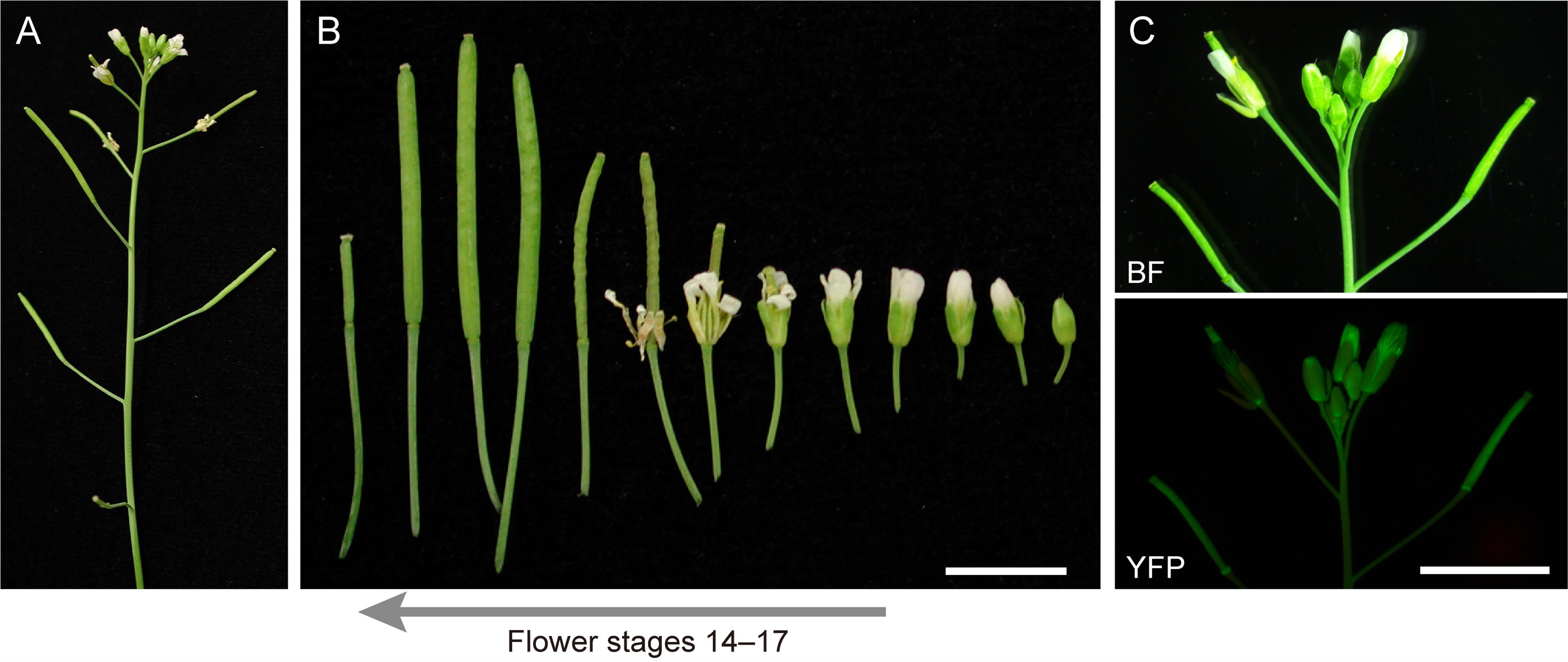
Figure 1. Reproductive stages of Arabidopsis suitable for analysis of amyloplast replication. (A) Primary inflorescence. (B) Flower stages 14–17 [11] used for ovule extraction. (C) Expression pattern of CaMV35S promoter-driven stroma-targeted YFP in a transgenic Arabidopsis line. Images of brightfield (BF) and yellow fluorescent protein (YFP) signals are shown. Scale bar, 5 mm.
Reagents
1. Murashige and Skoog plant salt mixture (Wako Pure Chemical Industries, catalog number: 392-00591)
2. Sucrose (Wako Pure Chemical Industries, catalog number: 196-00015)
3. MES (Nacalai Tesque, catalog number: 21623-26)
4. Phyto agar (Duchefa Biochemie, catalog number: P1003.1000)
5. Jiffy-7 peat pellets, 44 × 42 mm (Jiffy International)
Laboratory supplies
1. Slide glass (Matsunami Glass, catalog number: S-2215)
2. Cover glass, 24 × 32 No. 1, thickness 0.13–0.17 mm (Matsunami Glass, catalog number: C024321)
3. Micropore surgical tape (3M, catalog number: 1530SP-0)
4. Paper tape (As One, catalog number: 6-691-01)
Equipment
1. Stereomicroscope with 0.63× objective lens (Leica Microsystems, model: MZ10 F)
2. CCD camera (Olympus, model: DP26) with 0.63× adaptor, attached to Leica MZ10 F
3. Inverted fluorescence microscope with 10×, 20×, and 60× objective lenses (Olympus, model: IX71)
4. CMOS camera (Hamamatsu Photonics, model: ORCA-flash2.8) with a 1.0× adaptor, attached to Olympus IX71
5. Tweezers 1 (Fontax, No. 5 Taxal)
6. Tweezers 2 (Dumont, No. DU-55 Dumoxel)
Software and datasets
1. Imaging software CellSens (Olympus, controller for DP26 camera)
2. Imaging software HCImage (Hamamatsu Photonics, controller for ORCA-flash2.8 camera)
Procedure
A. Plant cultivation and extraction of ovules for microscopy
1. Sow seeds on Murashige and Skoog medium (pH 5.7) supplemented with 0.1% MES, 2% sucrose, and 0.7% agar (see General note 2). Treat the seeds in the dark at 4 °C for several days [9]. Germination occurs in one or several days after irradiation at 23 °C. After germination, transfer seedlings to Jiffy-7 peat pellets pre-soaked in water and grow under a 16/8 light/dark cycle of white light illumination at 23 °C for 5–6 weeks (see General note 2; Figure 1).
2. Prepare two glass slides. One (slide 1) is used for ovule extraction. The other (slide 2), together with 1–3 layers of colored tape as a spacer, is used for microscopy analysis (see General note 3).
3. Excise an intact flower or silique from an inflorescence stem of an adult plant (see General note 4).
4. Place the flower or silique (segment) on slide 1. Fix the organ in place using surgical tape by securing the pedicle at one point so that it does not move during dissection (Figure 2A–E).
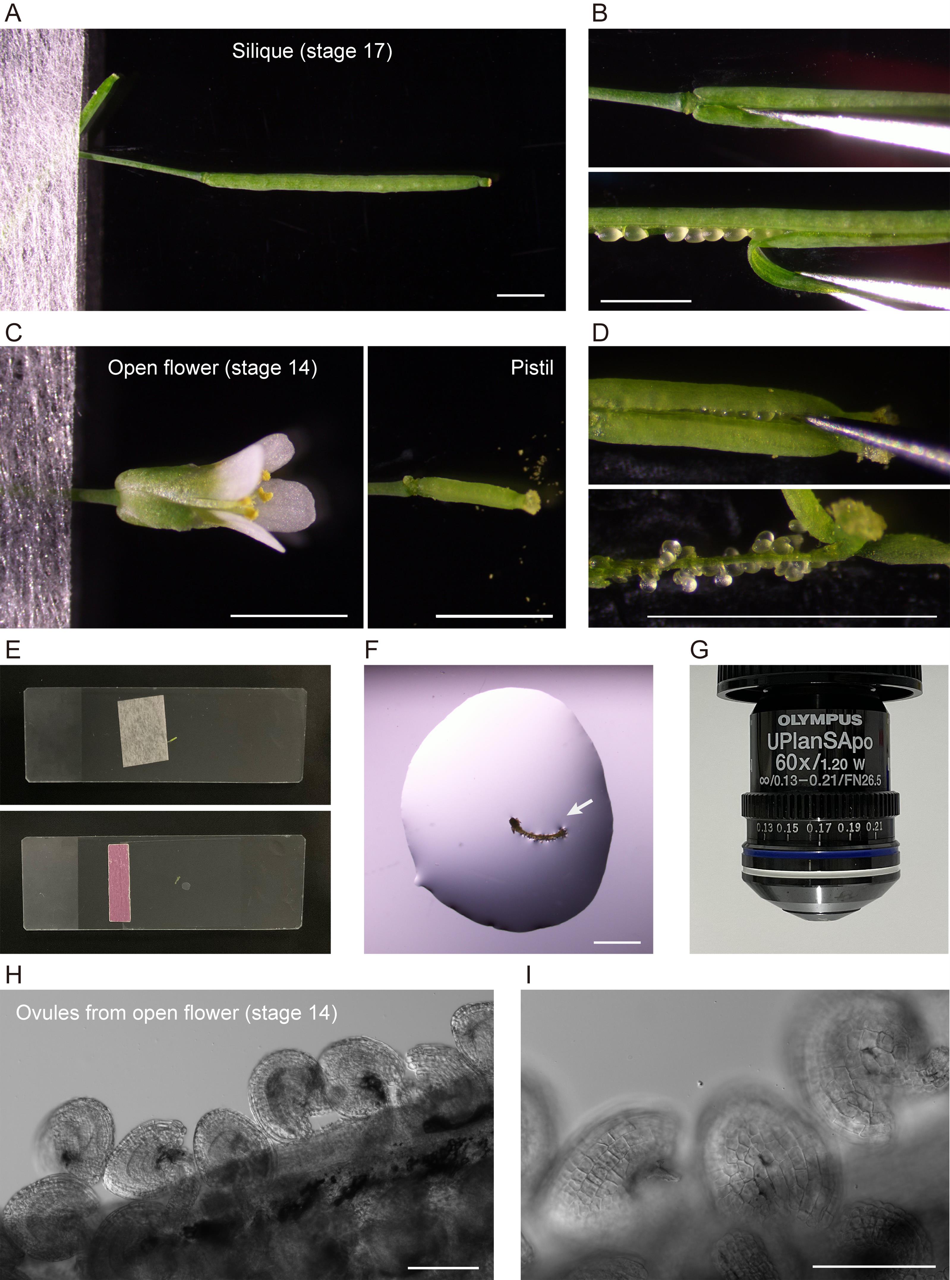
Figure 2. Extraction of ovules for microscopic analysis. (A,B) Sampling and dissection of a silique. (C,D) Sampling and dissection of a pistil from an open flower. (E) Slides used for dissection (top) and microscopy (bottom). (F) An extracted septum–ovule association (arrow) mounted in water. (G) 60× objective used for microscopy. (H, I) Ovules observed under 10× (H) and 20× (I) objectives. Scale bars, 2 mm (A–D, F) and 100 μm (H, I).
5. To extract ovules from a silique at flower stages 16–17, remove sepals, petals, and stamens from the silique, if attached, using basic tweezers (tweezers 1) under a stereomicroscope at zoom 2.0–3.2×. Peel off either or both valves (this is optional) from the silique (Figure 2A, B).
6. To extract ovules from a pistil at flower stages 13–16, remove sepals, petals, and stamens from an open flower using extra-fine tweezers (tweezers 2) under a stereomicroscope at zoom 6.3×. Peel off either or both valves (this is optional) from the pistil (Figure 2C, D).
7. Apply 40–70 µL of deionized water or liquid Murashige and Skoog medium onto slide 2. Transfer a septum–ovule association obtained by dissection to the water drop (Figure 2F).
8. Mount a coverslip carefully onto the slide (see General note 5). Gently apply the mounting medium between the coverslip and the slide, so that it just fills the space between them (Figure 2E).
9. Confirm the extraction of intact ovules by low-magnification light microscopy (Figure 2H, I).
10. Observe amyloplasts in outer ovule integument (epidermal or oi2 [12]) cells by high-magnification fluorescence microscopy using a 60×/1.20 NA water-immersion objective (Figure 2G; see section B).
B. Observation of amyloplasts by conventional fluorescence microscopy
1. Turn on the halogen lamp, mercury lamp, camera controller (computer), and digital camera.
2. Place slide 2 on the stage of the inverted fluorescence microscope.
3. To perform counting and morphological characterization of amyloplasts, use a 60× water-immersion objective (Figure 2G). Microscope settings for the detection of YFP are described in Table 1.
4. Start the camera controller software HCImage (Hamamatsu Photonics). The settings of the mercury lamp and camera for the detection of YFP fluorescence are described in Table 2.
5. Explore and focus on individual ovules at 60× through eyepieces using differential interference contrast (DIC) optics.
6. Perform image acquisition (Figures 3–5). For time-lapse fluorescence microscopy, we manually focus on individual cells and capture images for up to 60 min. Each image is captured every 30 s or 1 min.
Table 1. Settings for standard epifluorescence microscopy
| Item | Products/values (maker) |
|---|---|
| Objective | 10× dry (N.A. 0.40), 20× dry (N.A. 0.75) 60× water-immersion lens (N.A. 1.20) |
| Light source for DIC observation | Halogen lamp at 10%–50% output (TH4-100, Olympus) |
| Light source for fluorescence observation | Mercury lamp at 3%–12% output (U-HGLGPS, Olympus) Plus ND filter 25 |
| Optical filters for YFP | BP490-500HQ (ex) (Olympus) FF506-DiO3 (di) (Semrock) FF01-545/55 (em) (Semrock) |
Table 2. Settings of the camera and software for fluorescence detection
| Item | Products/values |
| Image | 12 bit, 1,920 × 1,440 pixel |
| Binning | 1 |
| HCImage software for single image capture: Gain (range: 0–255) Exposure | 100 500 ms |
| HCImage software for time-lapse microscopy: Gain (range: 0–255) Exposure | 150 500 ms |
Data analysis
A. Morphological characterization and counting of mature amyloplasts in WT
1. Single and compound starch granules in amyloplasts can be distinguished using both brightfield (DIC) and YFP fluorescence imaging (Figure 3A, WT). Stromal YFP does not enter the interior of starch grains but accumulates in a small space(s) between grains.
2. The amyloplast distribution from the top to the bottom of a tile-formed cell is checked using both DIC and stromal YFP, or by DIC imaging alone. The amyloplast number per cell is obtained with relative ease.
B. Morphological characterization and counting of mature amyloplasts in plastid-division mutants
1. The observation points essentially resemble those of WT amyloplasts, but the following observations are specific to plastid-division mutants. Integument cells of chloroplast division-inhibition mutants often contain YFP-labeled and starchless plastids. Such starchless plastids occur occasionally in WT but frequently appear in severe plastid-division inhibition mutants.
2. In general, an unusually elevated number of starch granules occurs inside giant amyloplasts.
3. Another structural factor in amyloplasts of plastid-division mutants is the activation of stromule formation in cells. Starch grains are often detected within stromules. In particular, ftsZ mutants tend to show extended stromule formation until late Phase III or early Phase IV amyloplasts. In such cases, a stromule-starch grain(s)-giant amyloplast association should be counted as a single amyloplast (Figure 3A, minE and ftsZ).
4. In ftsZ mutants, activated stromules disappear in late Phase III or early Phase IV (Figure 3B, C). Although amyloplast counting is more difficult at early Phase IV than at late Phase III, because of limited cytoplasmic space, the final amyloplast number per cell is revealed.
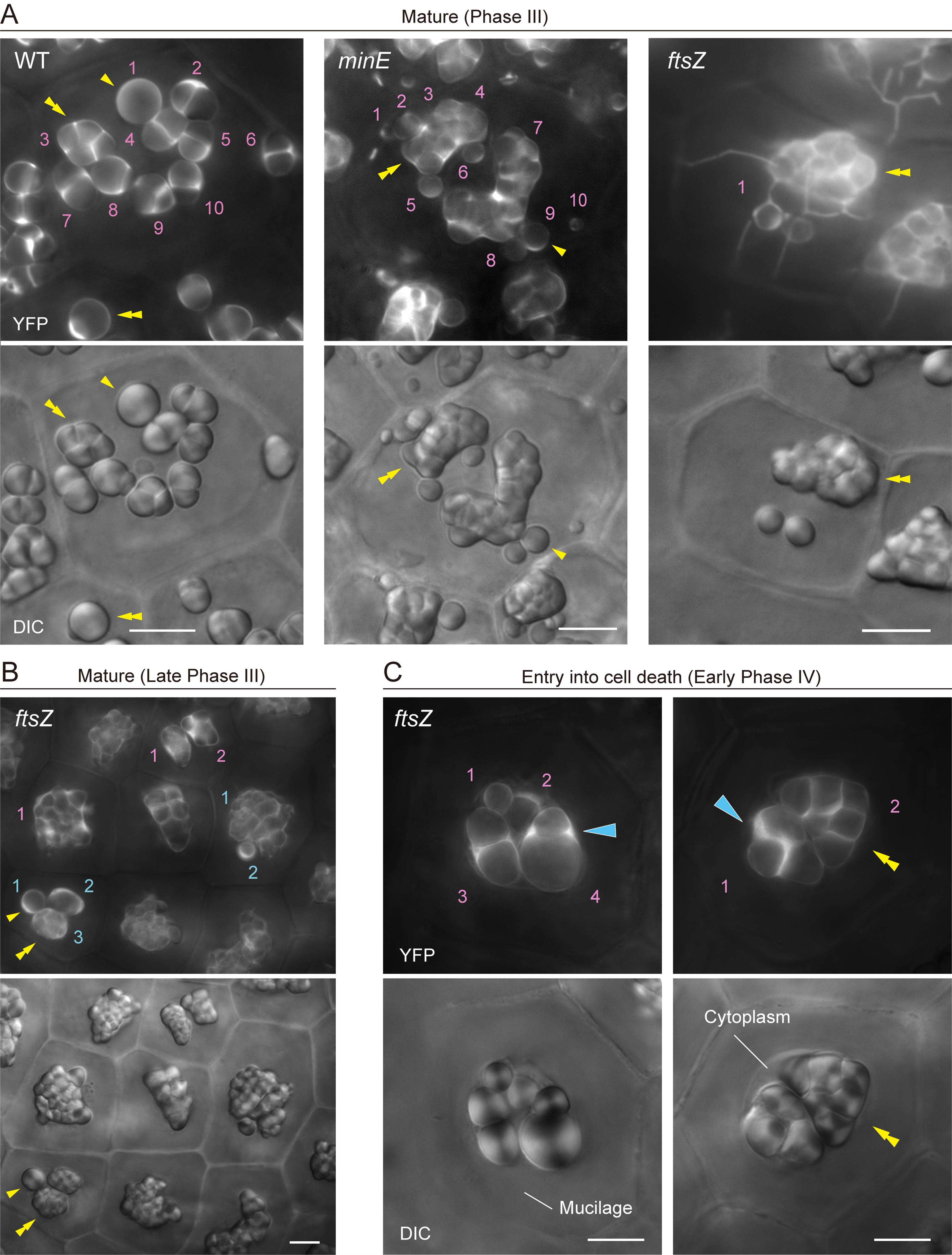
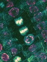
Figure 3. Amyloplast count and morphology in integument cells of wildtype (WT), minE, and ftsZ plants. (A) Integument cells of WT, minE, and ftsZ plants with developed amyloplasts (Phase III). (B) Integument cells of ftsZ with fully mature amyloplasts (late Phase III). (C) Integument cells of ftsZ upon entry into the cell death stage (early Phase IV). (A–C) show images of stroma-targeted YFP (top) and DIC (bottom). Single and double yellow arrowheads indicate single and compound starch grains, respectively. Cyan single arrowheads indicate the accumulation of stromal YFP in amyloplasts. Numbers indicate amyloplast counts per cell. Scale bars, 10 µm.
C. Morphological characterization and counting of amyloplasts during middle development in WT and plastid-division mutants
1. During the middle development of amyloplasts, the number as well as the starch grain morphology in each amyloplast from both WT and plastid-division mutants should be judged using both DIC and stromal YFP images. Amyloplast counting is difficult when using only DIC images (Figure 4, WT). The distribution patterns of stromal fluorescent proteins, the position and shape of starch grains, and their temporal change during the observation enable these characterizations.
2. If starch grain-containing stromules are not separated from the main body of amyloplasts, they are regarded as a single amyloplast (Figure 4, minE).
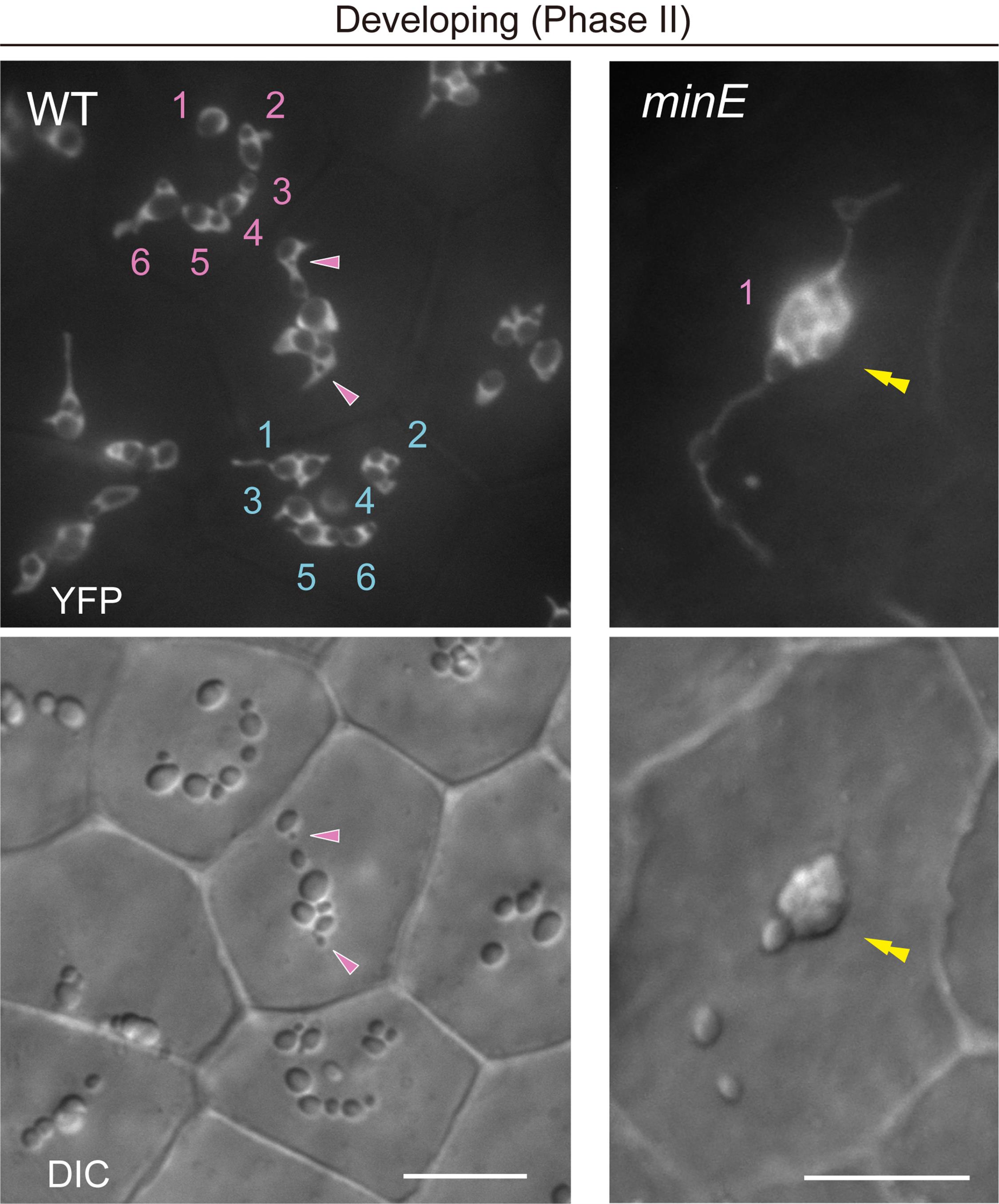
Figure 4. Count and morphology of middle-developed amyloplasts in wildtype (WT) and minE integument cells. Images show stroma-targeted yellow fluorescent protein (YFP) and differential interference contrast (DIC). Single and double arrowheads indicate the position of stroma-accumulated YFP signals and compound starch grains, respectively. Numbers indicate amyloplast counts per cell. Scale bars, 10 μm.
D. Morphological characterization and counting of proplastids or early differentiating amyloplasts in WT and plastid-division mutants
1. To assess amyloplast proliferation phenotypes during ovule development in WT and plastid-division mutants, information on the proplastid number per cell is critical. The following four factors are essential for this analysis:
a. A high level of stromal fluorescence signal for proplastid labeling.
b. Clear-cut fluorescence detection conditions to capture the proplastid configuration.
c. Counting by live observation, rather than by using static fluorescence images only.
d. Counts that recognize the entire proplastid configuration within a given cell by shifting the focus from the top to the bottom of the cell.
If one or more of the above factors are unsatisfactory, precise counting of proplastids may become difficult.
2. Selected captured images of proplastids in integument cells of WT (Figure 5A) and ftsZ (Figure 5B) are presented as examples. In WT, proplastids are often distributed at the top and bottom surfaces of integument cells and assume a dumbbell shape. In ftsZ, proplastids extend stromules in three dimensions. The extent of stromule elongation and branching is relatively modest in young cells compared with that in more mature and expanded cells. The small volumes of integument cells in mature ovules, prior to their development after fertilization [13,14], enable proplastid counting in ftsZ.
3. Counting and analysis of early differentiating (Phase I) amyloplasts are most difficult, as indicated in Figure 5C. Integument cells begin to expand, and differentiating amyloplasts also grow larger. In addition, individual amyloplasts are often hard to distinguish.
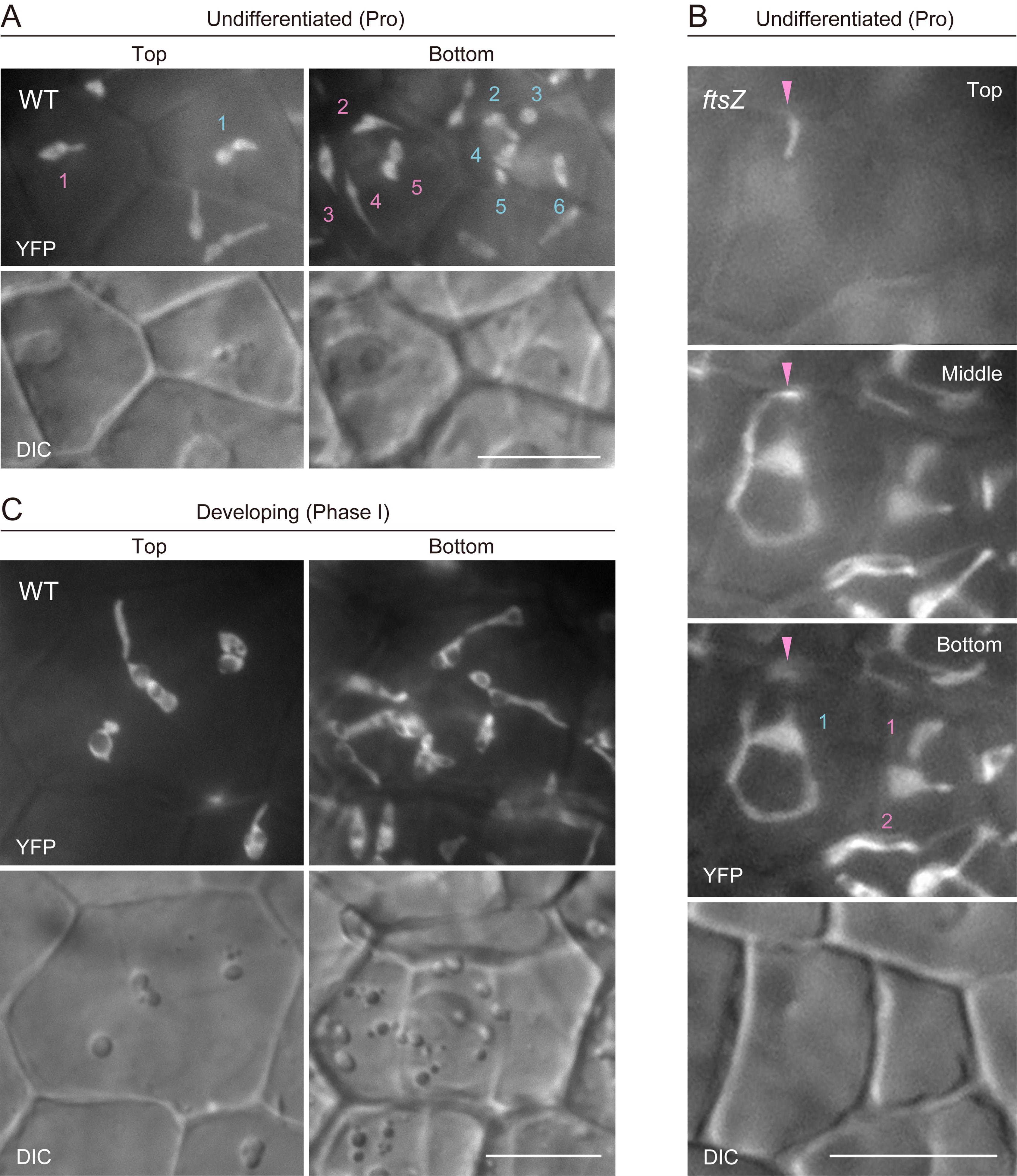
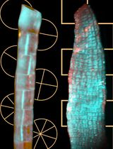
Figure 5. Count and morphology of proplastids and early differentiating (Phase I) amyloplasts in integument cells of wild-type and ftsZ plants. (A–C) Images of stroma-targeted yellow fluorescent protein (YFP) and differential interference contrast (DIC). Single arrowheads indicate the location of an extending stromule along the z-axis. Numbers indicate amyloplast counts per cell. Scale bars, 10 μm.
Validation of protocol
This protocol, or parts of it, has been used and validated in the following research article:
Fujiwara et al. [7]. Principles of amyloplast replication in the ovule integuments of Arabidopsis thaliana. Plant Physiology (Figure 1F–K, M–O; Figure 2A–D; Figure 4A–D; Figure 5A–E; and Supplementary figures).
General notes and troubleshooting
General notes
1. This system is compatible with commonly used fluorescent proteins, including GFP, CFP, YFP, and RFP.
2. Sowing seeds on 1%–3% sucrose-containing Murashige and Skoog media or directly into Jiffy-7 resulted in similar amyloplast development and proliferation results. We cultivated one plant per Jiffy-7. We do not recommend using >7-week-old plants for analysis.
3. Flower stages 13–14 [11] allow for the analysis of proplastids in integument cells. Flower stages 15–17 are suitable for examining developing or mature amyloplasts.
4. Selection of inflorescence stems: We primarily use primary to third inflorescence stems for analysis.
5. Take special care when extracting ovules and mounting samples and coverslips.
Acknowledgments
We thank Prof. Katherine W. Osteryoung (Michigan State University) for providing seeds of the ftsZ triple mutant, INRA (France) for seeds of minE, and Dr. Hiroaki Ichikawa (NIAS) for the original T-DNA vector. We also thank Mr. Ichiro Hamano for supporting the microscope setting. This study was supported by Grants-in-Aid for scientific research from the Ministry of Education, Culture, Sports, Science and Technology, Japan (26440152 to R.D.I.) and by grants from Sophia University (to M.T.F.). Contributions for each author: Conceptualization, M.T.F.; Investigation, M.T.F., R.A. Writing—Original Draft, M.T.F., R.A.; Writing—Review & Editing, M.T.F., T.A., R.D.I.
Competing interests
The authors declare no conflicts of interest.
References
- Kirk, J.T.O. and Tilney-Bassett, R. A. E. (1978). The plastids: their chemistry, structure, growth and inheritance. 2nd Ed. Elsevier/North- Holland Biomedical Press, Amsterdam.
- Pyke, K. A. (2009). Plastid biology. Cambridge University Press, Cambridge. https://doi.org/10.1093/aob/mcq100
- Possingham, J. and Lawrence, M. (1983). Controls to Plastid Division. Int Rev Cytol. 84: 1–56. https://doi.org/10.1016/s0074-7696(08)61014-1
- Leech, R. M. and Pyke, K. A. (1988). Chloroplast division in higher plants with particular reference to wheat. In Boffey SA, Lloyd D (Eds). Division and Segregation of Organelles. Cambridge University Press, 39–62.
- Osteryoung, K. W. and Pyke, K. A. (2014). Division and Dynamic Morphology of Plastids. Annu Rev Plant Biol. 65(1): 443–472. https://doi.org/10.1146/annurev-arplant-050213-035748
- Chen, C., MacCready, J. S., Ducat, D. C. and Osteryoung, K. W. (2017). The Molecular Machinery of Chloroplast Division. Plant Physiol. 176(1): 138–151. https://doi.org/10.1104/pp.17.01272
- Fujiwara, M. T., Yoshioka, Y., Kazama, Y., Hirano, T., Niwa, Y., Moriyama, T., Sato, N., Abe, T., Yoshida, S., Itoh, R. D., et al. (2024). Principles of amyloplast replication in the ovule integuments of Arabidopsis thaliana. Plant Physiol. 196(1): 137–152. https://doi.org/10.1093/plphys/kiae314
- Chen, Y., Asano, T., Fujiwara, M. T., Yoshida, S., Machida, Y. and Yoshioka, Y. (2009). Plant Cells Without Detectable Plastids are Generated in the crumpled leaf Mutant of Arabidopsis thaliana. Plant Cell Physiol. 50(5): 956–969. https://doi.org/10.1093/pcp/pcp047
- Fujiwara, M. T., Hashimoto, H., Kazama, Y., Abe, T., Yoshida, S., Sato, N. and Itoh, R. D. (2008). The Assembly of the FtsZ Ring at the Mid-Chloroplast Division Site Depends on a Balance Between the Activities of AtMinE1 and ARC11/AtMinD1. Plant Cell Physiol. 49(3): 345–361. https://doi.org/10.1093/pcp/pcn012
- Schmitz, A. J., Glynn, J. M., Olson, B. J., Stokes, K. D. and Osteryoung, K. W. (2009). Arabidopsis FtsZ2-1 and FtsZ2-2 Are Functionally Redundant, But FtsZ-Based Plastid Division Is Not Essential for Chloroplast Partitioning or Plant Growth and Development. Mol Plant. 2(6): 1211–1222. https://doi.org/10.1093/mp/ssp077
- Smyth, D. R., Bowman, J. L. and Meyerowitz, E. M. (1990). Early flower development in Arabidopsis. Plant Cell. 2(8): 755–767. https://doi.org/10.1105/tpc.2.8.755
- Vijayan, A., Tofanelli, R., Strauss, S., Cerrone, L., Wolny, A., Strohmeier, J., Kreshuk, A., Hamprecht, F. A., Smith, R. S. and Schneitz, K. (2021). A digital 3D reference atlas reveals cellular growth patterns shaping the Arabidopsis ovule. eLife 10: e63262. https://doi.org/10.7554/eLife.63262
- Windsor, J. B., Symonds, V. V., Mendenhall, J. and Lloyd, A. M. (2000). Arabidopsis seed coat development: morphological differentiation of the outer integument. Plant J. 22(6): 483–493. https://doi.org/10.1046/j.1365-313x.2000.00756.x
- Western, T. L., Skinner, D. J. and Haughn, G. W. (2000). Differentiation of Mucilage Secretory Cells of the Arabidopsis Seed Coat. Plant Physiol. 122(2): 345–356. https://doi.org/10.1104/pp.122.2.345
Article Information
Publication history
Received: Jan 29, 2025
Accepted: May 6, 2025
Available online: May 22, 2025
Published: Jun 5, 2025
Copyright
© 2025 The Author(s); This is an open access article under the CC BY license (https://creativecommons.org/licenses/by/4.0/).
How to cite
Readers should cite both the Bio-protocol article and the original research article where this protocol was used:
- Fujiwara, M. T., Arakawa, R., Abe, T. and Itoh, R. D. (2025). Using a Live Analysis System to Study Amyloplast Replication in Arabidopsis Ovule Integuments. Bio-protocol 15(11): e5333. DOI: 10.21769/BioProtoc.5333.
- Fujiwara, M. T., Yoshioka, Y., Kazama, Y., Hirano, T., Niwa, Y., Moriyama, T., Sato, N., Abe, T., Yoshida, S., Itoh, R. D., et al. (2024). Principles of amyloplast replication in the ovule integuments of Arabidopsis thaliana. Plant Physiol. 196(1): 137–152. https://doi.org/10.1093/plphys/kiae314
Category
Plant Science > Plant cell biology > Cell imaging
Cell Biology > Cell imaging > Live-cell imaging
Do you have any questions about this protocol?
Post your question to gather feedback from the community. We will also invite the authors of this article to respond.