- Protocols

- Articles and Issues
- For Authors
- About
- Become a Reviewer

Development of Polyethylene Glycol Diacrylate-Based Micropattern Substrate to Study the Interplay Between Surface Topography and Cellular Response for Tissue Engineering Applications

Published: Vol 15, Iss 10, May 20, 2025 DOI: 10.21769/BioProtoc.5323 Views: 2810
Reviewed by: Rajesh RanjanEVANGELOS THEODOROUAnonymous reviewer(s)
Original research article
The authors used this protocol in:

Sep 2022
Advertisement


Protocol Collections
Comprehensive collections of detailed, peer-reviewed protocols focusing on specific topics


Related protocols
Abstract
A key goal in the bioengineering field is the development of surface patterning of proteins that guide and control cellular organization. To this end, we developed a method to create a microstructured hydrogel based on soft-lithography techniques using polydimethylsiloxane (PDMS) and polyethylene glycol diacrylate (PEGDA). This approach involves the design of microfluidic geometries using graphical software, employing PDMS as a mold and leaving PEGDA as a substrate for the fabrication of microstructures and, thus, patterning extracellular matrix (ECM) proteins to promote cell adhesion. The combination of these techniques allows the fabrication of hydrogel microstructures without following conventional photolithography methods, such as the use of a photomask, the alignment required to produce the patterns, and the associated expenses. This study highlights the versatility and potential of PEGDA-based hydrogels as platforms to advance tissue engineering strategies.
Key features
• This protocol focuses on investigating the feasibility of patterning PEGDA as a substrate for protein surface patterning and further tissue engineering applications.
• Optimization of the fabrication of PEGDA hydrogels into simple shapes and angular patterns, ensuring a robust substrate capable of guiding cellular responses.
Keywords: PEGDAGraphical overview
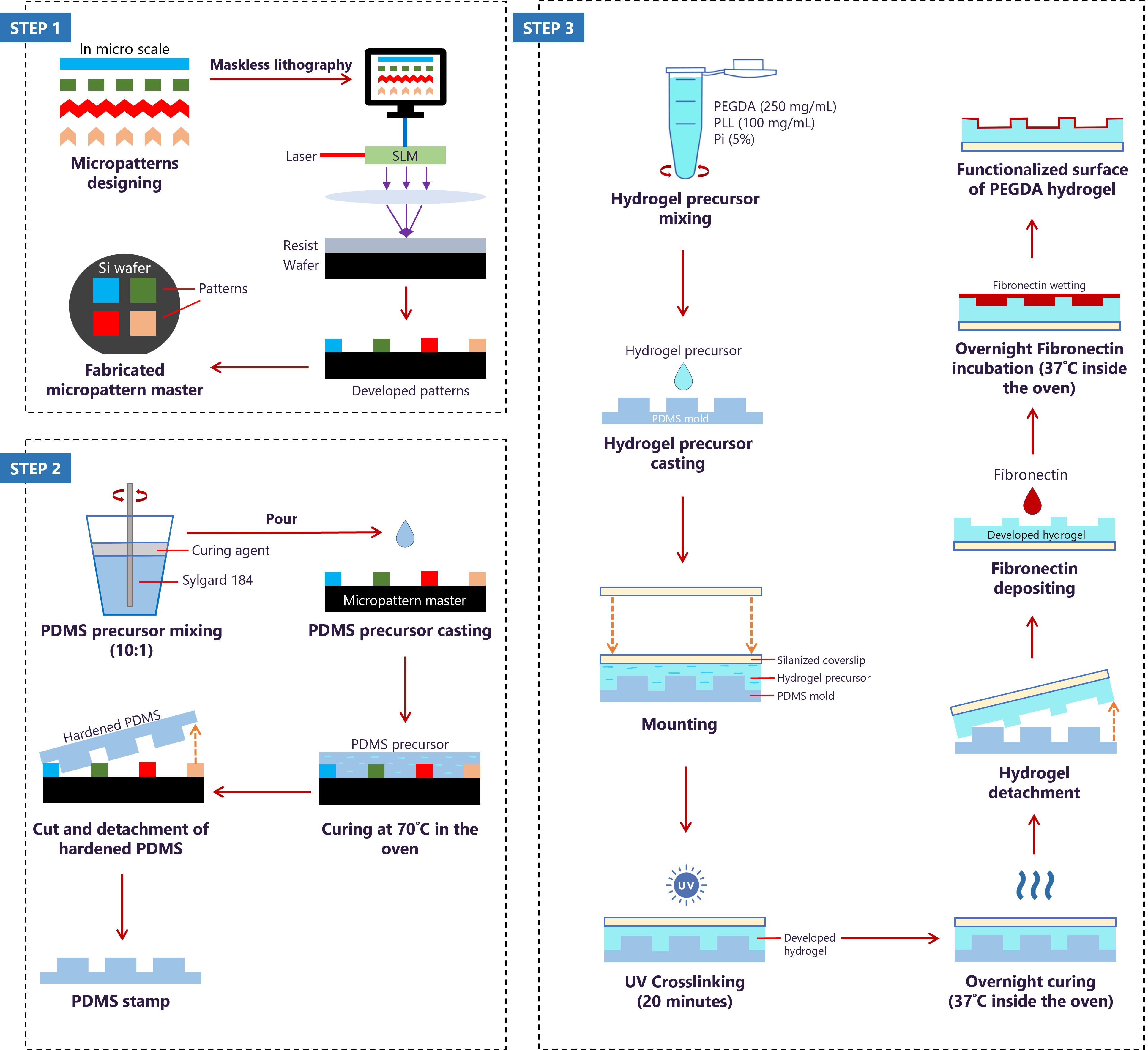
Fabrication of biofunctionalized microtopography hydrogels using soft lithography and fibronectin-deposition approach. The protocol consists of designing micropatterns for the fabrication of the silicon (Si) wafer using QCAD graphical software (step 1), followed by mixing and casting the PDMS precursor on the Si wafer to obtain PDMS molds with the different micropatterns (step 2). Finally, developing PEGDA hydrogel on the PDMS mold to transfer micropatterns to the hydrogel and depositing fibronectin on the hydrogel’s surface to functionalize it (step 3).
Background
Central to the new era of tissue engineering is the development of biofunctionalized scaffolds where engineered structures are designed to mimic the intricate extracellular matrix (ECM) and support cellular growth [1–4]. Collaborative efforts by material scientists, electronic engineers, and cell biologists have led to cutting-edge techniques, such as microfabrication and nanotechnology, to create scaffolds that can closely imitate the native ECM to guide cell behaviour [1–6]. Although the interconnected roles of biochemical and biophysical cues are widely recognized [7–9], researchers often focus on biochemical aspects, overlooking the importance of biophysical cues in guiding cell behaviour. Hydrogel substrates have been created through pattern transfer using deep UV lithography and/or soft lithography, with a focus on fabricating polyethylene glycol diacrylate (PEGDA)-based hydrogels. Polyethylene glycol (PEG), being inherently inert to protein adsorption and cellular attachment, is considered ideal for anti-fouling coatings in biomedical applications and medical devices [17,18]. Linear PEG can be chemically modified into a reactive polymeric mesh network with a diacrylate (DA) crosslinker [10], making PEGDA suitable for various applications, such as drug delivery systems, tissue engineering, and wound healing [11–15]. The utility of PEGDA lies in its tunability of its mechanical and physico-chemical properties [10,16,17]. This versatility allows for precise control over the PEGDA’s characteristics, such as shape, stiffness, swelling behaviour, and degradation rate, making it an excellent choice for creating customized materials, including specific patterns and topographies [10,16,17]. However, since PEGDA remains inert to cell attachment, the coating of fibronectin, homogeneously or in selective PEGDA regions, enhances its bio-functionality and promotes cell adhesion on the PEGDA surface. Overall, the feasibility of creating and using patterned PEGDA allows for the optimization of surface properties to guide cellular organization, advancing its applications in tissue engineering.
Materials and reagents
Biological materials
1. C2C12 cell line (ATCC, catalog number: CRL-1772)
2. Fetal bovine serum (FBS) (Sigma Life Science, catalog number: F7524)
3. Fibronectin (Sigma-Aldrich, catalog number: F1141)
4. Fibrinogen (Thermo Fisher Scientific, catalog number: F35200)
Reagents
1. Dulbecco’s modified Eagle medium (DMEM) supplemented with 4.5 g/L D-glucose, L-glutamine, and pyruvate (Gibco, catalog number: 41966-029)
2. Penicillin/Streptomycin (Thermo Fisher Scientific, catalog number: 15140122)
3. Trypsin-EDTA (0.25%), phenol red (Thermo Fisher Scientific, catalog number: 25200072)
4. 1× phosphate saline buffer (PBS) (Thermo Fisher Scientific, catalog number: 14190169)
5. Trypan blue (Invitrogen, catalog number: T10282)
6. Alamar blue (Thermo Fisher Scientific, catalog number: DAL1025)
7. Absolute ethanol (Carl Roth, catalog number: 9065.5)
8. Acetic acid (Honeywell, catalog number: 607-002-00-6)
9. 3-(Trimethoxysily) propyl methacrylate (Silane A174) (Sigma-Aldrich, catalog number: 440159)
10. Polyethylene glycol diacrylate (PEGDA) (MW = 700) (Sigma-Aldrich, catalog number: 455008)
11. Poly(L-lysine) (PLL) (Biosynth, catalog number: FP14985)
12. PLPP gel photoinitiator (Alvéole)
13. 70% ethanol
14. Isopropanol
15. Acetone
16. Sylgard 184 elastomer base and curing agent (VWR, catalog number: 634165S)
17. 4% paraformaldehyde (PFA)
18. Phalloidin-TRITC (Sigma-Aldrich, catalog number: P1951)
19. Hoechst (Thermo Fisher Scientific, catalog number: H1398)
20. Mowiol (Carl Roth, catalog number: 0731.2)
21. Sodium hydroxide solution (NaOH) (lab-made)
22. Ultrapure water (lab-made)
23. Bovine serum albumin (BSA) powder (Sigma-Aldrich, catalog number: A2153)
24. 4-(2-hydroxyethyl)-1-piperazineethanesulfonic acid (HEPES) (Sigma-Aldrich, catalog number: C-40020)
Solutions
1. Complete cell culture medium (see Recipes)
2. Sodium hydroxide solution (see Recipes)
3. PLL mix solution (see Recipes)
4. PEGDA mix solution (150 mg/mL) (see Recipes)
5. PEGDA mix solution (250 mg/mL) (see Recipes)
6. PEGDA mix solution (350 mg/mL) (see Recipes)
7. Hydrogel precursor solution (see Recipes)
8. Alamar blue solution (see Recipes)
9. Silanization immersion solution (see Recipes)
10. HEPES solution (see Recipes)
11. Micropattern labeling solution (see Recipes)
12. 5% BSA solution (see Recipes)
13. 1% BSA solution (see Recipes)
14. PDMS solution (see Recipes)
15. Immunostaining solution (see Recipes)
Recipes
1. Complete cell culture medium (50 mL)
Storage: 4 °C, up to 3 months.
| Reagent | Final concentration | Quantity or Volume |
|---|---|---|
| DMEM | n/a | 44.5 mL |
| FBS | 10% (v/v) | 5 mL |
| Penicillin/streptomycin | 1% (v/v) | 0.5 mL |
| Total | n/a | 50 mL |
2. Sodium hydroxide solution (100 mL, 0.15 M, pH 7.8)
Storage: room temperature, up to 6 months.
| Reagent | Final concentration | Quantity or Volume |
|---|---|---|
| NaOH solution (1 M) | 0.15 M | 15 mL |
| Ultrapure water | n/a | 85 mL |
| Total | n/a | 100 mL |
3. PLL mix solution (100 mg/mL)
Immediate use.
| Reagent | Final concentration | Quantity or Volume |
|---|---|---|
| PLL powder | 100 mg/mL (w/v) | 100 mg |
| NaOH solution (0.15 M) | n/a | 1 mL |
| Total | n/a | 1 mL |
4. PEGDA mix solution (150 mg/mL)
Immediate use.
| Reagent | Final concentration | Quantity or Volume |
|---|---|---|
| PEGDA solution (1 M) | 150 mg/mL (v/v) | 26.8 μL |
| Ultrapure water | n/a | 173.2 μL |
| Total | n/a | 200 μL |
5. PEGDA mix solution (250 mg/mL)
Immediate use.
| Reagent | Final concentration | Quantity or Volume |
|---|---|---|
| PEGDA solution (1 M) | 250 mg/mL (v/v) | 44.6 μL |
| Ultrapure water | n/a | 155.4 μL |
| Total | n/a | 200 μL |
6. PEGDA solution (350 mg/mL)
Immediate use.
| Reagent | Final concentration | Quantity or Volume |
|---|---|---|
| PEGDA solution (1 M) | 350 mg/mL (v/v) | 62.5 μL |
| Ultrapure water | n/a | 137.5 μL |
| Total | n/a | 200 μL |
7. Hydrogel precursor solution (0.42 mL)
Immediate use.
| Reagent | Final concentration | Quantity or Volume |
|---|---|---|
| PEGDA mix solution | 150/250/350 mg/mL (v/v) | 200 μL |
| PLL mix solution | 100 mg/mL (w/v) | 200 μL |
| PLPP gel photoinitiator | 5% | 20 μL |
| Total | n/a | 420 μL |
8. Alamar blue solution (100 μL)
Immediate use.
| Reagent | Final concentration | Quantity or Volume |
|---|---|---|
| Alamar blue | 10% | 10 μL |
| Complete culture medium | n/a | 90 μL |
| Total | n/a | 100 μL |
9. Silanization immersion solution (300 mL)
Immediate use.
| Reagent | Final concentration | Quantity or Volume |
|---|---|---|
| Ultrapure water | n/a | 10 mL |
| Acetic acid | 1 (ratio) | 18.75 mL |
| Silane A174 | 1 (ratio) | 18.75 mL |
| Absolute ethanol | 14 (ratio) | 252.5 |
| Total | n/a | 300 mL |
10. HEPES solution (500 mL)
Storage: 4 °C, up to 3 months.
| Reagent | Final concentration | Quantity or Volume |
|---|---|---|
| HEPES (1 M) | 10 mM | 5 mL |
| Ultrapure water | n/a | 495 mL |
| Total | n/a | 500 mL |
11. Micropattern labeling solution (0.7 mL)
Immediate use.
| Reagent | Final concentration | Quantity or Volume |
|---|---|---|
| Fibronectin | 50 μg/mL | 17.5 μL |
| Fibrinogen | 10 μg/mL | 4.7 μL |
| HEPES solution (10 mM) | n/a | 677.8 μL |
| Total | n/a | 700 μL |
12. 5% BSA solution (50 mL)
Storage: 4 °C, one week.
| Reagent | Final concentration | Quantity or Volume |
|---|---|---|
| BSA powder | 5% (w/v) | 2.5 g |
| 1× PBS | n/a | 50 mL |
| Total | n/a | 50 mL |
13. 1% BSA solution (50 mL)
Storage: 4 ˚C, one week.
| Reagent | Final concentration | Quantity or Volume |
|---|---|---|
| BSA powder | 1% (w/v) | 0.5 g |
| 1× PBS | n/a | 50 mL |
| Total | n/a | 50 mL |
14. PDMS solution (50 mL)
Storage: -20 ˚C, up to 5 months.
| Reagent | Final concentration | Quantity or Volume |
|---|---|---|
| Sylgard 184 elastomer base | 10 (ratio) | 50 g |
| Curing agent | 1 (ratio) | 5 g |
| Total | n/a | 55 g |
15. Immunostaining solution (0.7 mL)
Immediate use.
| Reagent | Final concentration | Quantity or Volume |
|---|---|---|
| Phalloidin | 1:200 | 3.5 μL |
| Hoechst | 1:1,000 | 0.7 μL |
| 5% BSA | n/a | 695.8 μL |
| Total | n/a | 700 μL |
Laboratory supplies
1. T-75 cell culture flask (Fisher Scientific, catalog number: 50-809-260)
2. Glass bottom 6-well plate (lab custom-made)
3. 96-well plate (Fisher Scientific, catalog number: 92096)
4. 6-well plate (Fisher Scientific, catalog number: 92006)
5. Hemocytometer (Sigma-Aldrich, catalog number: Z359629-1EA)
6. 20 × 20 mm2 glass coverslip (Carl Roth, catalog number: H873.2)
7. 18 × 18 mm2 glass coverslip (Carl Roth, catalog number: 0657.2)
8. Teflon rack (custom-made)
9. Glass box (custom-made)
10. 20 mL syringe (B. Braun Inkjet, catalog number: 4606736V)
11. 50 mm length needle (B. Braun Sterican, catalog number: 466 5503)
12. 1.5 mL microcentrifuge tubes (Axygen, catalog number: 10620934)
13. 0.6 mL microcentrifuge tubes (Nest Biotechnology, catalog number: 605001)
14. 15 mL conical tube (Fisher Scientific, catalog number: 20160618-058)
15. 50 mL conical tube (Cellstar, catalog number: 227261)
16. 5 mL serological pipette (Eppendorf, catalog number: 0030127714)
17. 10 mL serological pipette (Eppendorf, catalog number: 0030127722)
18. 25 mL serological pipette (Eppendorf, catalog number: 0030127730)
19. Aluminum foil (Reynolds Consumer Products LLC, catalog number: 1090000084)
20. Chromium mask (Toppan Photomasks, Inc.)
21. Micropattern master (IMSEAM, Heidelberg)
22. 100 mm diameter Petri dish (Corning, catalog number: 430167)
23. 60 mm diameter Petri dish (Falcon, catalog number: 353004)
24. 35 mm diameter Petri dish (Falcon, catalog number: 353001)
25. Spatula
26. Scalpel No. 11 (Fisher Scientific, catalog number: 11708353)
27. 76 mm × 26 mm microscope slides (Marienfeld, catalog number: 1000200)
Equipment
1. Incubator (Thermo Scientific, model: BBD 6220)
2. Automation cell Countess II FL (Invitrogen, model: AMQAF1000)
3. Multi-mode microplate reader (Tecan, model: Spark)
4. Nitrogen gun (MPI)
5. UV crosslinker chamber (Vilber Lourmat, model: BLX312)
6. Ultraviolet-ozone cleaner machine (Jetlight Company Inc., model: 342-220)
7. Vortex machine (StarLab, model: N2400-6110)
8. Fume hood (Thermo Fisher Scientific, model: EN 12469)
9. Weighing balance (Kern, model: AEJ 200-5CM)
10. Centrifuge machine (VWR, model: Mega Star 600R)
11. Desiccator (Duran, model: DN150)
12. -20 ˚C blast freezer (Liebherr, model: MediLine)
13. Oven (VWR, model: INCU Line)
14. Optical microscope (Zeiss, model: Primovert)
15. Optics11 Chiaro Nanoindeter (Optics11 Life)
16. Delta Vision (Olympus)
Software and datasets
1. QCAD software (3.31.1, 19.04.2024)
2. ImageJ software (1.8.0, 07.06.2024)
3. GraphPad Prism (8.4.3, 02.09.2024)
4. Optics11 Life DataViewer (V2, 31.07.2024)
Procedure
A. Cell culture maintenance
1. C2C12 cells are cultured in DMEM with 4.5 g/L D-glucose, L-glutamine, and pyruvate, 10% FBS, and 1% penicillin/streptomycin.
2. Maintain cells in subculture every 3 days at 75%–80% confluence.
3. Wash cells with 5 mL of PBS before trypsinization.
4. For cell detachment, add 1.5 mL of 0.25% (v/v) trypsin-EDTA to cells in a T-75 flask and incubate for 6 min inside the incubator. Then, add 3.5 mL of complete cell culture medium (see Recipe 1) to stop the trypsinization process.
5. Multiple gentle aspirations against the surface of the flask mechanically assist in the complete detachment of the cells.
6. For subculture, plate the cells into the media using a 1:10 ratio.
B. Surface silanization
Note: Surface silanization is necessary to ensure that the PEGDA hydrogel adheres to the coverslip, which simplifies the hydrogel development process and maintains its integrity on the coverslip.
Caution: This process must be carried out entirely inside a fume hood.
1. Dry each glass coverslip (20 mm × 20 mm) with a nitrogen flow to remove dust and place them inside a custom-made Teflon rack that fits the size of the coverslips.
2. Surface silanization uses a mixture of absolute ethanol, acetic acid, and Silane A174 in a volumetric ratio of 14:1:1, respectively.
Caution: Silane A174 is air sensitive. Make sure to add argon gas into the bottle immediately after use to maintain an inert condition.
3. Prepare the silanization immersion solution (see Recipe 9) to a final volume of 300 mL by first adding 10 mL of ultrapure water into the 300 mL measuring cylinder.
4. Next, pipette 18.75 mL of acetic acid into the graduated cylinder. Using a syringe, take 18.75 mL of silane A174 and add to the mixture.
5. Gently mix before adding absolute ethanol until reaching 300 mL.
6. Place the Teflon rack containing the coverslips inside a glass container and carefully pour in the silanization immersion solution.
7. Leave the coverslips inside the silanization immersion solution for at least 30 min.
8. After 30 min, rinse each coverslip with ethanol by slowly dipping it for 30 s. Then, dry the coverslips using nitrogen flow and store them inside a Petri dish until further use for the hydrogel platform.
Note: It is recommended that silanized coverslips be used within one week of preparation and sealed with parafilm while stored.
C. PEGDA hydrogel preparation
1. The preparation of hydrogel involves three different concentrations of PEGDA mix solution.
2. For each concentration, prepare two separate microcentrifuge tubes to accommodate the PEGDA solution and the PLL solution. Here, the concentration of the PLL mix solution is constant, which is 100 mg/mL.
3. The preparation of all concentrations of PEGDA mix solution is similar; the only difference is the volume measurement of PEGDA solution and water content. The details of volume measurements can be found in Recipes 4–6.
4. In the first tube, prepare 100 mg/mL of PLL mix solution by mixing 100 mg of PLL powder and 1 mL of 0.15 M NaOH solution. Vortex the mixture well until there is no clumpy powder.
5. Next, mix PEGDA (MW 700) solution with ultrapure water in another tube and mix the mixture well using a vortex.
6. Aliquot 200 μL of PEGDA mix solution and 200 μL of PLL mix solution into a new tube and vortex it well.
7. To make the hydrogel precursor solution, pipette 20 μL of PLPP gel photoinitiator into the tube of PEGDA-PLL mixture solution and vortex it well.
8. The PEGDA hydrogel precursor is ready to be used for cell seeding and PDMS micropatterning.
D. Cell seeding
1. Before seeding the cells, develop PEGDA hydrogel on the silanized coverslips (20 mm × 20 mm).
2. Perform cell seeding using a custom-made 6-well plate (glass bottom plate) (Figure 1). For the Alamar blue assay, a standard 96-well plate is used.
Note: Cellvis 6 micro-well glass bottom plate with #1.5 cover glass can be used as an alternative to the custom-made 6-well plate that is used in this protocol.
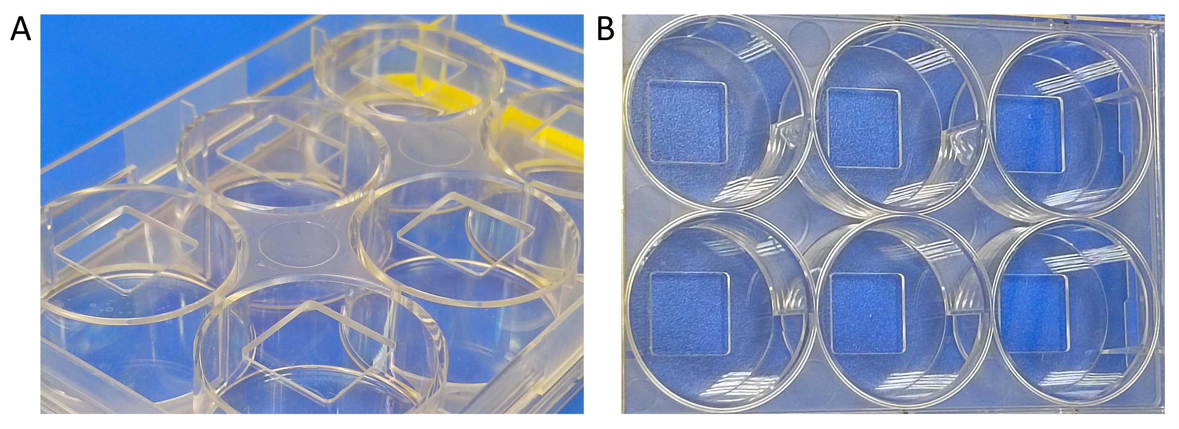
Figure 1. Custom-made 6-well plate used for cell seeding. (A) Bottom view of the well plate, which has spaces cut out for gluing coverslips. (B) Top view of the well plate.
3. Glue each silanized coverslip of adhered PEGDA hydrogel to the bottom of the custom-made 6-well plate, with the hydrogel facing up.
4. Mix the cell suspension with the trypan blue solution in a 1:1 ratio and pipette into hemocytometer channels.
5. Read the cell concentration using an automatic cell counter and seed the cells at a concentration of 1 × 10³ cells for both the PDMS approach and the Alamar blue assay.
6. For surface experimentation, allow cells to adhere for 15 min before adding the remaining volume of fresh medium into each well. After seeding, place the well plate into the incubator for 24 h under standard growth conditions.
E. Cell viability and proliferation assay
1. The Alamar blue (AB) assay is performed to assess cell viability and proliferation over three days in PEGDA hydrogel. Three different concentrations of PEGDA are tested: 150, 250, and 350 mg/mL (v/v). Meanwhile, the concentration of PLL to be used remains constant at 100 mg/mL (w/v) (see Recipe 3).
2. First, prepare PEGDA hydrogel samples by polymerizing them using the UVO cleaner machine.
3. Pipette 40 μL of prepared PEGDA hydrogel precursor solution of each concentration onto each silanized coverslip (20 mm × 20 mm).
Note: The volume of PEGDA hydrogel precursor that is used in this protocol is only suitable for coverslips with 20 mm × 20 mm and 18 mm × 18 mm. It is advisable to increase or decrease the volume of PEGDA hydrogel precursor if using much bigger or smaller coverslips.
4. Mount the silanized coverslip with a non-silanized coverslip (18 mm × 18 mm) on top. This mounting process is done directly on the UVO cleaner platform.
5. Allow the PEGDA hydrogel precursor solution to polymerize on the sandwiched coverslips for 30 min.
6. Then, separate the coverslips from each other, leaving the polymerized PEGDA-PLL hydrogel on the larger coverslips.
7. Place the polymerized hydrogels inside the well of a six-well plate and label accordingly.
8. To prepare the hydrogel extract, fill the wells containing hydrogels with 2 mL of culture medium.
9. Plate 1 × 10³ cells into each pre-labeled 96-well plate. Provide blank, positive control, and negative control wells.
Note: Blank is medium only, positive control is cells only, and negative control is cells in DMSO. Refer to Figure 2 for a plating illustration. Prepare each group (different PEGDA concentration, blank, and controls) in triplicate.
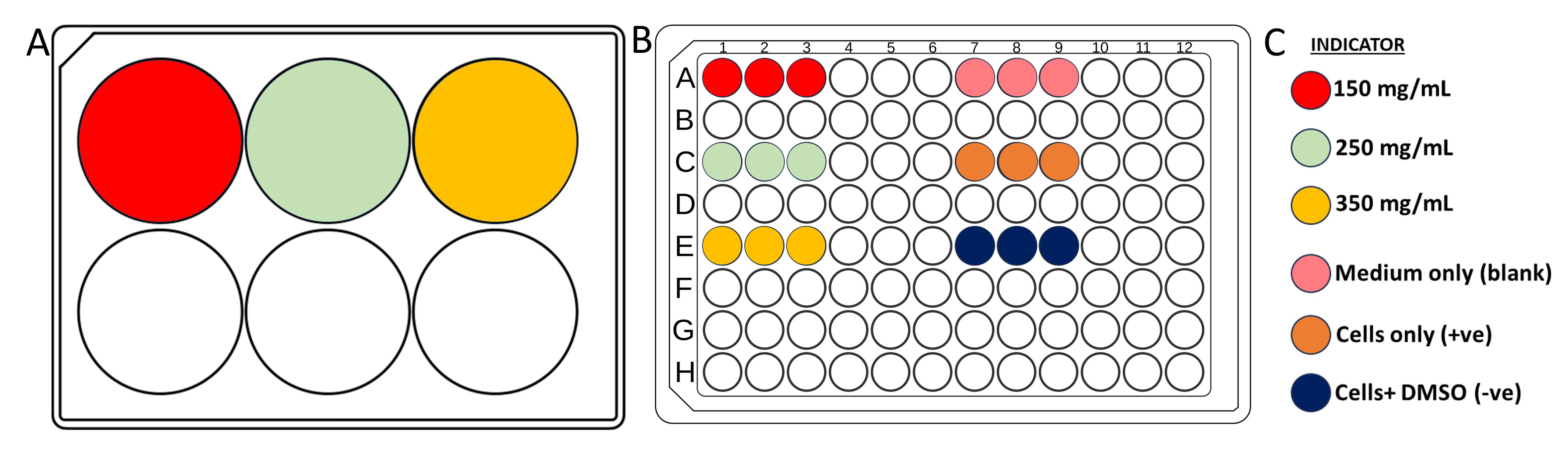
Figure 2. Planning of well plates used in the Alamar blue assay. (A) 6-well plate for hydrogel extraction of three different concentrations with color indication. (B) 96-well plate for cell seeding in Alamar blue assay with color indication. (C) Color legend.
11. Incubate the hydrogel extraction plate and cell plates at 37 ˚C and 5% CO2 with 95% air (standard cell growth conditions) for 24 h.
12. Afterward, discard the old medium from the well plate and exchange with hydrogel extracts (100 μL per well).
13. Incubate the cell extract plate for another 24 h under standard cell growth conditions.
14. The next day, prepare AB mix by adding 10% of AB solution to fresh complete cell culture media (see Recipe 8).
15. Discard the incubated extract medium from each well. Replace with AB mixture (100 μL). Cover the plate with aluminum foil (dark conditions). Incubate the plate under the same standard cell culture conditions for another 2 h.
16. After 2 h of incubation, oxidized resazurin is reduced to fluorescent resorufin. The reduced environment of the cytosol inside the cells is responsible for fluorescence detection.
17. Transfer the AB-treated medium into another 96-well plate. Fill the well with another fresh hydrogel extract to incubate until the next time point is tested.
18. Read the absorbance of each well by using a plate reader at a wavelength of 530–590 nm at 24, 48, and 72 h.
19. Plot the absorbance reading as a bar graph. Figure 3 shows the representative results of hydrogel viability and proliferation evaluation.
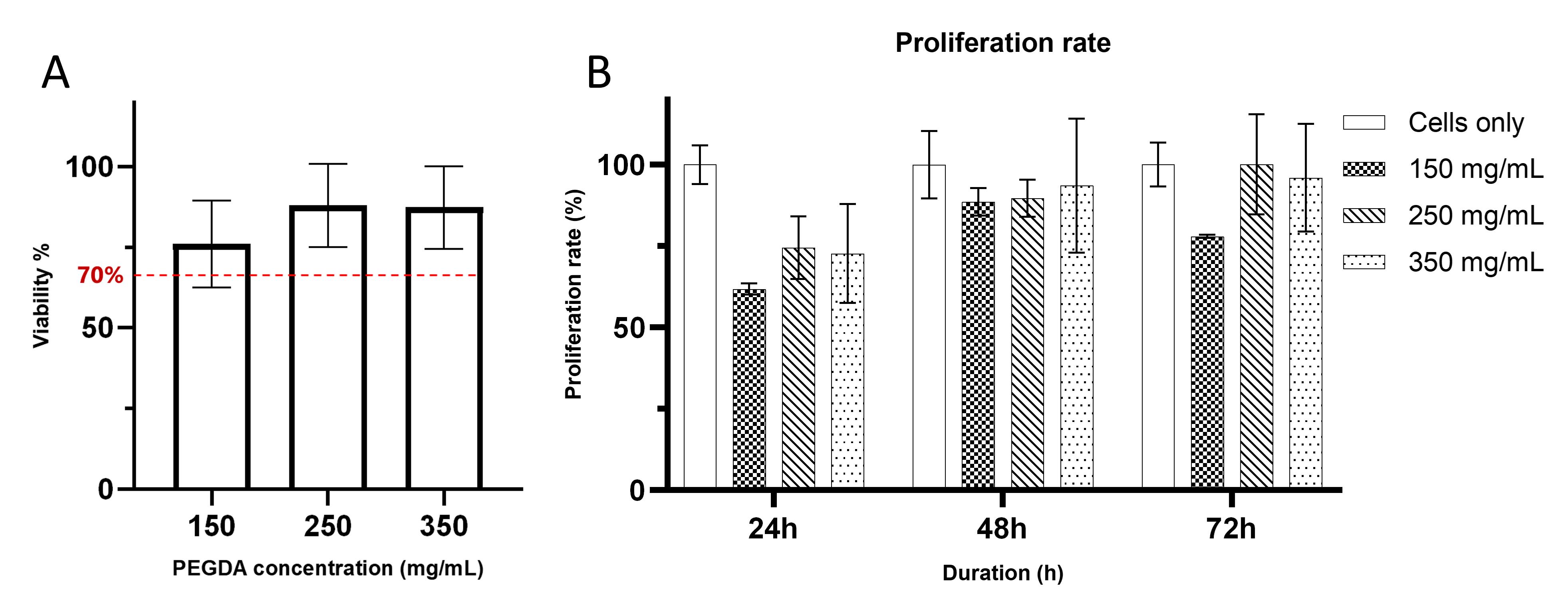
Figure 3. PEGDA viability and proliferation evaluation. (A) Representative result of hydrogel viability graph of three different hydrogel formulations to evaluate cytocompatibility of cells using the Alamar blue assay, where the red dashed line represents 70% of viability threshold following the guideline set by ISO 109993-5 [18]. (B) Cell proliferation rate within three consecutive days to support cell viability. Each bar shows the mean of triplicates ± SD.
F. Surface stiffness measurement
1. Three different concentrations of PEGDA are used to develop different hydrogel stiffnesses. This can be done by varying PEGDA concentration at 150, 250, and 350 mg/mL (v/v) while retaining a constant PLL concentration at 100 mg/mL (w/v).
2. For the production of the hydrogels, follow the same steps as in Section C.
3. After polymerization, mount the PEGDA hydrogels, incubate them with a 1% solution of BSA in PBS (see Recipe 13) for 1 h at room temperature before the measurement, and wash three times with PBS to reduce probe sticking.
4. Indent the samples with 5 μm using the displacement control mode of the Chiaro Nanoindenter. Perform two matrix scans with 4 × 4 positions for each hydrogel using a probe tip of radius 25 μm and stiffness 0.22 N/m.
5. Only successful indentations are included in the analysis. Calculate the Young’s modulus according to the Hertzian contact model using DataViewer software (V2, Optics11 Life) and then plot as a bar chart. Figure 4A shows the representative results of the hydrogel surface stiffness evaluation.
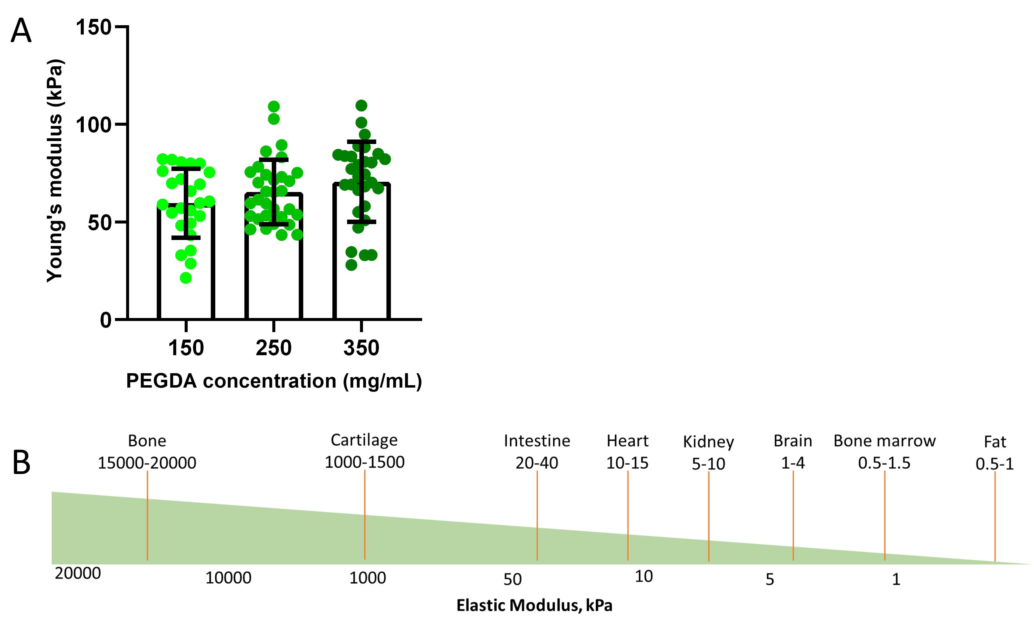
Figure 4. PEGDA surface stiffness evaluation. (A) Hydrogel stiffness measurements of three different concentrations of developed PEGDA hydrogels. Each value is the mean of 25 points (left bar, 150 mg/mL), 32 points (middle bar, 250 mg/mL), and 30 points (right bar, 350 mg/mL) ± SD. (B) Illustration of elastic modulus approximation value of human tissues adapted from Handorf et al. [19].
G. Fabrication of micropattern master
Note: This project used four types of motifs, named as 0°-ridge, 60°-ridge, 0°-island, and 60°-island.
1. Design the micropatterns using QCAD software on a micrometer scale and send them to the Microfluidic Core Facility, Institute of Molecular Systems Engineering and Advanced Materials (IMSEAM), Heidelberg, Germany.
2. The micropattern master’s fabrication uses maskless lithography. Figure 5 illustrates the difference between conventional photolithography and maskless lithography.
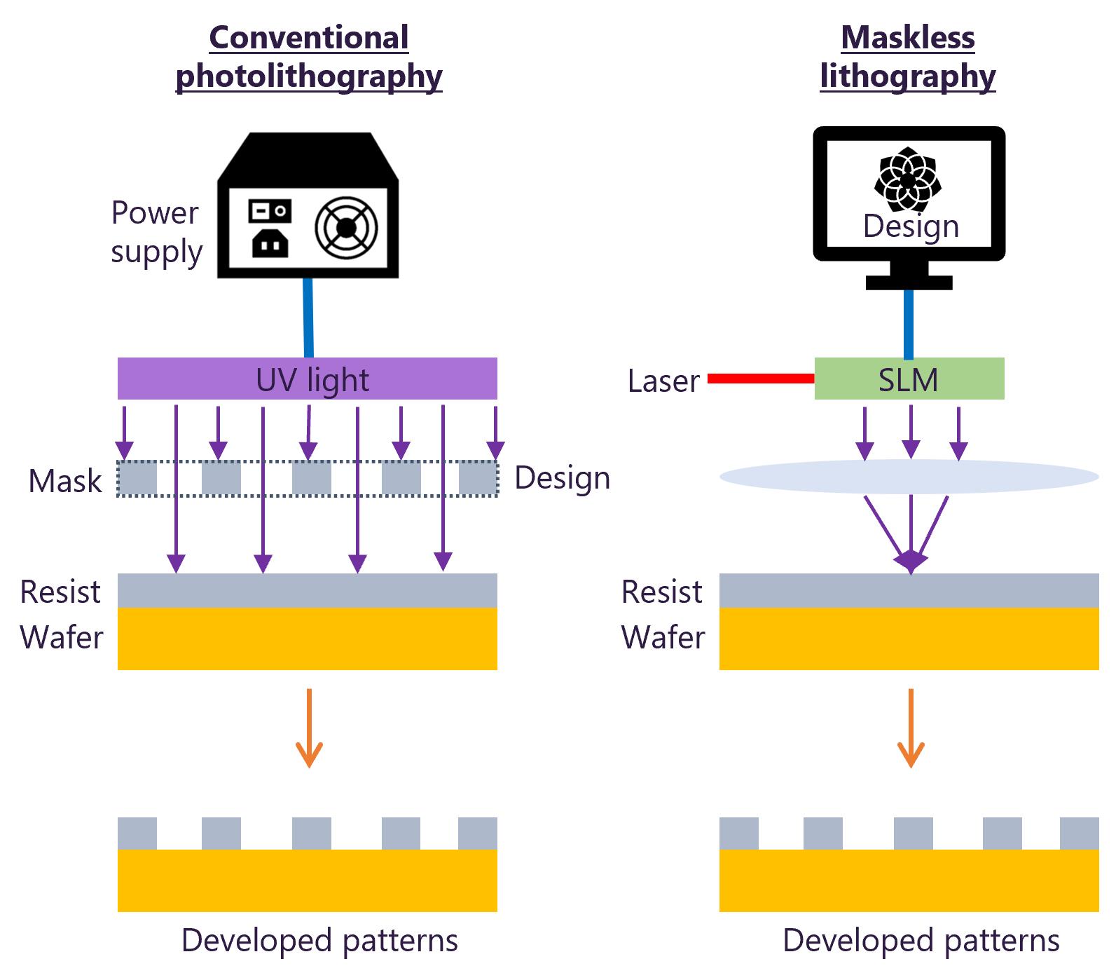
Figure 5. Key differences between conventional photolithography and maskless lithography techniques. Adapted from Kiani et al. [21].
3. Spin-coat a 2” silicon wafer with a negative photoresist (SU 8 3010) to achieve a uniform 10 μm layer.
4. Then, place the wafer onto the machine’s platform to expose the micropattern designs directly onto the silicon wafer to generate the master. Figure 6 shows the micropattern designs and surfaces of the fabricated micropattern masters.
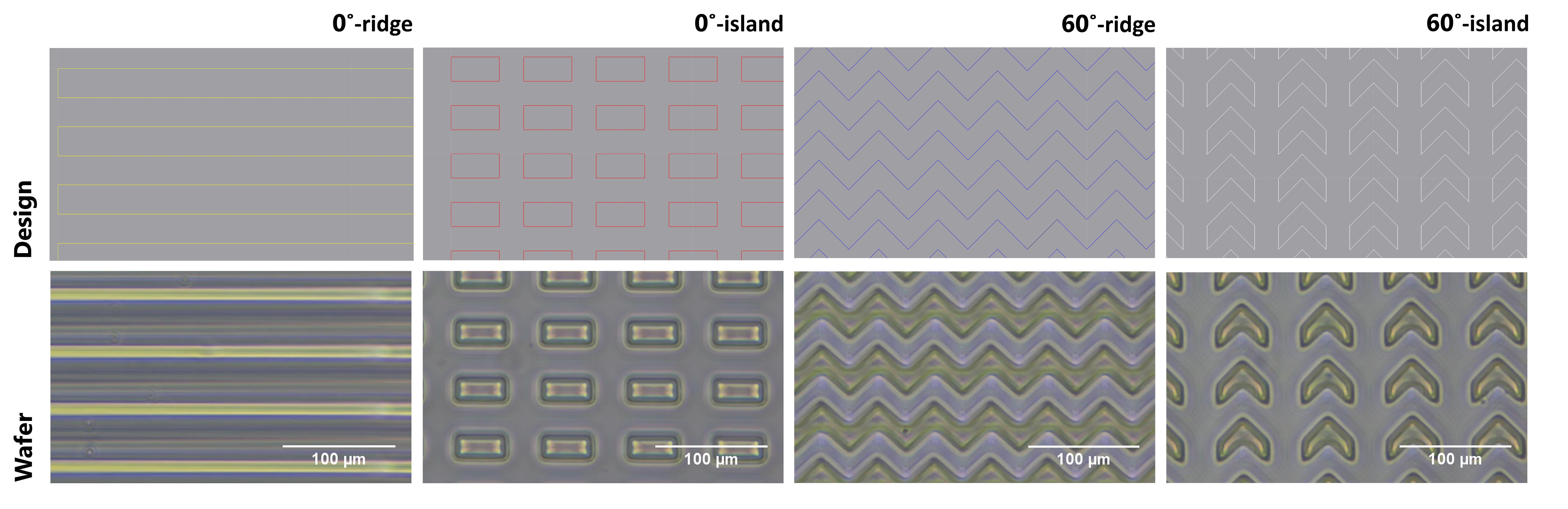
Figure 6. Fabrication of micropattern master using maskless photolithography. First row: micropattern designs consisting of 0°- and 60°-ridge and island motifs, which were designed using QCad software. Second row: micropattern master on the silicon wafer after fabrication directly from a design consisting of 0°- and 60°-ridge and island motifs.
H. Fabrication of PDMS mold
1. Prepare the PDMS precursor consisting of Sylgard 184 elastomer base and its curing agent in a 10:1 ratio by mass.
2. First, weigh 50 g of Sylgard 184 elastomer base and 5 g of curing agent in a weighing pan (see Recipe 14).
3. Mix them thoroughly using a glass rod until homogeneous.
4. Place the silicon micropattern master into a 60 mm diameter Petri dish.
5. For the fabrication, pour the PDMS precursor until it covers the surface of the silicon master and place it inside the vacuum desiccator to remove air bubbles for at least 1 h or until there are no bubbles visible.
6. Store the leftover PDMS precursor at -20 °C for further use.
7. After desiccating, cure the Petri dish with the PDMS precursor inside the oven at 70 °C for at least 1 h or until fully solidified.
8. After solidification, cut the PDMS according to the pattern outline using a scalpel. For better cutting, wet the PDMS with ethanol to create gaps and more easily separate the PDMS from the master.
9. The silicon wafer master can be used to fabricate multiple PDMS copies by filling them with PDMS precursors using the same method (steps G1–8).
10. Subject each cut piece to PDMS micropatterning.
I. PDMS micropatterning
1. Prepare PEGDA precursor by mixing PEGDA (250 mg/mL) in ultrapure water, PLL (100 mg/mL) in 0.15 M NaOH, and 5% photoinitiator (Pi).
2. Briefly disinfect the PDMS molds with different micropattern motifs with 70% ethanol and dry them using nitrogen flow (see Recipe 7).
3. Then, pipette 40 μL of PEGDA precursor onto each PDMS mold and mount the silanized side of the coverslip down, sandwiching PEGDA in between.
Note: The volume of PEGDA hydrogel precursor that is used in this protocol is only suitable for coverslips with 20 mm × 20 mm and 18 mm × 18 mm. It is advisable to increase or decrease the volume of PEGDA hydrogel precursors if using coverslips much bigger or much smaller than the recommended size.
4. Place the silanized coverslip-PEGDA-PDMS assembly carefully inside the UV crosslinker chamber for 20 min. Then, incubate the assembly inside an oven at 37 ˚C overnight.
5. Next, carefully separate each coverslip from its PDMS mold, leaving the PEGDA hydrogel that resembles the patterned microstructures on the surface of the silanized coverslip. Figure 7 shows the representative result of micropattern transfer.
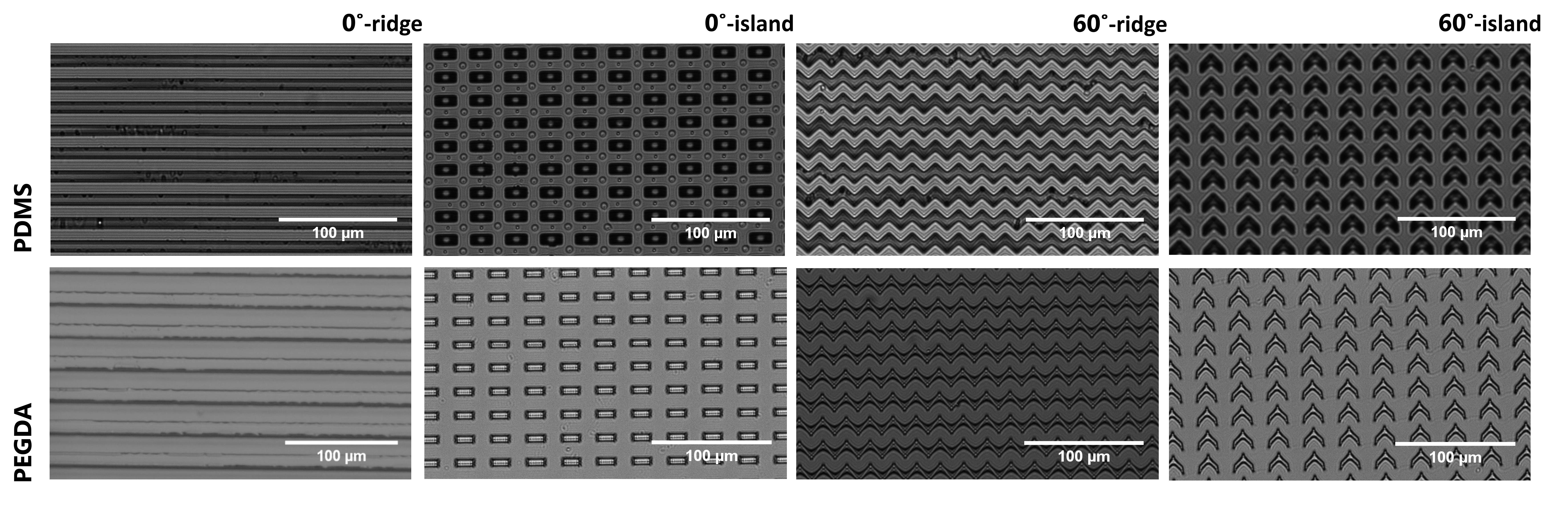
Figure 7. Representative result of micropattern transfer. First row: images of negative micropattern resemblance after pattern transfer between the silicon master and the PDMS mold producing micropatterns. Second row: images of patterned PEGDA hydrogel using the PDMS mold resembling the original micropatterns.
6. Prepare fibronectin solution by mixing fibronectin (50 μg/mL) and fibrinogen (10 μg/mL) in a 10 mM HEPES buffer (see Recipe 11).
7. Bio-functionalize each surface of micropatterned PEGDA hydrogel with fibronectin solution overnight at 37 °C.
8. The next day, wash the fibronectin-incubated hydrogels with PBS to remove excess fibronectin and slow-dry the surfaces using a nitrogen gas gun before subjecting them to cell seeding.
J. Cell immunostaining
1. Observe seeded cells left overnight on micropatterns or flat hydrogel surfaces under a microscope to assess their readiness for immunostaining.
2. First, discard the used culture medium from each well. Wash seeded cells three times with 1 mL of 1× PBS by gently pipetting up and down.
3. After washing, fix cells with 4% PFA by adding 400 μL into each well and allowing it to treat for 15 min at room temperature.
4. Meanwhile, prepare the staining solution by mixing phalloidin and Hoechst in 5% BSA (see Recipe 12) in ratios of 1:200 and 1:1,000, respectively (see Recipe 15).
5. After 15 min of fixation, discard PFA and rinse each well with 1× PBS.
6. Using a scalpel, carefully remove the coverslips from the bottom of each well to prevent the coverslip from breaking.
7. Pipette 100 μL of staining solution into each coverslip.
8. Incubate the cells in the staining solution for 1 h at room temperature. Then, wash three times with 1× PBS.
9. Pipette 20 μL of Mowiol onto a slide and mount the stained coverslip with cells.
10. Label the microscope slides accordingly. View cells under a fluorescence microscope (Delta Vision).
Data analysis
The Alamar Blue indirect assay is used to assess cell viability and proliferation. Hydrogel extracts were prepared at three different concentrations and incubated with the cells. Each experimental group was prepared in triplicate and incubated with Alamar blue solution. Spectrophotometric readings were taken between 530 and 590 nm at three time points: 24, 48, and 72 h. The assay is based on the detection of oxidized resazurin, which is reduced to fluorescent resorufin in the intracellular environment. The reduction occurs in the cytosolic environment of viable cells, generating fluorescence detectable by the spectrophotometer. Data from these readings were tabulated and represented as percentage bar graphs using GraphPad Prism. Cell viability assessment followed the guidelines set by ISO 10993-5 [18], where a viability threshold of 70% is considered compatible (Figure 3A). For surface stiffness measurements, hydrogels were formulated with three different concentrations of PEGDA to modulate surface stiffness. Indentation measurements were done with a nanoindenter by measuring 32 points on each hydrogel surface. The resulting data were used to calculate Young’s modulus, which was then graphically represented as a bar graph using GraphPad Prism. Surface stiffness approximations were based on the average of the indentation points: 150 mg/mL (25 points), 250 mg/mL (30 points), and 350 mg/mL (32 points) (Figure 4A). All immunofluorescent images were captured with a Delta Vision fluorescence microscope at 60× magnification in brightfield mode, with red, green, and blue channels included. Images were stacked to generate overlays, with actin and fibronectin staining assigned to the red channel and nuclear staining assigned to the blue channel.
Validation of protocol
This protocol or parts of it have been described, used, and validated in the following research articles:
• Azioune et al. [35]. Protein micropatterns: A direct printing protocol using deep UVs. Methods in Cell Biology. 97: 133–146.
• Hahn et al. [36]. Photolithographic patterning of polyethylene glycol hydrogels. Biomaterials. 27(12): 2519–2524.
• Subramani. [37]. Fabrication of hydrogel micropatterns by soft photolithography. In: Emerging nanotechnologies for manufacturing (pp. 279–293). William Andrew Publishing.
• Théry, M. and Piel, M. [38]. Micropatterning in Cell Biology, Part C. Academic Press.
• Zambarda et al. [20]. Epithelial cell cluster size affects force distribution in response to EGF-induced collective contractility. European Journal of Cell Biology. 101(4): 151274.
General notes and troubleshooting
Initially, this study sought to implement UVO micropatterning on the protocol established by Zambarda et al. [20]. In their methodology, the surface was first coated with a precursor solution of PLL-PEG hydrogel, which was meticulously applied onto a chromium mask. Subsequently, PLL-PEG was substituted with PEGDA as the coating material in the UVO micropatterning process, with the aim of testing its compatibility using a similar approach. Despite following the established patterning method, a significant challenge was encountered when using PEGDA. After polymerization, the PEGDA hydrogel could not be easily detached from the chromium mask, even with extensive application of water. This behavior was a stark contrast to PLL-PEG patterning, where detachment occurred effortlessly. Our repeated attempts to detach the hydrogel jeopardized the chromium mask’s state, as the force applied pressurized its surface and led to potential scratching. Although the hydrogel was eventually separated, the developed hydrogel exhibited instability, swelling immediately upon contact with water and undermining its structural integrity (Figure 8).
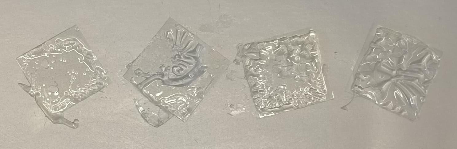
Figure 8. Structural instability of PEGDA hydrogels, which are unable to form stable structures and instantly swell after water contact
These issues indicated that direct patterning of PEGDA via this approach was not feasible and would require substantial troubleshooting in both the patterning technique and the composition of the hydrogel to achieve the desired results. To explore alternative methods, attention was turned to another approach, which was also described by Zambarda et al. [20]. Their method utilizes microcontact printing of fibronectin onto a substrate. In this protocol, PLL-PEG coating, as developed in the previously mentioned procedure, was also employed after being backfilled with fibronectin. In this method, the primary substrate is a polyacrylamide (PAA) hydrogel, cast onto a silanized coverslip. The PAA precursor was mounted with the PLL-PEG-coated surface to transfer fibronectin, and the resulting “sandwich” of hydrogel layers was allowed to polymerize at room temperature. The principle behind this sandwiching technique is that the fibronectin from the upper coverslip (PLL-PEG) makes contact with the PAA hydrogel and, after separation, leaves behind patterned fibronectin islands on the surface of the hydrogel [20,22,23]. This alternative method was attempted once more, but this time, it was done by substituting PAA hydrogel with PEGDA to evaluate its suitability for the micropatterning approach.
To optimize the method for PEGDA, several modifications were made, including varying the hydrogel polymerization duration. Additionally, the steps were modified by first polymerizing the PEGDA on one surface before later sandwiching it with a PLL-PEG hydrogel containing fibronectin. However, it contrasted with the original method of letting the polymerization and transfer occur simultaneously. The rationale behind this modification is that by stamping the PLL-PEG hydrogel onto the polymerized PEGDA surface, the fibronectin would be transferred [22,23]. However, it was observed that the fibronectin transfer efficiency to the PEGDA surface was below 70%, which was deemed insufficient for effective micropatterning.
Although this alternative method did achieve some degree of fibronectin transfer, several flaws remain. The transfer yielded fibronectin islands with only subtle topographical effects, whereas the goal was to develop a method that could create more pronounced topography. At this point, it can be assured that PEGDA hydrogel has potential as a substrate, but further troubleshooting is required, specifically in the hydrogel structure, the efficiency of fibronectin transfer, and topography development. Therefore, the next goal is to identify materials that can enhance the stability of PEGDA hydrogel and improve its ease of patterning and handling. To this end, the polymerization process relied solely on the role of PLL. However, it appeared inadequate in maintaining the structural integrity of the hydrogel. In this pursuit, there is potential to incorporate a PLPP gel photoinitiator (Pi) into the hydrogel formulation, primarily to induce polymerization under UV light [24–26]. Interestingly, the addition of Pi not only facilitates polymerization but also improves the hydrogel’s structural stability, resulting in a more robust structure. This makes it highly suitable for efficient patterning and handling.
To begin with, the reference protocol established by Zambarda et al. [20] was employed once again. This protocol was modified by revising the components of the hydrogel precursor. Previously, the original formulation consisted solely of PEGDA, diluted in water, and mixed with PLL, diluted in sodium hydroxide. In the revised version, an additional 5% Pi was introduced to the precursor mixture before casting it onto a chromium mask. The subsequent steps for patterning the hydrogel in a UVO cleaner remained consistent with the original approach. As a result, a PEGDA hydrogel was successfully produced, which not only detaches from the mask but also exhibits enhanced structural stability and robustness, significantly improving its handling properties. This hydrogel is expected to be safe for cellular use based on ISO 109993-5 guidelines (more than 70% viable) (Figure 3A). The stiffness of this hydrogel also lies at a promising range, which is around 60–70 kPa, between soft and hard tissues in the body (Figure 4).
After fibronectin backfilling, fibrinogen labeling intensity was measured, which served as a direct indicator of fibronectin deposition in the unoccupied regions of the patterns. Fibronectin deposition within smaller island circles was more uniform and comprehensive compared to larger island circles. In the larger island circles, the fibronectin tended to accumulate around the circumference, whereas the smaller island circles exhibited a more even distribution throughout. These findings suggest that the deposition technique is significantly more efficient than the stamping method for applying fibronectin. Additionally, cell adhesion on the functionalized patterns further validated the efficacy of the deposition method in inducing cell adhesion.
Thus far, challenges related to fibronectin transfer efficiency and hydrogel structure stability have been addressed through the application of deposition techniques and the incorporation of Pi into the hydrogel formulation, respectively. The remaining challenge is developing a substrate with pronounced topographical effects, which is essential for this investigation into the relationship between topography and cellular response. To address this, a protocol utilizing polydimethylsiloxane (PDMS) was implemented to create a topographic mold from the micropattern master. For this project, two distinct types of micropatterns were incorporated: ridge-oriented and island-oriented patterns. Both designs featured 0˚ and 60˚ angular motifs.
While conventional tissue engineering approaches often rely on simple, widely used shapes such as rectangular ridges [27,28], circular patches [29], and triangular islands [30], the proposed micropatterns are unique. Angular motifs were introduced into the topography of both ridge and island orientations, while retaining the classic rectangular ridges and islands for comparative purposes. This innovative approach is a distinguishing aspect of the study and adds complexity to the exploration of how topographical features influence cellular behavior.
On a previous attempt, significant challenges were encountered in fabricating the silicone master, leading to imprecise and poorly defined pattern transfers onto both PDMS and hydrogel substrates. Initially, conventional photolithography techniques were utilized for silicone master fabrication. However, issues with the etching process during development resulted in surface defects, as illustrated by the etching profile in Figure 9.
Note: The differences in micropattern motifs contributed to the challenges of developing simultaneous microtopography on silicone wafer, since each motif had its own developing duration; as such, it is advisable not to develop micropatterns simultaneously unless they present the same motifs.
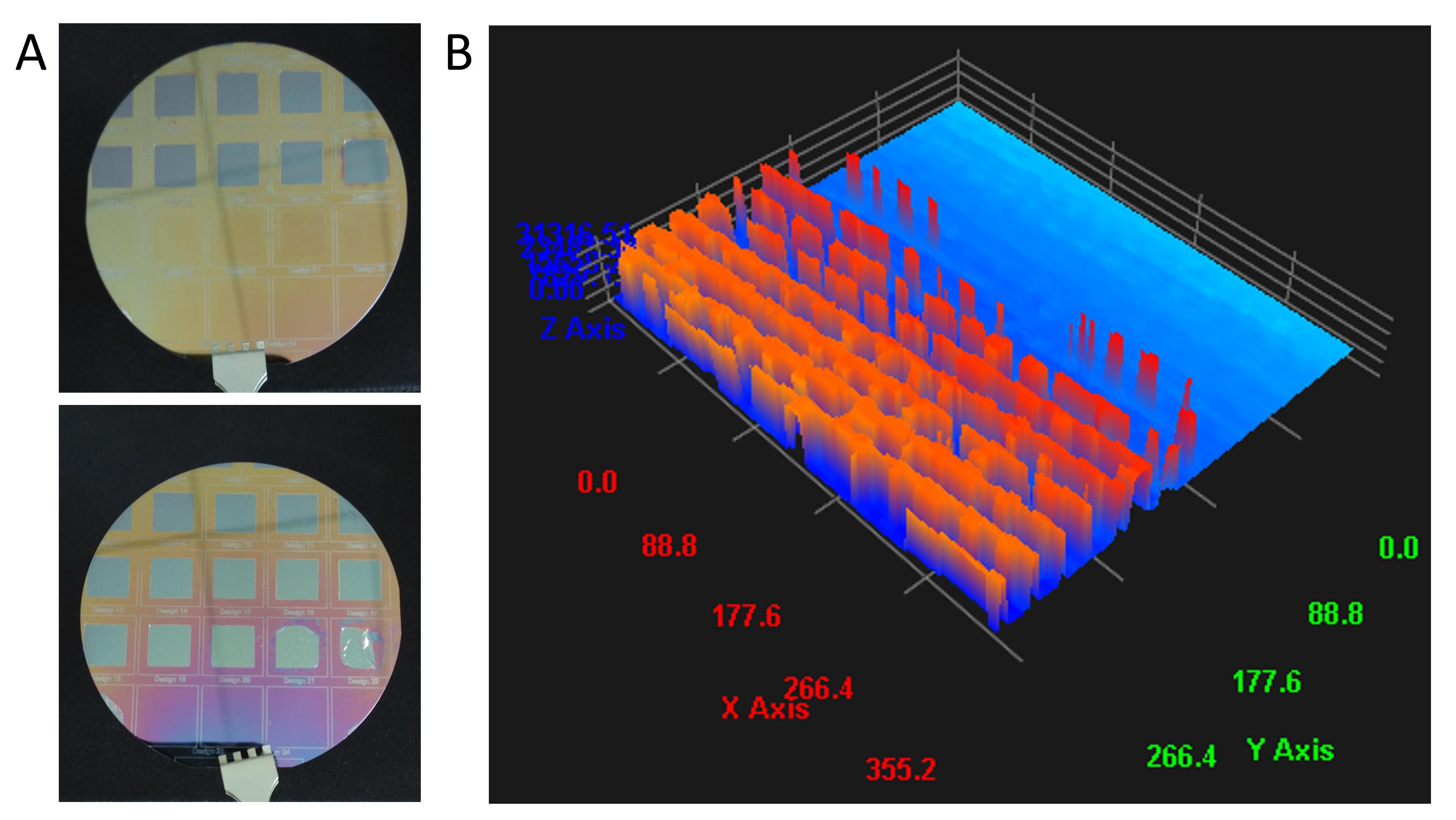
Figure 9. Representative issues encountered during the development of micropattern masters. (A) Undeveloped photoresist from the silicone master surface. (B) Etching profile of silicone master surface after using conventional photolithography to see the details of surface defects.
To address this, a transition was made that employed inductively coupled plasma-reactive ion etching (ICP-RIE) for the silicone master fabrication process. Unlike wet etching, ICP-RIE employs dry etching to remove unwanted material from the wafer following UV exposure [31]. This process generates plasma using radio frequency (RF) power within a magnetic field, significantly increasing the etching precision [32]. The use of high-density ion sources enhances the etching rate, while the application of a separate RF bias to the substrate (silicon wafer) creates a directional electric field, enabling a more anisotropic etch profile [32]. This approach has markedly improved pattern fidelity and precision in the silicone masters. It was demonstrated that using ICP-RIE in the etching process improved the development of micropatterns compared to conventional photolithography, as evidenced by surface profilometer measurement (Figure 10B, D).
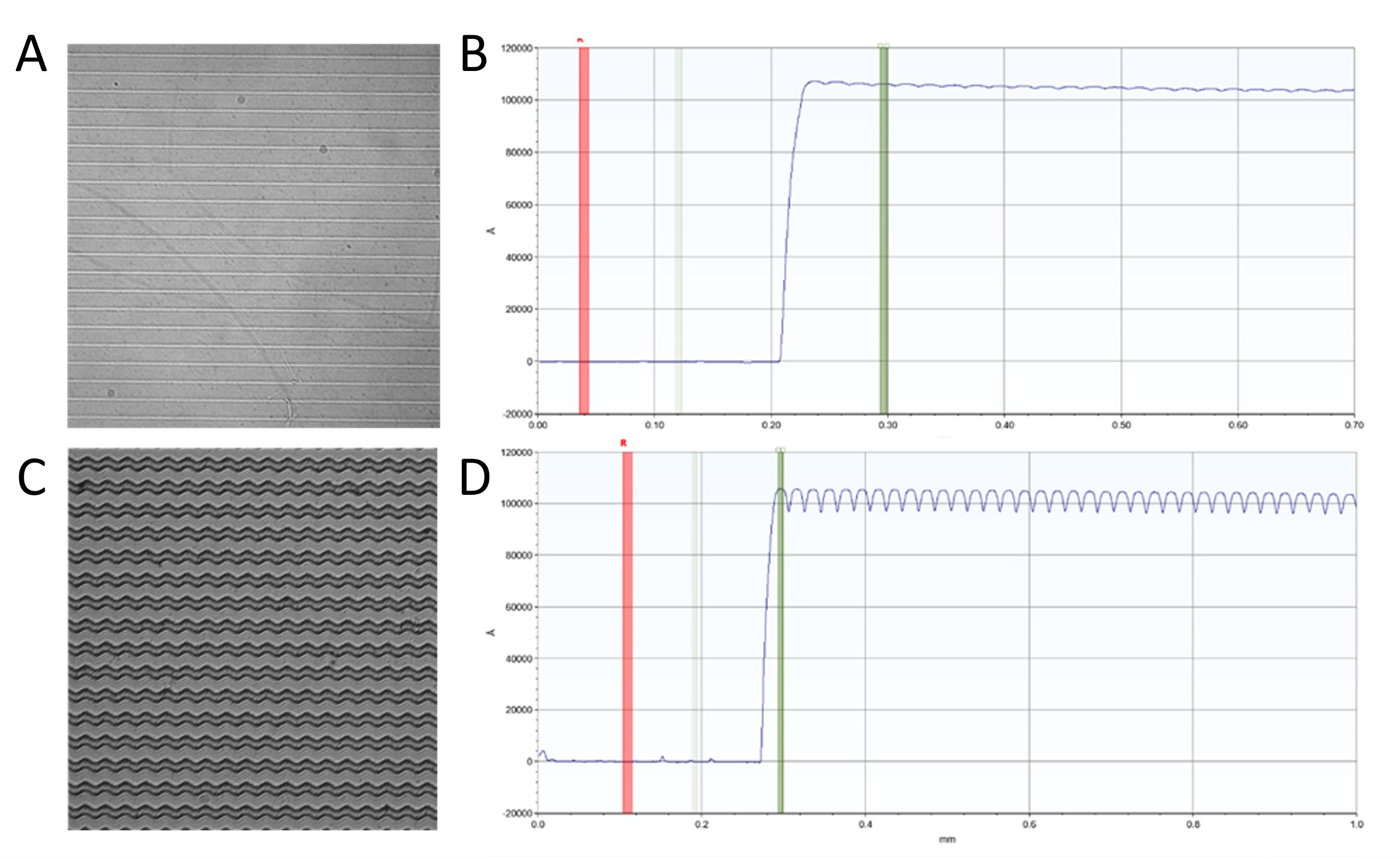
Figure 10. Representative observation of the improvement of the etching process using ICP-RIE. (A) Surface profile of the 0°-ridge pattern. (B) Profilometer measurement of the 0°-ridge. (C) Surface profile of the 60°-ridge pattern. (D) Profilometer measurement of the 60°-ridge pattern.
However, during the production of PDMS molds, uneven and low-precision topography was observed, indicating that further optimization of the etching process was still necessary. Figure 11 highlights these surface imperfections on the PDMS after pattern transfer.
Note: The issue with the micropattern master, developed using ICP-RIE, is that the developed microtopography tends to stick to the solidified PDMS in the separation process.
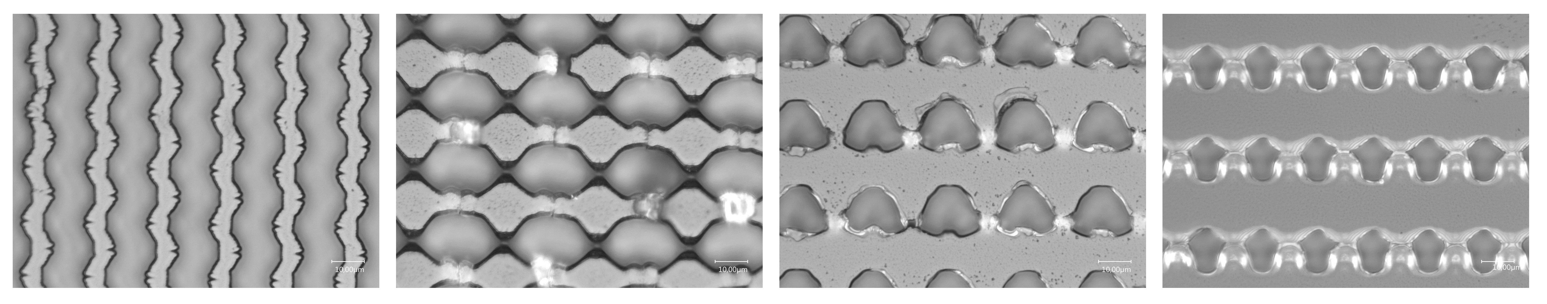
Figure 11. Representative images of surfaces having imprecise pattern transfers from the silicone master to the PDMS surface
To overcome this, maskless lithography is seen as a potential alternative for silicone master fabrication. This technique allows for the direct projection of micropattern designs onto resist-coated wafers using UV radiation or electron beams, eliminating the need for physical masks [33,34]. By doing so, it enables a highly precise structuring process, resulting in superior replication quality. Unlike the labor-intensive combination of conventional photolithography and ICP-RIE, maskless lithography streamlines the fabrication process and significantly reduces production time.
As shown in the surface comparison in Figures 6 and 7, this approach yielded higher precision and quality in micropattern transfer, particularly in the PEGDA hydrogel fabrication, as the main goal. To achieve PDMS-based micropatterning, a method was established where PEGDA hydrogel was cast onto a PDMS mold and crosslinked using a UV crosslinker chamber, followed by slow curing in an oven at 37 ˚C overnight. After the hydrogel was produced, the surface was biofunctionalized with fibronectin and prepared for cell seeding. The fibronectin binds to the PEGDA hydrogel by anchoring to the PLL chain. Since this technique involves fibronectin deposition, uniform fibronectin coverage across the entire PEGDA surface was expected, providing cells with the flexibility to migrate either on the ridges/islands or along the lower surface of the grooves. To verify fibronectin deposition on the hydrogel surface, fibrinogen was labeled from the fibronectin pocket. As depicted in Figure 12, there is a marked intensity contrast between the ridges/islands (higher red intensity) and the grooves (lower red intensity), indicating distinct topographical height differences.
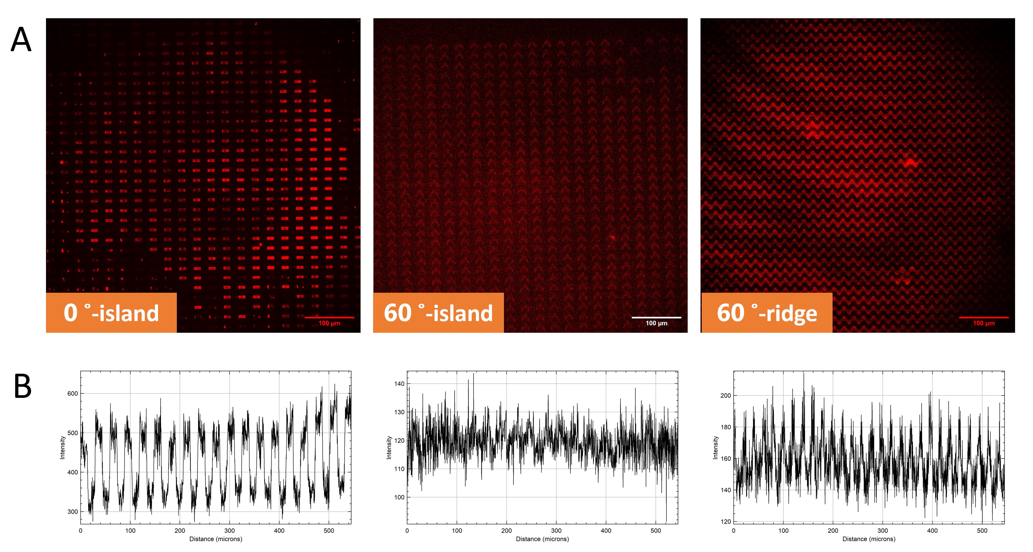
Figure 12. Establishment of PDMS-based micropatterning. (A) Fibronectin deposition on PEGDA hydrogel surface. Red staining indicates fibrinogen labeling on the fibronectin pocket. (B) Fluorescence intensity graph, showing the intensity of fibronectin on ridges/islands and grooves.
In this study, PEGDA hydrogel introduces a promising strategy for utilizing substrate topography and geometry as instructive cues to guide cellular organization within their native environment. These findings, particularly through immunofluorescent staining, demonstrate that this hydrogel can influence various aspects of cellular responses, including cell morphology (Figure 13), elongation (Figure 14), alignment (Figure 14), and orientation (Figure 15), as well as cell preference (Figures 16 and 17).
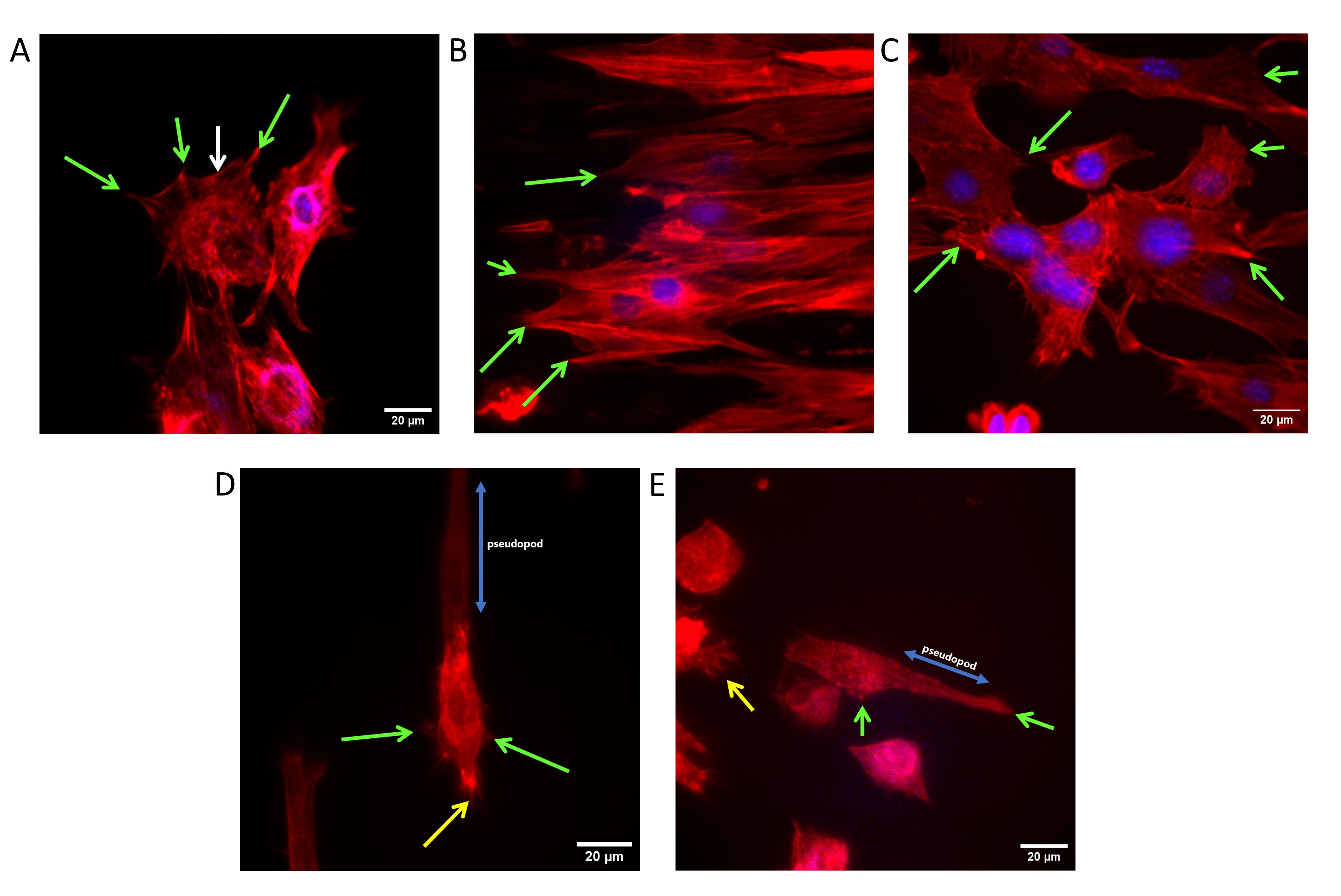
Figure 13. Influence of topography on cell morphology. (A) Cells on a flat surface. (B) Cells on 0˚-ridge. (C) Cells on 60˚-ridge. (D) Cells on 0˚-island. (E) Cells on 60˚-island. Green arrows indicate the focal adhesion, the white arrow indicates the transverse arc of a cell, yellow arrows indicate multiple formations of filopodia, and blue arrows indicate pseudopod formation.
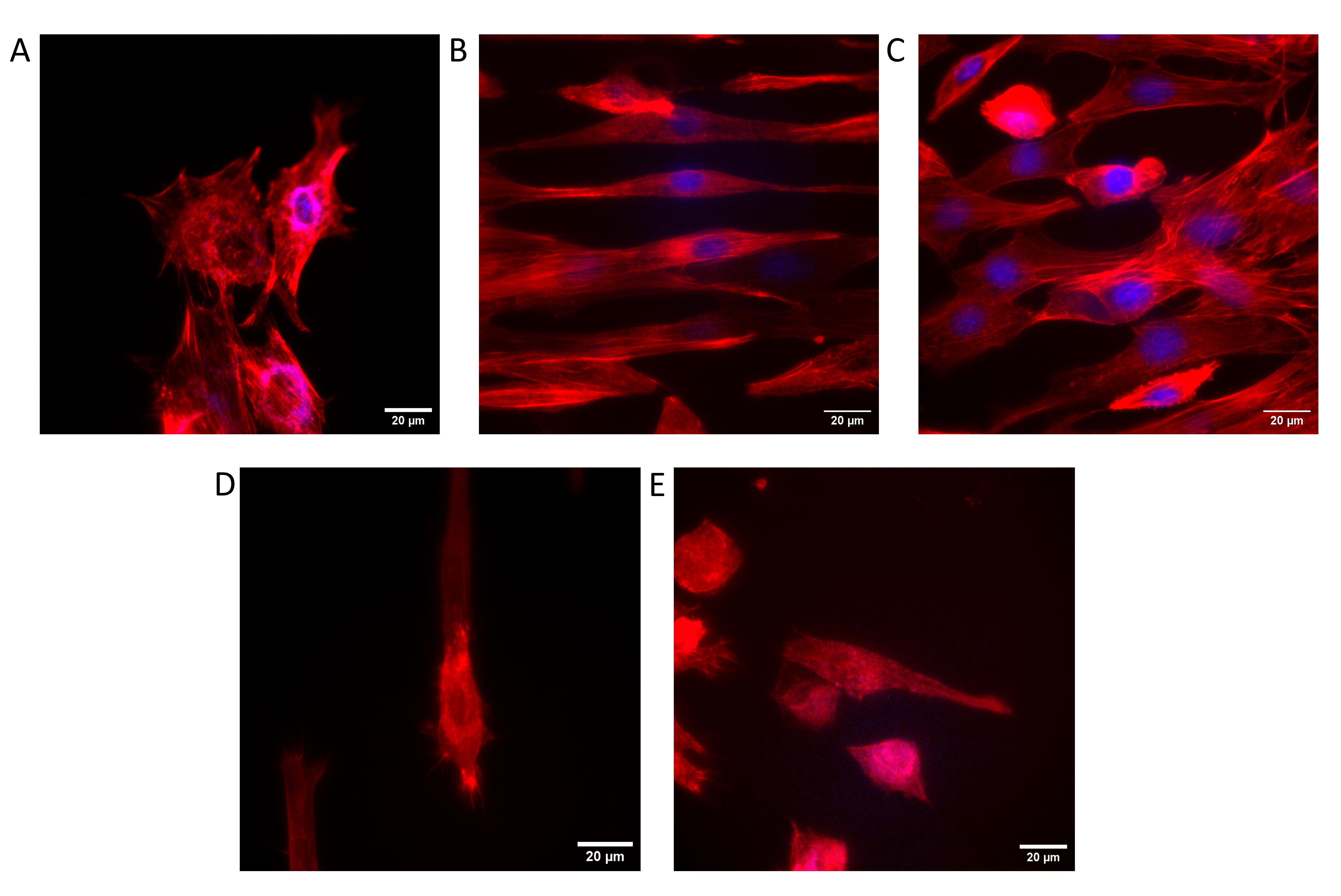
Figure 14. Influence of topography on cell elongation and alignment. (A) Cells on a flat surface. (B) Cells on 0˚-ridge. (C) Cells on 60˚-ridge. (D) Cells on 0˚-island. (E) Cells on 60˚-island.
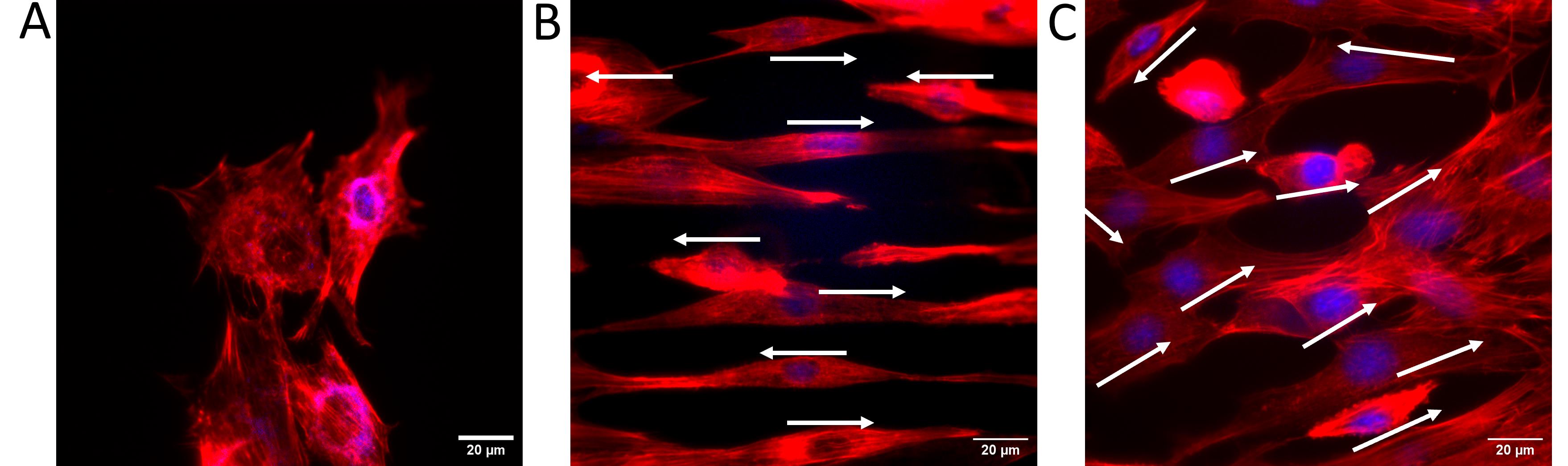
Figure 15. Influence of topography on cell orientation. (A) Cells on a flat surface exhibited no obvious orientation. (B) Cells on 0˚-ridge oriented in parallel. (C) Cells on 60˚-ridge with varied degrees of orientation. White arrows indicate the orientation and direction of each cell.
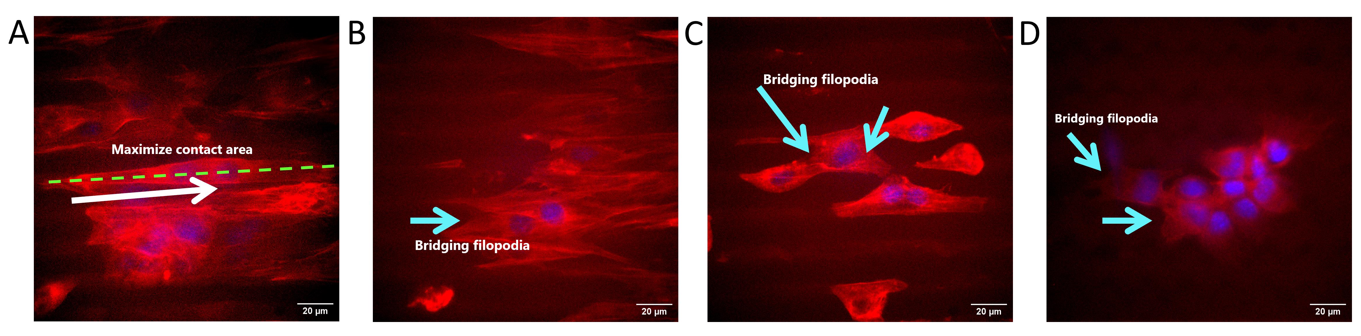
Figure 16. Influence of topography on cell preference. (A) Cells on 0˚-ridge maximized their contact area along the ridges. (B, C) Bridging filopodia event of cells on 0˚-ridge. (D) Bridging filopodia event of cells on 60˚-ridge. The white arrow indicates the direction of cells, and the light blue arrows indicate the bridging filopodia event.
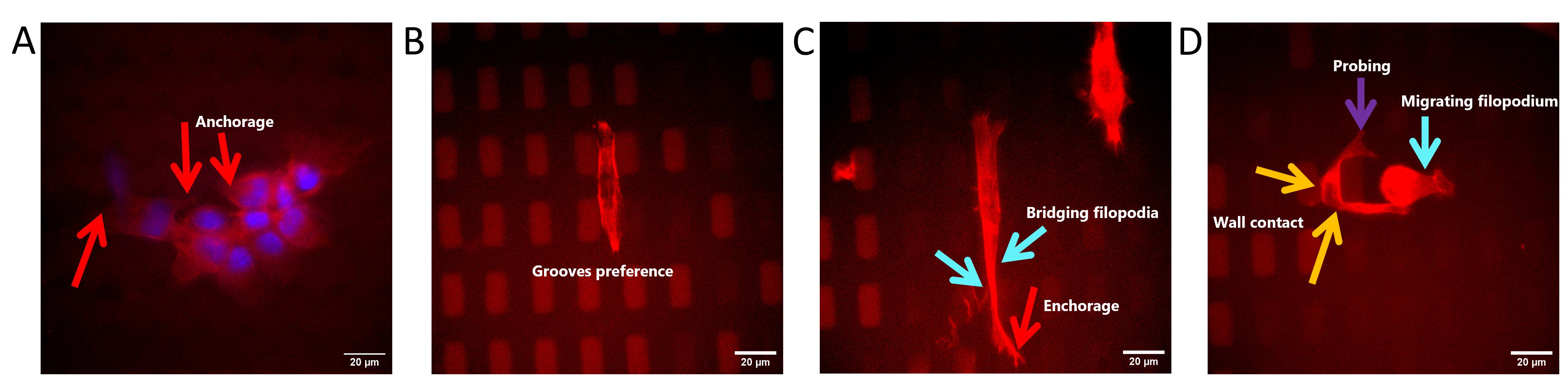
Figure 17. Influence of topography on cell preference. (A) Cells on 60˚-ridge forming anchorage along the edges of the ridges to support their migration. (B) Cells on 0˚-island showing grooves’ migration preference. (C) Cells on 0˚-ridge showing island-to-island migration preference by forming bridging filopodia and anchorage. (D) Cells on 0˚-island with two migration preferences. Red arrows indicate the formation of anchorage of cells on the pattern’s edges, light blue arrows indicate the bridging and migrating filopodia event, orange arrows indicate the wall contact of probing cells, and the purple arrow indicates the cell’s probing.
Acknowledgments
This research project was supported by the European Union’s Horizon 2020 Research and Innovation Programme under the Marie Skłodowska-Curie Grant Agreement (872869). The idea of using angular patterns was supported by The Ministry of Higher Education Malaysia’s Fundamental Research Grant Scheme (203/CIPPT/6711506). MKA Darwis’s education is supported by Malaysia’s Sabah state government scholarship. A special gratitude to all members of BioTUNE consortium, especially to members from Universiti Sains Malaysia (USM), Institut National de la Santé et de la Recherche Médicale (INSERM), Max Planck Institute for Medical Research (MPI), University of Bayreuth, and Universitat Politècnica de Catalunya (UPC) for their dedication and support. A special thanks is also extended to the Microfluidics Core Facility at the Institute for Molecular Systems Engineering and Advanced Materials (IMSEAM), which is partially funded by the Health + Life Science Alliance Heidelberg Mannheim. The Health + Life Science Alliance provided state funds approved by the state parliament of Baden-Württemberg. We also extend our sincere gratitude to the Institute of Nano Electronic Engineering of Universiti Malaysia Perlis and the Low Dimensional Materials Research Centre of Universiti Malaya for their valuable support and provision of research facilities. This protocol describes a method that was established in Azioune et al. [35], Hahn et al. [36], Subramani. [37], Théry and Piel [38], and Zambarda et al. [20].
Competing interests
N.E. Vrana and P. Lavalle are stockholders and employees of SPARTHA Medical. All other authors declare no competing interests.
References
- Muzzio, N., Moya, S. and Romero, G. (2021). Multifunctional Scaffolds and Synergistic Strategies in Tissue Engineering and Regenerative Medicine. Pharmaceutics. 13(6): 792. https://doi.org/10.3390/pharmaceutics13060792
- Tallawi, M., Rosellini, E., Barbani, N., Cascone, M. G., Rai, R., Saint-Pierre, G. and Boccaccini, A. R. (2015). Strategies for the chemical and biological functionalization of scaffolds for cardiac tissue engineering: a review. J R Soc Interface. 12(108): 20150254. https://doi.org/10.1098/rsif.2015.0254
- Leclerc, A., Tremblay, D., Hadjiantoniou, S., Bukoreshtliev, N. V., Rogowski, J. L., Godin, M. and Pelling, A. E. (2013). Three dimensional spatial separation of cells in response to microtopography. Biomaterials. 34(33): 8097–8104. https://doi.org/10.1016/j.biomaterials.2013.07.047
- Geckil, H., Xu, F., Zhang, X., Moon, S. and Demirci, U. (2010). Engineering hydrogels as extracellular matrix mimics. Nanomedicine. 5(3): 469–484. https://doi.org/10.2217/nnm.10.12
- Limongi, T., Tirinato, L., Pagliari, F., Giugni, A., Allione, M., Perozziello, G., Candeloro, P. and Di Fabrizio, E. (2017). Fabrication and Applications of Micro/Nanostructured Devices for Tissue Engineering. Nano Micro Lett. 9(1): 1–13. https://doi.org/10.1007/s40820-016-0103-7
- Lemos, R., Maia, F. R., Reis, R. L. and Oliveira, J. M. (2022). Engineering of Extracellular Matrix‐Like Biomaterials at Nano‐ and Macroscale toward Fabrication of Hierarchical Scaffolds for Bone Tissue Engineering. Adv NanoBiomed Res. 2(2): e202100116. https://doi.org/10.1002/anbr.202100116
- Tamiello, C., Buskermolen, A. B. C., Baaijens, F. P. T., Broers, J. L. V. and Bouten, C. V. C. (2016). Heading in the Right Direction: Understanding Cellular Orientation Responses to Complex Biophysical Environments. Cell Mol Bioeng. 9(1): 12–37. https://doi.org/10.1007/s12195-015-0422-7
- Cheng, B., Lin, M., Huang, G., Li, Y., Ji, B., Genin, G. M., Deshpande, V. S., Lu, T. J. and Xu, F. (2017). Cellular mechanosensing of the biophysical microenvironment: A review of mathematical models of biophysical regulation of cell responses. Phys Life Rev. 22: 88–119. https://doi.org/10.1016/j.plrev.2017.06.016
- Tortorella, I., Argentati, C., Emiliani, C., Martino, S. and Morena, F. (2022). The role of physical cues in the development of stem cell-derived organoids. Eur Biophys J. 51(2): 105–117. https://doi.org/10.1007/s00249-021-01551-3
- Cai, L., Lu, J., Sheen, V. and Wang, S. (2012). Promoting Nerve Cell Functions on Hydrogels Grafted with Poly(l-lysine). Biomacromolecules. 13(2): 342–349. https://doi.org/10.1021/bm201763n
- Hakim Khalili, M., Zhang, R., Wilson, S., Goel, S., Impey, S. A. and Aria, A. I. (2023). Additive Manufacturing and Physicomechanical Characteristics of PEGDA Hydrogels: Recent Advances and Perspective for Tissue Engineering. Polymers. 15(10): 2341. https://doi.org/10.3390/polym15102341
- McAvoy, K., Jones, D. and Thakur, R. R. S. (2018). Synthesis and Characterisation of Photocrosslinked poly(ethylene glycol) diacrylate Implants for Sustained Ocular Drug Delivery. Pharm Res. 35(2): 1–17. https://doi.org/10.1007/s11095-017-2298-9
- Rekowska, N., Teske, M., Arbeiter, D., Brietzke, A., Konasch, J., Riess, A., Mau, R., Eickner, T., Seitz, H., Grabow, N., et al. (2019). Biocompatibility and thermodynamic properties of PEGDA and two of its copolymer. In: 2019 41st Annual International Conference of the IEEE Engineering in Medicine and Biology Society (EMBC). 1093–1096. https://doi.org/10.1109/embc.2019.8857503
- Shen, Y., Xu, G., Huang, H., Wang, K., Wang, H., Lang, M., Gao, H. and Zhao, S. (2021). Sequential Release of Small Extracellular Vesicles from Bilayered Thiolated Alginate/Polyethylene Glycol Diacrylate Hydrogels for Scarless Wound Healing. ACS Nano. 15(4): 6352–6368. https://doi.org/10.1021/acsnano.0c07714
- García, A. E. B., Merino, M. V. F., Tolosa, I. M. G., Muñoz, D. R., López, M. A. C. and Pantoja, R. O. (2020). Polyethylene‐glycol chitosan hydrogel accelerates traumatic wound healing in diabetic mice. FASEB J. 34: 1–1. https://doi.org/10.1096/fasebj.2020.34.s1.04577
- Morris, V. B., Nimbalkar, S., Younesi, M., McClellan, P. and Akkus, O. (2017). Mechanical Properties, Cytocompatibility and Manufacturability of Chitosan:PEGDA Hybrid-Gel Scaffolds by Stereolithography. Ann Biomed Eng. 45(1): 286–296. https://doi.org/10.1007/s10439-016-1643-1
- Nemir, S., Hayenga, H. N. and West, J. L. (2010). PEGDA hydrogels with patterned elasticity: Novel tools for the study of cell response to substrate rigidity. Biotechnol Bioeng. 105(3): 636–644. https://doi.org/10.1002/bit.22574
- Standard, I. (2009). Biological evaluation of medical devices—Part 5: Tests for in vitro cytotoxicity. Geneve, Switzerland: International Organization for Standardization. 10, 9781570203558.
- Handorf, A. M., Zhou, Y., Halanski, M. A. and Li, W. J. (2015). Tissue Stiffness Dictates Development, Homeostasis, and Disease Progression. Organogenesis. 11(1): 1–15. https://doi.org/10.1080/15476278.2015.1019687
- Zambarda, C., Pérez González, C., Schoenit, A., Veits, N., Schimmer, C., Jung, R., Ollech, D., Christian, J., Roca-Cusachs, P., Trepat, X., et al. (2022). Epithelial cell cluster size affects force distribution in response to EGF-induced collective contractility. Eur J Cell Biol. 101(4): 151274. https://doi.org/10.1016/j.ejcb.2022.151274
- Kiani, A., Venkatakrishnan, K., Tan, B. and Venkataramanan, V. (2011). Maskless lithography using silicon oxide etch-stop layer induced by megahertz repetition femtosecond laser pulses. Opt Express. 19(11): 10834. https://doi.org/10.1364/oe.19.010834
- Castaño, A. G., Hortigüela, V., Lagunas, A., Cortina, C., Montserrat, N., Samitier, J. and Martínez, E. (2014). Protein patterning on hydrogels by direct microcontact printing: application to cardiac differentiation. RSC Adv. 4(55): 29120–29123. https://doi.org/10.1039/c4ra03374d
- Tay, C. Y., Wu, Y. L., Cai, P., Tan, N. S., Venkatraman, S. S., Chen, X. and Tan, L. P. (2015). Bio-inspired micropatterned hydrogel to direct and deconstruct hierarchical processing of geometry-force signals by human mesenchymal stem cells during smooth muscle cell differentiation. NPG Asia Mater. 7(7): e199–e199. https://doi.org/10.1038/am.2015.66
- Ferreira, P., J. Coelho, J. F., F., J. and H., M. (2011). Photocrosslinkable Polymers for Biomedical Applications. In: Biomedical Engineering Frontiers and Challenges. 1: 55–74. https://doi.org/10.5772/18752
- Dumur, F. (2020). Recent advances on carbazole-based photoinitiators of polymerization. Eur Polym J. 125: 109503. https://doi.org/10.1016/j.eurpolymj.2020.109503
- Zhou, J., Allonas, X., Ibrahim, A. and Liu, X. (2019). Progress in the development of polymeric and multifunctional photoinitiators. Prog Polym Sci. 99: 101165. https://doi.org/10.1016/j.progpolymsci.2019.101165
- Yu, X., Zhang, D., Liu, C., Liu, Z., Li, Y., Zhao, Q., Gao, C. and Wang, Y. (2021). Micropatterned Poly(D,L-Lactide-Co-Caprolactone) Conduits With KHI-Peptide and NGF Promote Peripheral Nerve Repair After Severe Traction Injury. Front Bioeng Biotechnol. 9: e744230. https://doi.org/10.3389/fbioe.2021.744230
- Sun, L., Pereira, D., Wang, Q., Barata, D. B., Truckenmüller, R., Li, Z., Xu, X. and Habibovic, P. (2016). Controlling Growth and Osteogenic Differentiation of Osteoblasts on Microgrooved Polystyrene Surfaces. PLoS One. 11(8): e0161466. https://doi.org/10.1371/journal.pone.0161466
- Segerer, F. J., Thüroff, F., Piera Alberola, A., Frey, E. and Rädler, J. O. (2015). Emergence and Persistence of Collective Cell Migration on Small Circular Micropatterns. Phys Rev Lett. 114(22): e228102. https://doi.org/10.1103/physrevlett.114.228102
- Geisse, N. A., Sheehy, S. P. and Parker, K. K. (2009). Control of myocyte remodeling in vitro with engineered substrates. In Vitro Cell Dev Biol Animal. 45(7): 343–350. https://doi.org/10.1007/s11626-009-9182-9
- Racka-Szmidt, K., Stonio, B., Żelazko, J., Filipiak, M. and Sochacki, M. (2021). A Review: Inductively Coupled Plasma Reactive Ion Etching of Silicon Carbide. Materials. 15(1): 123. https://doi.org/10.3390/ma15010123
- Huff, M. (2021). Recent Advances in Reactive Ion Etching and Applications of High-Aspect-Ratio Microfabrication. Micromachines (Basel). 12(8): 991. https://doi.org/10.3390/mi12080991
- Traub, M. C., Longsine, W. and Truskett, V. N. (2016). Advances in Nanoimprint Lithography. Annu Rev Chem Biomol Eng. 7(1): 583–604. https://doi.org/10.1146/annurev-chembioeng-080615-034635
- Efremov, A. (2014). Fabrication and application of hydrophilic-hydrophobic micropatterned polymer surfaces. (Doctoral dissertation). https://doi.org/10.11588/heidok.00017070
- Azioune, A., Carpi, N., Tseng, Q., Théry, M. and Piel, M. (2010). Protein Micropatterns. Methods Cell Biol. 97: 133–146. https://doi.org/10.1016/s0091-679x(10)97008-8
- Hahn, M., Taite, L., Moon, J., Rowland, M., Ruffino, K. and West, J. (2006). Photolithographic patterning of polyethylene glycol hydrogels. Biomaterials. 27(12): 2519–2524. https://doi.org/10.1016/j.biomaterials.2005.11.045
- Subramani, K. (2015). Fabrication of hydrogel micropatterns by soft photolithography. In: Emerging Nanotechnologies for Manufacturing. 279–293. William Andrew Publishing. https://doi.org/10.1016/b978-0-323-28990-0.00011-7
- Théry, M. and Piel, M. (2014). Micropatterning in Cell Biology, Part C. Academic Press.
Article Information
Publication history
Received: Feb 24, 2025
Accepted: Apr 18, 2025
Available online: May 8, 2025
Published: May 20, 2025
Copyright
© 2025 The Author(s); This is an open access article under the CC BY-NC license (https://creativecommons.org/licenses/by-nc/4.0/).
How to cite
Darwis, M. K. A., Levario-Diaz, V., Pashapour, S., Voigt, J. L., Lebaudy, E., Sabani, N., Bakar, A. S. A., Vrana, N. E., Lavalle, P., Cavalcanti-Adam, E. A. and Ngalim, S. H. (2025). Development of Polyethylene Glycol Diacrylate-Based Micropattern Substrate to Study the Interplay Between Surface Topography and Cellular Response for Tissue Engineering Applications. Bio-protocol 15(10): e5323. DOI: 10.21769/BioProtoc.5323.
Category
Cell Biology > Cell engineering > Tissue engineering
Biological Engineering > Biomedical engineering
Do you have any questions about this protocol?
Post your question to gather feedback from the community. We will also invite the authors of this article to respond.