- Protocols

- Articles and Issues
- For Authors
- About
- Become a Reviewer

A Human Cervix Chip for Preclinical Studies of Female Reproductive Biology
Published: Vol 15, Iss 7, Apr 5, 2025 DOI: 10.21769/BioProtoc.5262 Views: 2103
Reviewed by: Alka MehraHsih-Yin TanIbrahim AlabriAnonymous reviewer(s)
Original research article
The authors used this protocol in:

May 2024
Advertisement


Protocol Collections
Comprehensive collections of detailed, peer-reviewed protocols focusing on specific topics


Abstract
Pathological conditions of the cervix ranging from cervical cancer to structural dysfunction associated with preterm labor all have limited treatment options. Thus, there is a need for physiologically relevant preclinical models that recapitulate the structure and function of this human organ. Here, we describe a protocol for engineering and studying a highly functional in vitro model of the human cervix that is composed of a commercially available, dual-channel, microfluidic, organ-on-a-chip (Organ Chip) device lined by primary cervical epithelial (CE) cells interfaced across a porous membrane with cervical stromal cells. The provision of dynamic and customized media flow through both the epithelial and stromal compartments results in cell growth and differentiation, including the accumulation of a thick mucus layer overlying the epithelium. The resulting model closely mimics the structure, epithelial barrier, mucus composition and structure, and biochemical properties of the in vivo human cervix, as well as its responsiveness to female hormones, pH, and microbiome. This Cervix Chip protocol also includes noninvasive techniques for longitudinal monitoring of the live 3D tissue model. The Cervix Chip offers a powerful preclinical platform for replicating in vivo cervical physiology, studying disease mechanisms, and facilitating the development of new therapeutics and diagnostics.
Key features
• Creates a functional and physiologically responsive 3D tissue model of the human cervix including a living epithelial–stromal interface.
• Enables longitudinal and endpoint analysis of the epithelial and stromal environment and their respective secretions independently.
• Allows extended clinically relevant studies, such as assessment of tissue barrier function and mucus production as well as co-culture with microbiome and pathogens.
• Uses a commercially available dual-channel microfluidic chip and automated culture system (ZoëTM Culture Module, Emulate Inc., USA).
Keywords: Organ-on-a-ChipGraphical overview
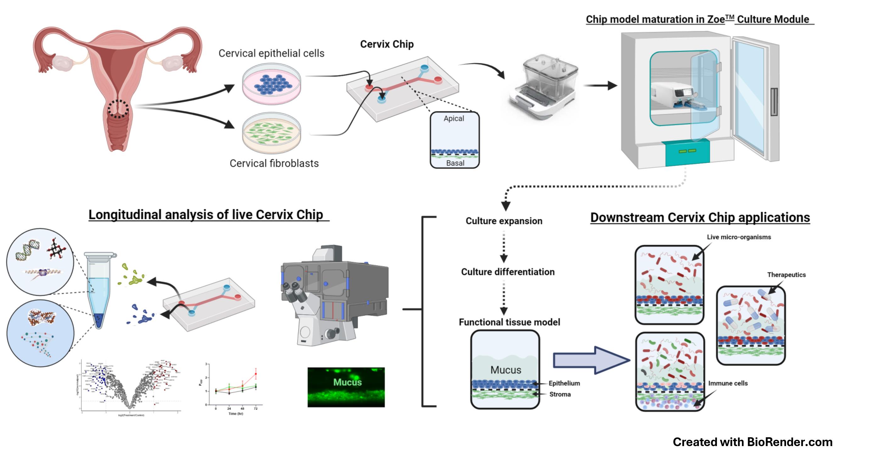
Human Cervix Chip design, culture, analysis, and applications
Background
The human cervix is a specialized mucosal organ that provides protection against external pathogens while supporting fertilization and fetal development in the female reproductive tract. Yet, little is known about its physiology and pathophysiology. In fact, progress in the broader area of female reproductive and sexual health has lagged behind other fields, and this is largely due to persistent knowledge gaps and a lack of concerted efforts in both basic and translational research. The scarcity of new, more effective therapeutics for female diseases affects approximately one-third of women globally, placing a significant economic burden on healthcare systems [1]. Studying the physiology and pathophysiology of the female reproductive tract ex vivo has been challenging due to the complexity of these organs and their microenvironment, as well as the limitations of conventional animal studies, tissue explants, and standard cell cultures. While these models are convenient, widely used, and standardized, they fail to faithfully replicate the structure, function, and physiological responses of the human female organs due to species differences or overly simplified configurations [2–5].
Microfluidic Organ-on-a-Chip (Organ Chip) technology provides a promising platform for developing in vitro models that mimic human physiology and disease states at the cellular, tissue, organ, and even organism levels [6–9]. We recently described the development of an Organ Chip model of the human cervix (Cervix Chip) [6] using a commercially available dual-channel microfluidic chip (Chip-S1, Emulate Inc., USA) and their ZoëTM culture module, which operates automatically inside a standard tissue culture incubator. The Chip-S1 is composed of two parallel microfluidic channels, each less than 1 mm wide, separated by an extracellular matrix (ECM)-coated microporous membrane. The Cervix Chip is created by lining one side of this membrane with human primary cervical epithelial (CE) cells, while primary human cervical stromal cells are cultured on the opposite side of the same membrane in the parallel channel (see Graphical overview). Both cell types are then expanded and differentiated under dynamic flow conditions to form a functional cervical epithelium and underlying stroma that closely resembles the epithelial–stromal interface of the cervical mucosa in vivo. The human Cervix Chip exhibits key features of the living cervix, including the formation of a functional tissue barrier, the accumulation of a thick mucus layer overlying the epithelium, and responsiveness to female hormones, environmental factors, and both healthy and dysbiotic microbiome. Additionally, the Cervix Chip protocol allows for continuous analysis of molecular, cellular, and functional properties, as well as endpoint analyses on fixed tissues. The transparent chip design enables noninvasive optical imaging, and the ability to control flow dynamics allows for stable co-cultures for days with live microorganisms (e.g., bacteria) as well as the collection of effluents from the epithelial and stromal channels individually for off-chip analysis (e.g., similar to sampling cervical discharge and blood or interstitial fluid, respectively).
Previous protocols for engineering 3D cervical tissues in vitro did not offer such versatility or the ability to conduct longitudinal studies without interrupting cultures [10]. Performing complex co-culture studies with multiple cell types or microorganisms has also been challenging in static culture models [11,12]. The Cervix Chip overcomes these limitations and provides a robust platform for investigating tissue dynamics and host–microbiome interactions. Importantly, because the Organ Chip devices and automated chip culture instruments we used are commercially available, this approach can be pursued in any lab able to acquire this equipment. The availability of mass-manufactured chips and control systems also enables high reproducibility and standardization, making it valuable for academic, clinical, and pharmaceutical applications.
The human Cervix Chip protocol described here has been previously validated in a study that successfully modeled bacterial vaginosis (BV) in vitro. BV is a chronic condition affecting over 25% of women, characterized by a shift in the vaginal microbiome from Lactobacillus crispatus dominance to a diverse community of anaerobic bacteria, including Gardnerella vaginalis and Atopobium vaginae [13–15]. This study showed that the Cervix Chip is a useful tool for studying complex disease conditions of the cervical mucosa, such as BV. We have also pursued a similar approach to create an Organ Chip of the human vagina [7]. This can be extended to create models of other organs of the female urogenital and reproductive tract (e.g., uterus, fallopian tube, ovary, urethra, and bladder).
Materials and reagents
Biological materials
1. Human cervical epithelial cells (LifeLine Cell Technology, catalog number: FC-0080)
2. Human cervical stromal cells, de-identified donor human hysterectomy or cadaver tissue obtained following approval by the Institutional Review Board of Wyss Institute for Biologically Inspired Engineering at Harvard University (Protocol number: IRB22632) and Mass General Brigham (Protocol number: 2015P001859)
Reagents
1. Trypsin 0.05%-EDTA 1× (Gibco, catalog number: 25300-054)
2. Defined trypsin inhibitor (DTI) (Thermo Fisher, catalog number: R007100)
3. Cervical cell culture basal medium (Lifeline Cell Technology, catalog number: LM-0055)
4. Cervical Cell Culture Growth kit; includes HLL supplement LifeFactor, HAS, linoleic acid, lecithin, rh insulin LifeFactor, rh EGF LifeFactor, L-glutamine LifeFactor, epinephrine LifeFactor, extract PTM LifeFactor, hydrocortisone hemisuccinate LifeFactor, triiodothyronine LifeFactor, and PS transferrin LifeFactor reagents (LifeLine Cell Technology, catalog number: LL-0072)
5. Fibroblast basal medium (ATCC, catalog number: PCS-201-030)
6. Fibroblast Growth kit, low serum; includes L-glutamine rh FGF basic, rh insulin, hydrocortisone, ascorbic acid, and FBS reagents (ATCC, catalog number: PCS-201-041)
7. Penicillin-streptomycin (Gibco, catalog number: 15070063)
8. Primocin (InvivoGen, catalog number: ant-pm-2)
9. Ascorbic acid (ATCC, catalog number: PCS-201-040)
10. Beta-estradiol (Sigma, catalog number: E8875)
11. Collagen I bovine (Advanced BioMatrix, catalog number: 5005-100ML)
12. Collagen IV, human placenta Col IV powder (Sigma-Aldrich, catalog number: C7521-10MG)
13. Fibronectin, human (Corning, catalog number: 356008)
14. Dispase (Worthington Biochemical Corporation, catalog number: LS02109)
15. Collagenase V (Sigma, catalog number: C-9263)
16. Acetic acid (Sigma-Aldrich, catalog number: A6283)
17. RPMI 1640 medium (Thermo Fisher Scientific, catalog number: 21875-034)
18. Advanced DMEM/F12 (Thermo Fisher Scientific, catalog number: 12634010)
19. Fetal bovine serum (FBS) (Thermo Fisher, catalog number: A3840001)
20. HBSS, pH 7.4 (Thermo Fisher, catalog number: 14025076)
21. DPBS (Thermo Fisher Scientific, catalog number: 14190144)
22. Calcium chloride (CaCl2) (anhyd.) (Thermo Fisher, catalog number: 423525000)
23. Magnesium chloride (MgCl2·6H2O) (Thermo Fisher, catalog number: 413415000)
24. Magnesium sulfate (MgSO4·7H2O) (Thermo Fisher, catalog number: 423905000)
25. Potassium chloride (KCl) (Thermo Fisher, catalog number: 424090250)
26. Potassium phosphate monobasic (KH2PO4) (Thermo Fisher, catalog number: 424205000)
27. Sodium chloride (NaCl) (Thermo Fisher, catalog number: 424295000)
28. ER-1TM (EmulateTM Inc., USA, catalog number: ER105)
29. ER-2TM (EmulateTM Inc., USA, catalog number: ER225)
30. Trypan blue solution (Sigma-Aldrich, catalog number: T8154-200ML)
31. Collagenase IV (Gibco, catalog number: 17104019)
32. TrypLE (Thermo Fisher, catalog number: 12605010)
33. N-acetylcysteine (NAC) (Sigma, catalog number: A9165)
34. 16% Paraformaldehyde (PFA) (Thermo Fisher Scientific, catalog number: 28908)
35. Cascade Blue® hydrazide, trilithium salt (Thermo Fisher, catalog number: C3239)
36. Fluorescent wheat germ agglutinin (WGA) (Invitrogen, catalog number: W11261)
37. Cell lysis buffer (QIAGEN, catalog number: 74034)
Solutions
1. Col IV stock solution (see Recipes)
2. Fibronectin stock solution (see Recipes)
3. Beta-estradiol stock solution (see Recipes)
4. 4% PFA solution (see Recipes)
5. HBSS [LB/-G] (see Recipes)
6. Cervical growth medium (see Recipes)
7. Fibroblast growth medium (see Recipes)
8. Cervical epithelium differentiation medium (see Recipes)
Recipes
Note: Prepare the growth media fresh every three days. Sterilize the HBSS [LB/-G] and growth media using the vacuum filtration system inside the biosafety cabinet before storage at 4 °C.
1. Col IV stock solution
| Reagent | Final concentration | Quantity or Volume |
|---|---|---|
| Collagen IV powder | 500 μg/mL | 10 mg |
| dH2O | n/a | 19.96 mL |
| Acetic acid | n/a | 40 μL |
| Total | n/a | 20 mL |
Filter sterilize the solution using a 0.2 μm filter. Store at -20 °C in small-volume aliquots to avoid freeze-thaw cycles.
2. Fibronectin stock solution
| Reagent | Final concentration | Quantity or Volume |
|---|---|---|
| Fibronectin | 100 μg/mL | 1 mg |
| DPBS | n/a | 10 mL |
| Total | n/a | 10 mL |
Make the solution under aseptic conditions. Store aliquots at -80 °C.
3. Beta-estradiol stock solution
| Reagent | Final concentration | Quantity or Volume |
|---|---|---|
| Beta-estradiol | 1 μg/mL | 1 mg |
| 100% ethanol | n/a | 1,000 mL |
| Total | n/a | 1,000 mL |
Store at -80 °C.
4. 4% PFA solution
| Reagent | Final concentration | Quantity or Volume |
|---|---|---|
| 16% PFA | 4% | 1 mL |
| DPBS | n/a | 3 mL |
| Total | n/a | 4 mL |
Make fresh solution before tissue fixation.
5. HBSS [LB/-G]
| Reagent | Final concentration | Quantity or Volume |
|---|---|---|
| CaCl2 | 140 mg/L | 140 mg |
| MgCl2·6H2O | 100 mg/L | 100 mg |
| MgSO4·7H2O | 100 mg/L | 100 mg |
| KCl | 400 mg/L | 400 mg |
| KH2PO4 | 60 mg/L | 60 mg |
| NaCl | 8 g/L | 8 g |
| H2O | n/a | 1,000 mL |
| Total | n/a | 1,000 mL |
6. Cervical growth medium
| Reagent | Final concentration | Quantity or Volume |
|---|---|---|
| Cervical cell culture basal medium | n/a | 474 mL |
| Cervical Cell Culture Growth kit | ||
| HLL supplement LifeFactor | 1.25 mL | |
| HSA | 500 μg/mL | |
| Linoleic acid | 0.6 μM | |
| Lecithin | 0.6 μg/mL | |
| rh Insulin LifeFactor | 5 μg/mL | 0.5 mL |
| rh EGF LifeFactor | 6 mM | 0.5 mL |
| L-glutamine LifeFactor | 1 μM | 15 mL |
| Epinephrine LifeFactor | 0.4% | 0.5 mL |
| Extract PTM LifeFactor | 100 ng/mL | 2 mL |
| Hydrocortisone hemisuccinate LifeFactor | 10 nM | 0.5 mL |
| Triiodothyronine LifeFactor | 5 μg/mL | 0.5 mL |
| PS Transferrin LifeFactor | 0.5 mL | |
| Penicillin-streptomycin | 50 U/mL | 5 mL |
| Total | n/a | 500 mL |
7. Fibroblast growth medium
| Reagent | Final concentration | Quantity or Volume |
|---|---|---|
| Fibroblast basal medium | n/a | 464 mL |
| Fibroblast Growth kit, low serum | ||
| L-glutamine | 7.5 mM | 18.75 mL |
| rh FGF basic | 5 ng/mL | 0.5 mL |
| rh Insulin | 5 μg/mL | 0.5 mL |
| Hydrocortisone | 1 μg/mL | 0.5 mL |
| Ascorbic acid | 50 μg/mL | 0.5 mL |
| FBS | 2% | 10 mL |
| Penicillin-streptomycin | 50 U/mL | 5 mL |
| Total | n/a | 500 mL |
8. Cervical epithelium differentiation medium
| Reagent | Final concentration | Quantity or Volume |
|---|---|---|
| Cervical growth medium | n/a | 490 mL |
| Beta-estradiol stock solution (-80 °C) | 5 nM | 0.5 mL |
| Ascorbic acid (50 mg/mL) | 50 μg/mL | 0.5 mL |
| Total | n/a | 500 mL |
Laboratory supplies
1. Basic Research Chip kit, 24 PK containing Chip-S1 and Pod® devices (Emulate Inc. USA) (Figure 1a)
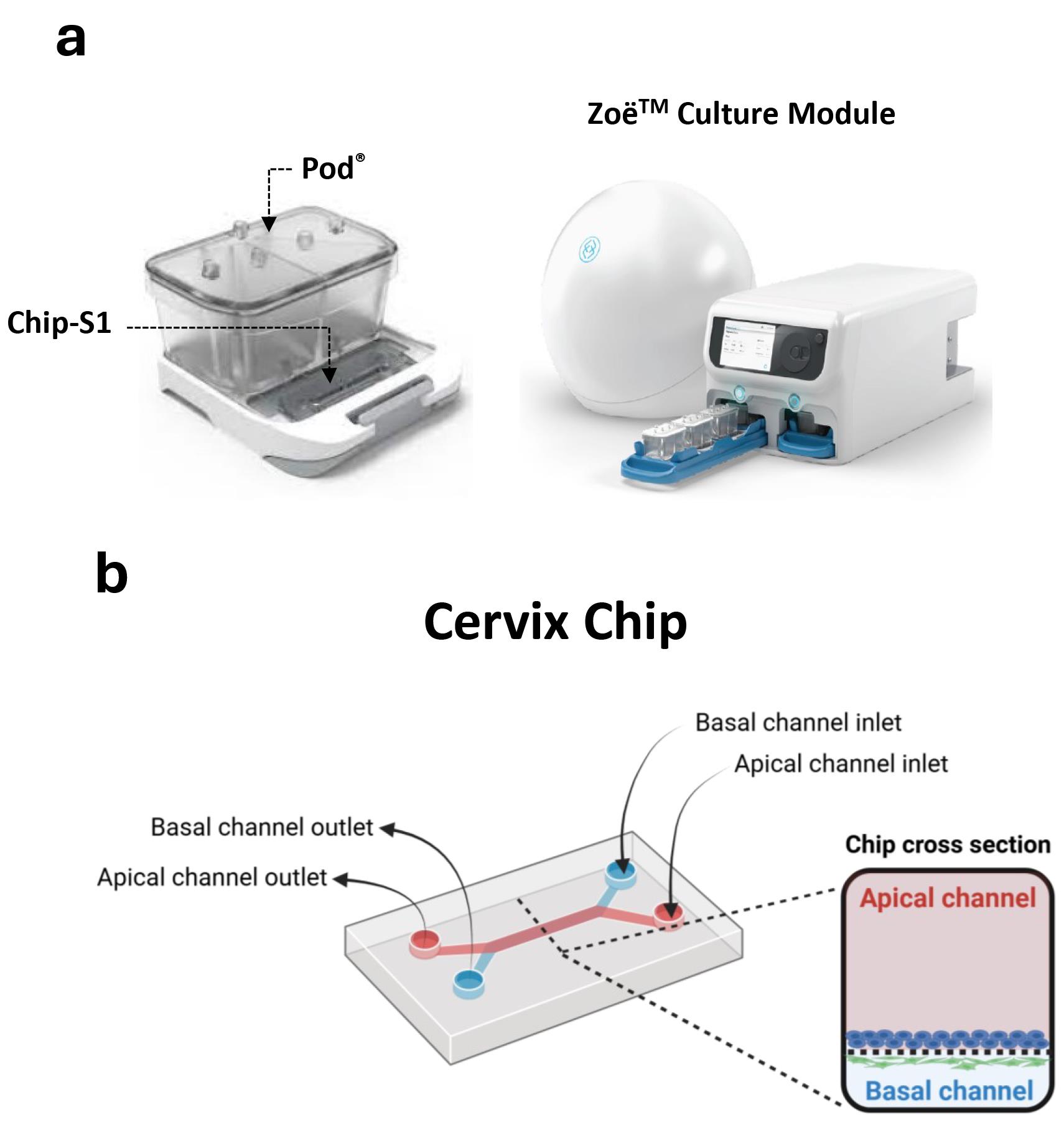
Figure 1. Commercial microfluidic chip device and automated culture module for creating the cervix chip. (a) Chip-S1 mounted on the microfluidic Pod® (left) for culture in ZoëTM culture module (right). (b) Schematic of the dual-channel cervix chip showing the inlets and outlets of the apical and basal channels as well as the cross-section view of the chip.
2. T75 flask (Thomas Scientific, catalog number: 21A00M452)
3. 35 mm cell culture dish (Corning, catalog number: 353001)
4. Conical centrifuge and microcentrifuge tubes
5. Hemocytometer
6. Steriflip vacuum filter units (Fisher Scientific, catalog number: SCGP00525)
7. Vacuum filtration system (Corning, catalog number: 431096)
8. Cell sieve (Corning, catalog number: 431752)
9. Square clear Petri dish (Thomas Scientific, catalog number: 688161)
10. 96-well assay block, 2 mL (Costar, catalog number: 04624000)
11. 96-well half area black flat bottom microplate (Corning, catalog number: 3881)
12. Disposable scalpel (VWR, catalog number: 76457-484)
13. Test tube rack (Thermo Fisher Scientific, catalog number: 5970-0120)
14. U-PLEX® Biomarker Assay kit (Mesoscale Discovery, catalog number: K15067L-1)
Equipment
1. Class II Biosafety cabinet (Thermo Fisher Scientific, model: 1300 Series A2)
2. Tissue culture incubator (VWR, model: Water Jacketed CO Incubator, catalog number: 10810-878)
3. ZoëTM culture module (Emulate Inc., model: CM-1) (Figure 1a)
4. Phase contrast/fluorescence microscope (Zeiss, model: Axio Observer Z1)
5. Condenser (Zeiss, model: 0.35 NA, 424241-0000-000)
6. Benchtop centrifuge (Eppendorf, model: 5804 R)
7. UV lamp (Nailstar, model: NS-01-US)
8. Multimode plate reader (BioTek NEO, model: Gen5 3.11)
9. MSD microplate reader (Mesoscale Discovery, model 1300 MESO QuickPlex SQ 120MM)
Software and datasets
1. Prism v8.1.2 (GraphPad Software Inc., San Diego, CA)
2. Fiji version v1.8 ( https://doi.org/10.1038/nmeth.2019)
3. Discovery Workbench v4.0.12
Procedure
Below, we provide a step-by-step procedure for creating the human Cervix Chip, starting with the 2D culture and expansion of primary human cervical cells, followed by their culture and differentiation in the commercially available Chip-S1 devices and ZoëTM Culture Module. This protocol utilizes primary human cervical epithelial (CE) cells sourced from Lifeline® Cell Technology LLC and primary cervical stromal cells isolated from clinical tissues (with Institutional Review Board review and approval), as there is currently no commercial supplier for cervical stromal cells. Using commercially available epithelial cells ensures reproducibility across experiments. Although primary epithelial cells can also be isolated from donor tissues, this protocol focuses on the method we validated using commercially sourced primary epithelial cells.
Before proceeding, the ZoëTM Culture Module must be purchased from Emulate Inc., installed in a tissue culture incubator, and verified for stable operation to ensure successful implementation of the protocol.
A. 2D culture and expansion of primary cells
1. Expansion of commercial CE cells in 2D culture
a. Place the cell cryovial in a 37 °C water bath and gently rock back and forth until a piece of ice is left in the vial (approximately 30 s to 1 min).
b. Add 1 mL of the cervical growth medium to the vial and transfer to a 15 mL conical tube.
c. Top up the cell suspension with an additional 5 mL of growth medium.
d. Count the cells and their viability using a hemocytometer and trypan blue exclusion assay.
e. Plate the cells in T75 flasks at 250,000 cells/flask and incubate at 37 °C and 5% CO2 until the cells reach 60%–70% confluency (typically in 4–5 days).
f. Passage the cells by rinsing the flasks 1× with 5 mL of DPBS per each T75.
g. Aspirate DPBS and add 2 mL of Trypsin 0.05%-EDTA to each flask. Incubate at 37 °C for 2 min.
h. Remove from the incubator and tap the flasks gently 2–3 times to detach the cells.
i. Add 5 mL of DTI to each flask and collect the cells in a 15 mL conical centrifuge tube.
j. Centrifuge at 150× g for 5 min at room temperature and resuspend the cell pellet in cervical growth medium.
k. Count the cells using a hemocytometer and trypan blue exclusion assay.
l. Plate the cells at 250,000 cells/T75 flask.
m. Culture the CEs until 60%–70% confluency is reached and ready for chip culture seeding.
2. Isolation and culture of cervical fibroblasts (CFs) (adopted from [16])
a. Cut the stromal tissue from the cervix clinical sample and transfer to a 35 mm cell culture dish.
b. Cut the tissue into small pieces using a disposable scalpel.
c. Enzymatically digest the minced tissue in 1.25 U/mL dispase and 0.4 mg/mL collagenase V in RPMI 1640 medium containing 10% FBS with gentle shaking at 37 °C for 30–60 min.
d. Pass the digest through a 100 μm cell sieve and collect the flowthrough.
e. Add 10 mL of fibroblast growth medium to stop the digestion.
f. Centrifuge at 250× g for 5 min and resuspend the cell pellet in 3 mL of fibroblast growth medium.
g. Count the cells and plate at 250,000 cells per T75.
h. Pass the CFs following the same procedure as in steps A1f–l.
B. Cervix Chip activation
This activation process enhances the chip membrane’s hydrophilicity and binding to other materials (e.g., ECM) through polydimethylsiloxane (PDMS) surface oxidization.
1. Bring the ER-1TM and ER-2TM components (the commercial surface activation reagents) to the biosafety cabinet to equilibrate at room temperature for 10–15 min.
2. Bring the UV lamp device inside the biosafety cabinet.
3. Spray the Chip-S1 packages with 70% ethanol, place them inside the biosafety cabinet, and remove from the packaging.
4. Turn off the biosafety cabinet lights and wrap a 15 mL conical tube with aluminum foil.
5. Add 1 mL of ER-2TM to the ER-1TM bottle and gently pipette up and down the mixture. Transfer the reconstituted solution to the 15 mL tube and repeat this step three more times.
Note: Repeated washes with ER-2TM ensure that the ER-1TM powder is completely dissolved and transferred from the original bottle with minimum loss.
6. Add 6 mL of ER-2TM to the 4 mL reconstituted ER-1TM in the conical tube to a total of 10 mL of 0.5 mg/mL ER-1TM solution. Mix gently without creating bubbles.
7. Take 100 μL of the ER-1TM solution and carefully introduce approximately 20–40 μL solution through the basal channel inlet (Figure 1b), pipetting until the solution begins to exit the channel outlet (Video 1).

8. Move the pipette containing the remaining ER-1TM solution to the apical channel inlet and introduce approximately 50–60 μL of ER-1TM solution to the top channel inlet (Figure 1b), pipetting until the solution begins to exit the top channel outlet (Video 1).
9. Remove the pipette tip and gently aspirate any excess ER-1TM solution from the surface of the chip.
10. Ensure there are no bubbles in the chip channels. If any bubble exists, dislodge it by washing the channel with ER-1TM solution until all bubbles have been removed (see General Note 1).
11. Place the chips containing ER-1TM in a clear Petri dish without the lid and place it into the UV box (Video 1).
Critical: If the lid is not removed prior to placing the dish in the UV box, the chips will not activate properly and could result in poor cell attachment.
12. Turn on the UV light for 10 min.
13. Remove the chips from the UV box and fully aspirate the ER-1TM solution from all channels.
14. Refill the basal and apical channels with fresh ER-1TM following steps B7–10.
15. Place the chips back in the UV box and activate for an additional 5 min.
16. Remove the chips from the UV device and check the ER-1TM solution color in the chips for a dark red color (Video 1).
Pause point: If the color does not turn deep red, place the chips back in the UV box and illuminate with UV light for another 10 min. Change of color in the activation solution ensures that the nitrophenyl azide group of the photosensitive ER-1TM crosslinker is converted into a reactive nitrene group that can react with PDMS to create a high-affinity surface for binding with amines of ECM proteins.
17. Turn on the light in the biosafety cabinet and remove the chips from the UV box.
18. Fully aspirate the ER-1TM solution from both channels.
19. Wash each channel with 200 μL of ER-2TM and fully aspirate the channels.
20. Wash each channel with 200 μL of sterile cold DPBS.
21. Leave cold DPBS in the channels until ready to proceed with chip coating, typically within 10–15 min.
Note: Although keeping the activated PDMS surface in DPBS at a low temperature can prolong its hydrophilic state to a few hours, the surface binding capacity decreases with time; as such, this is not suggested.
C. Cervix Chip ECM coating
The choice of ECM coating in this protocol is based on the primary constituents of the basal lamina layer in the epithelium–stroma interface in the human cervix in vivo.
1. Prepare the extracellular matrix (ECM) coating solutions.
a. Thaw collagen IV and fibronectin on ice and keep collagen I solution on ice during the whole ECM coating preparation process.
b. Prepare basal coating solution by mixing collagen I (200 μg/mL) with fibronectin (30 μg/mL) in cold DPBS.
c. Prepare apical coating solution by thawing collagen IV (500 μg/mL) on ice.
Critical: Keep the prepared ECM solutions on ice throughout the coating process, as higher temperatures can initiate polymerization in the ECM solution before it is added to the chip.
2. Fully aspirate the cold DPBS from the channels.
3. Place and leave an empty P200 tip in the outlet of the basal channel, place the loaded tip in the inlet, and carefully add 50 μL of the basal coating solutions to the basal channel. Gently remove the pipette to leave the P200 loading tip in the apical inlet.
4. Place and leave an empty P200 tip in the apical channel outlet and carefully add 100 μL of the apical coating solution to the top channel through its inlet. Gently remove the P200 loading tip in the apical inlet.
5. Inspect the chip to make sure there are no bubbles in the channels.
Critical: If you detect bubbles, repeat loading the channels with the coating solution until the bubbles are removed. The presence of bubbles in the chip during incubation will result in non-coated areas on the membrane to which cells will not attach during seeding steps.
6. Incubate the loaded chips at 37 °C overnight to allow for polymerization of the ECM coating solution.
7. Next day, gently wash both channels with 200 μL of warm growth media and keep in media in the 37 °C incubator until ready for cell seeding.
D. Cervix Chip cell seeding
1. Seed CFs in Chip-S1 (Day -1).
a. Collect and count the CFs expanded in 2D culture at passage 5 [P5] following steps A1f–l.
b. Make the cell suspension at a concentration of 0.6–0.7×10⁶ cells/mL.
c. Add 100 μL of warm fibroblast growth medium to the apical channel while closing the outlet with an empty p200 tip and gently add the media leaving the loading tip in the inlet.
d. Gently pipette up and down the cell suspension and take 100 μL using a P200 tip.
e. Gently add the cell suspension into the basal channel and close the outlet with a P200 tip after approximately 20 μL of the medium has been released from the channel, leaving the loading tip in the inlet (see General Note 2).
f. After seeding the first chip, check under the brightfield microscope to make sure cells are present on the basal side and are uniformly distributed.
g. Quickly invert the chip upside down with attached P200 tips and rest the edges of the chip on empty openings of a test tube rack (Figure 2a).
Critical: Ensure the chips are completely leveled and have no tilted angle to avoid nonuniform CF attachment.
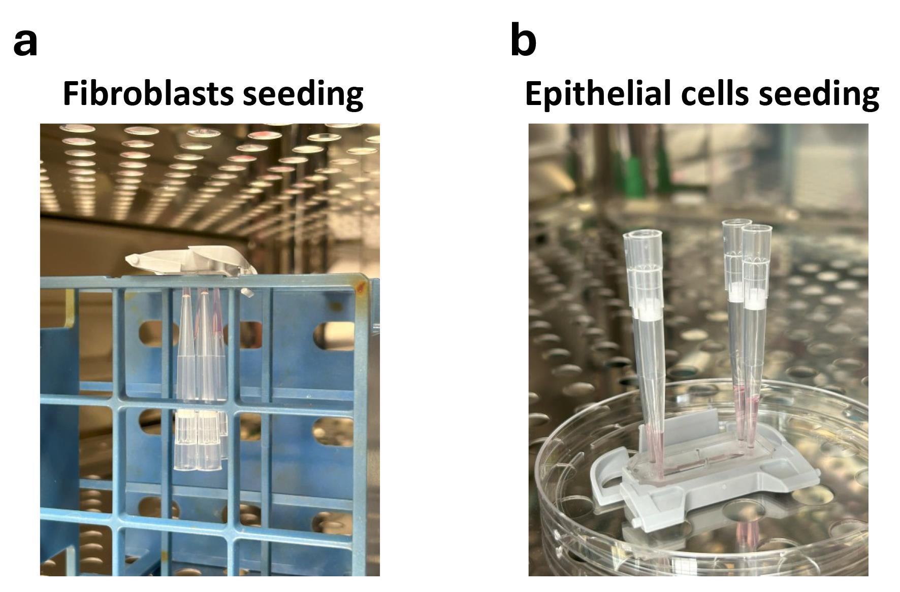
Figure 2. Fibroblasts and epithelial cells seeding on Cervix Chip. Images of the chip in (a) upside down position after stromal fibroblast seeding and (b) upright position after epithelial cell seeding during incubation for cell attachment in the bottom and top surfaces of the chip porous membrane, respectively.
h. Continue with seeding the rest of the chips with CFs.
i. Incubate the chips in an upside-down position in the 37 °C incubator for 2 h (Figure 2a).
j. After the incubation time, flip the chips to an upside position and gently wash the basal and apical channels with warm fibroblast growth medium.
k. Leave 50 μL of fibroblast growth medium in the basal and apical sides and close the outlets with a P200 tip.
l. Incubate the chips in the incubator at 37 °C and 5% CO2 overnight.
2. Seed CEs in Chip-S1 (Day 0).
a. Collect and count the CEs expanded in 2D culture at passage 5 [P5] following steps A1f–l.
b. Refresh the basal channel medium with 200 μL of warm fibroblast medium. Leave the P200 tips in the basal outlets.
c. Wash the apical side of the chip with 200 μL of warm cervical growth medium.
d. Make CE cell suspension at 1.5 × 10⁶ cells/mL.
e. Gently pipette the suspension up and down and take 100 μL of cell suspension in a P200 tip.
Critical: Gently mix the cell suspension before seeding each chip as the cells can settle in the suspension solution resulting in nonuniform cell densities across multiple chips.
f. Gently add the cell suspension into the apical channel.
g. After at least 50 μL of media has been released from the apical outlet, close the outlet with an empty P200 tip and leave the loading tip in the inlet (see General Note 2).
h. Check under the microscope to make sure cells are present and uniformly distributed in the apical channel.
i. Incubate the chips in the incubator at 37 °C and 5% CO2 overnight (Figure 2b).
E. Setting up Cervix Chip in ZoëTM culture module (Day 1)
1. Early in the morning, wash the chips with 200 μL of fresh cervical epithelial and fibroblast growth media apically and basally, respectively.
2. Add 200 μL of each media to the epithelial and stromal lumens, leaving the P200 tips, and keep in the 37 °C incubator until ready for connecting to Pods®.
Note: The Pod® is the commercially designed portable media reservoir that holds the microfluidic chip and supplies culture media through the automated ZoëTM culture module. It also enables easier handling of the Cervix Chip for microscopy under aseptic conditions.
3. Degas 50 mL of each growth media (see General Note 3).
4. Spray packaged Pods® with 70% ethanol and transfer into the biosafety cabinet.
5. Remove Pods® from the packaging and place them in the ZoëTM tray in the designated slots. Add 1,000 μL of growth media in the Pods® inlet reservoirs and 500 μL in the outlet reservoirs (Video 2).
6. Place the Pods® inside the ZoëTM culture module and run the Prime Cycle twice.
7. Take out the tray and check the microfluidic outlets of the Pod® to ensure liquid droplets have formed on the four outlets.
Pause point: If the droplets have not formed, repeat the Prime Cycle again until you see the formation of droplets. The absence of these droplets may indicate the presence of bubbles in the Pod® microfluidics that can lead to fluid flow blockage and bubble formation in the chip.
8. Take out the seeded chips from the incubator, remove the P200 tips, and add 50 μL of CE and CF growth media to the apical and basal channels, respectively, ensuring no bubble is in the channels or at the outlets.
Note: Leaving ~20 μL of media at the inlets and outlets of the chip will help to have no air traps in the microfluidics when connecting the chip to the Pod® (Video 2).
9. Gently connect the chip by sliding the Chip-S1 inside the grooved area of Pods® until you hear a click sound (Video 2).
10. Aspirate any remaining fluid on top of the chips (Video 2).
11. Top up the apical and basal inlet reservoirs of Pods® by adding 3.5 mL of growth media and aspirate any remaining media in the outlet reservoirs of Pod®.
12. Place the chips in the tray and insert it inside the ZoëTM culture module in the incubator.
13. Set the ZoëTM settings to Fluid in both top and bottom channels, with 30 μL/h apical and 40 μL/h basal flow rates, and stretch parameters to 0% strain and 0 Hz frequency.
Note: We do not use ZoëTM cyclic strain function on the Cervix Chip culture as the cervix mucosa does not experience continuous micromechanical deformation in vivo.
14. Start the RegulateTM Cycle in the ZoëTM.
F. Expansion of primary cells in Cervix Chip (Day 2–5)
1. On Day 2 of culture, press the activation button to stop the flow and adjust the flow rate setting to 0 μL/h apically and 40 μL/h basally (see General Note 4).
2. Start the flow by pressing the activation button.
3. Every 20 h, set the apical flow to 30 μL/h and culture the chips for 4 h using both apical and basal flow (basal flow at 40 μL/h).
4. After 4 h, set the apical flow back to 0 μL/h and maintain the basal flow rate at 40 μL/h.
5. Repeat this regimen of intermittent flow every day for the rest of the Cervix Chip culture (see General Note 5).
Note: This intermittent flow is adopted to mimic the recurrent flow of cervical discharge as seen in vivo with minimum shear stress, which promotes physiological differentiation of cervical epithelium on-chip.
G. Differentiation of primary cells in Cervix Chip (Day 5–12)
1. Prepare the cervical epithelium differentiation medium and HBSS solution (see General Note 3).
Day 5
2. Remove the growth media from the apical and basal reservoirs.
3. Add 3.5 mL of HBSS (pH 7.4) and 3.5 mL of cervical differentiation medium apically and basally, respectively, into the Pod® reservoirs.
4. Put the chips back into the ZoëTM and set the flow rate to 30 μL/h apically and 40 μL/h basally. Set the stretch parameters to 0% strain and 0 Hz frequency.
5. Start the RegulateTM Cycle in the ZoëTM.
6. The next day, set the apical flow to 0 μL/h and basal flow to 40 μL/h for 20 h.
7. Resume the intermittent flow regimen for the rest of the differentiation culture time following steps F3–5 (see General Note 6).
Day 7
8. Replace the HBSS (pH 7.4) in the Pods® apical reservoir with HBSS [LB/-G] (pH 5.4).
9. Continue the intermittent flow regimen until Day 14 of culture.
Day 12
10. The Cervix Chip is ready for endpoint analysis or further disease modeling (i.e., co-culture with bacteria) and drug screening.
H. Monitoring tissue development in Cervix Chip during culture
Throughout the chip culture time in the ZoëTM instrument, the Cervix Chip can be frequently and noninvasively monitored using phase contrast or immunofluorescent microscopic imaging without interrupting the culture (Figure 3).
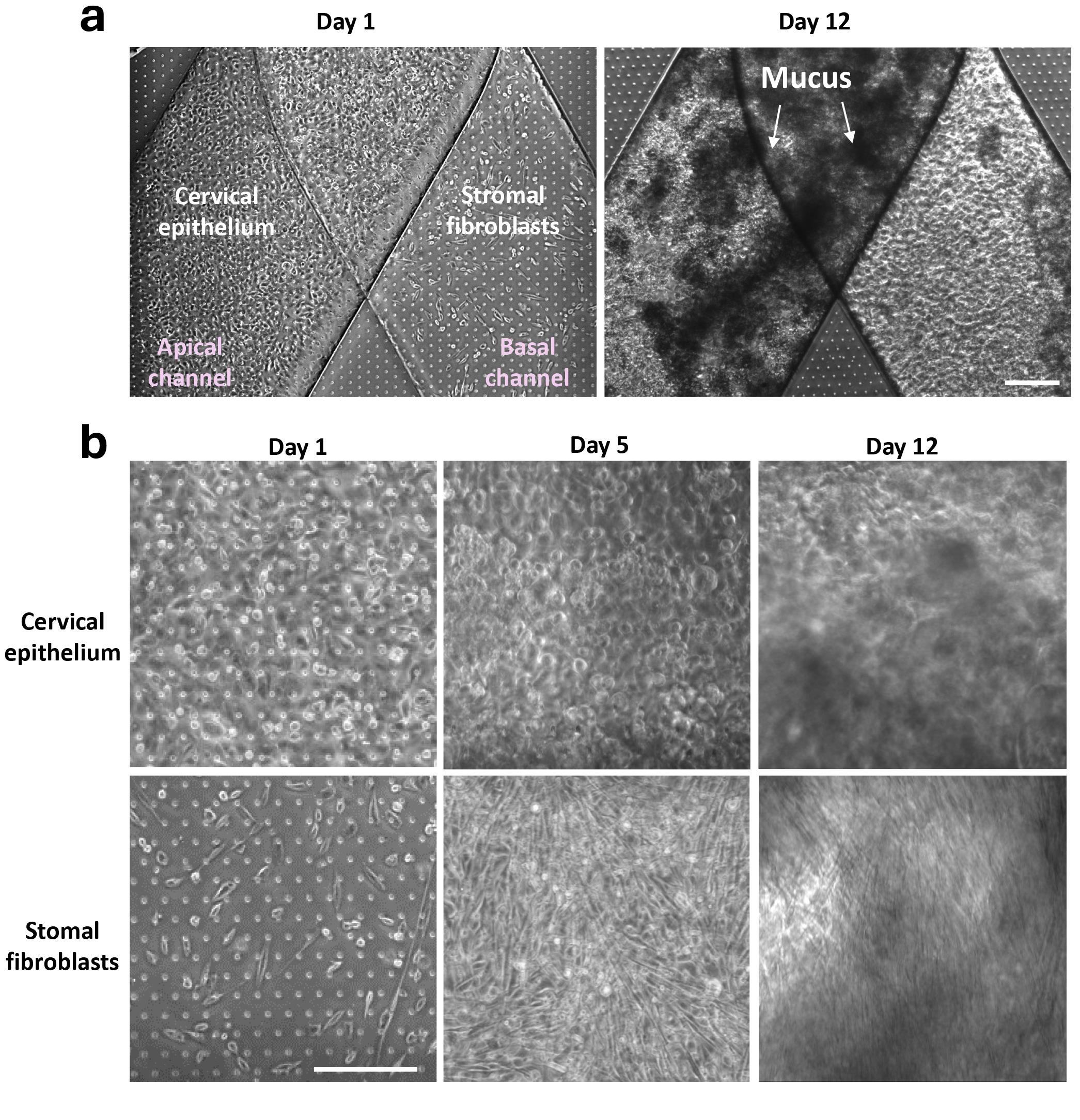
Figure 3. Development and microscopy imaging of 3D cervical epithelium–stromal tissue interface on Cervix Chip. (a) Phase contrast micrographs of Cervix Chip at Day 1 post cell seeding and Day 12 of culture (Day 7 of differentiation) showing the formation of dense cervical epithelium with secreted mucus in the apical lumen. Scale bar, 200 μm. (b) Higher magnification phase contrast images of epithelial (top row) and stromal fibroblast (bottom row) cells at multiple time points during the chip culture, demonstrating progressive formation of dense epithelium and stromal tissue layers on-chip after cell seeding (Day 1), expansion (Day 5), and differentiation (Day 12). Opaque substances on the epithelium surfaces in (A) and (B) represent secreted and accumulated mucus in the chip apical lumen. Scale bar, 200 μm.
1. Transfer the chip from the incubator to the microscope while attached to the Pods®.
2. Take phase contrast images of the epithelial and stromal cells in the apical and basal channels of the chip (see General Note 8).
3. Image the cells in representative areas along the length of the channel, for example, close to the inlets and outlets and an area in the middle of the chip, for both apical and basal sides (see General Note 9).
4. Perform phase contrast imaging to record the progress of tissue formation on-chip every 2–3 days.
I. Live mucus imaging in Cervix Chip
The mucus layer in the living Cervix Chip cultures can be continuously viewed noninvasively using either darkfield or fluorescent side-view microscopic imaging of the chip. This protocol is adopted from [17].
1. Chip preparation for side-view imaging (Figure 4a).
a. Transfer the chip with the attached Pod® to the biosafety cabinet and remove the chip from the Pod®.
b. Remove the PDMS chip from the plastic cradle and cut 2 mm of the PDMS from each side of the chip using a sharp razor blade preferably secured in a press (Pause point: see General Note 10).
c. Close the inlets and outlets of the chips with P10 tips for aseptic transfer of the chip to the microscope and imaging.
d. Flip the chip on its side on a glass coverslip coated with sterile DPBS.
e. Add an additional layer of sterile DPBS on top of the chip and place a coverslip on top to create a sandwich of the chip in between the two coverslips (see General Note 11).
f. Place the chip in between the coverslips in the slide holder of the microscope stage for imaging (Figure 4a).
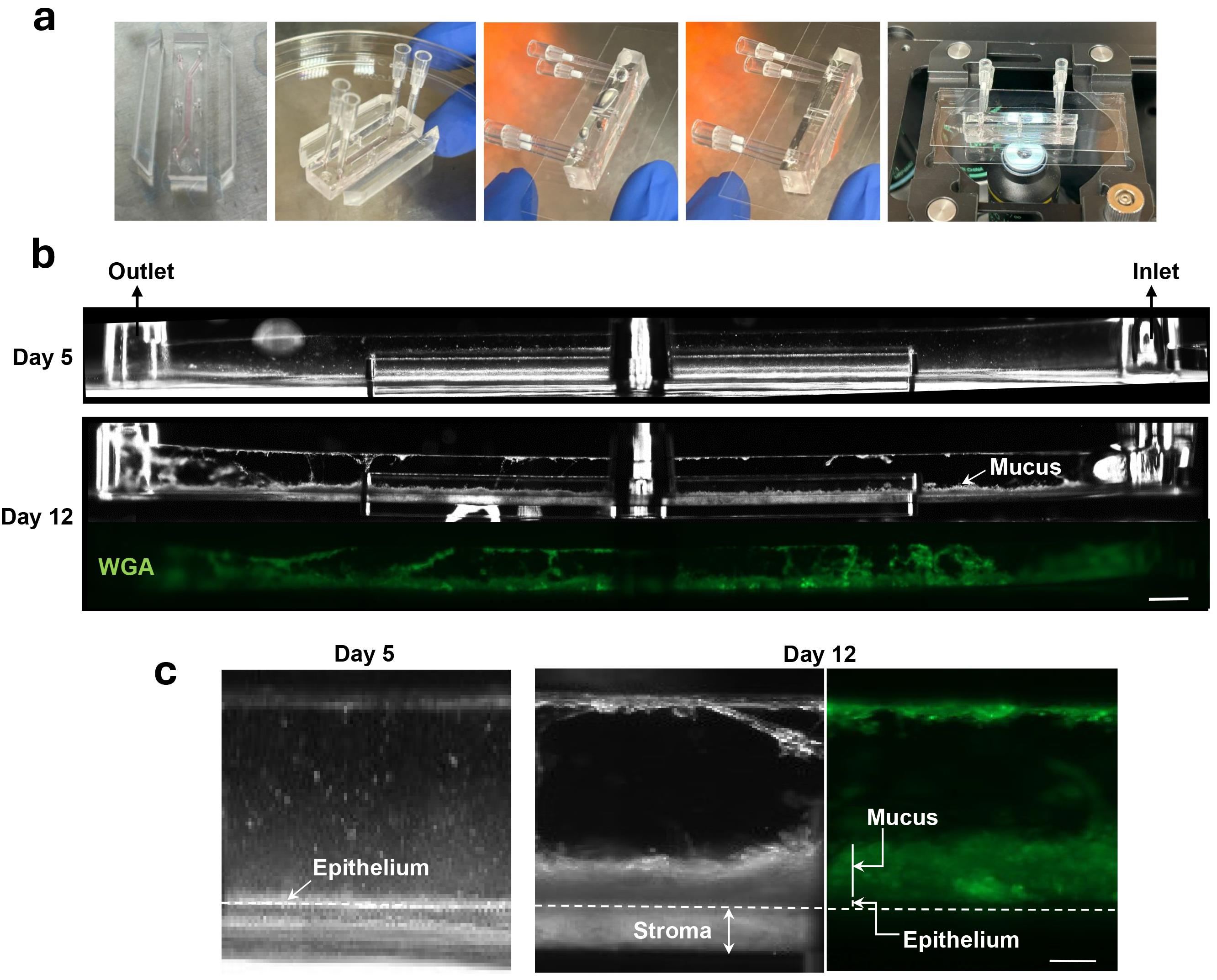
Figure 4. Side-view microscopic imaging of mucus layer in live Cervix Chip during culture. (a) Cervix Chip preparation steps for live side-view microscopy imaging (b). Darkfield (top and middle) and fluorescent wheat germ agglutinin (WGA)-stained (green, bottom) micrographs of live Cervix Chip at Days 5 and 12 of culture (Days 0 and 7 of differentiation, respectively) showing side views of Cervix Chip and the cervical mucus layer formed in the apical channel by time in culture. Scale bar, 1 mm. (c) Representative enlarged side-view micrographs of Cervix Chip showing a thin cervical cell layer before differentiation (Day 5 of expansion, left), and thick light-reflecting mucosal and stromal layers in the apical and basal channels (middle), as well as fluorescent WGA-labeled mucus layer (green, right) after 7 days of differentiation (Day 12 of culture). Scale bar, 200 μm.
2. Darkfield side-view imaging.
a. Attach the condenser to the microscope and set the objective to 2.5× or 5× with a Ph 2 phase ring.
b. Illuminate the chip and collect darkfield images.
Note: The epithelial and stromal tissues and the mucus layer appear as bright substances in the chip darkfield side-view images (Figure 4b).
3. Fluorescent wheat germ agglutinin (WGA) mucus side-view imaging.
a. Take the chips from the incubator to the biosafety cabinet and replace the HBSS [LB/-G] solution in the apical channel reservoir of the Pod® with 2 mL of 25 μg/mL WGA in HBSS [LB/-G].
b. Transfer the chips back into the ZoëTM and start the flow in the apical and basal channels at 30 μL/h apically and 40 μL/h basally for 2 h.
c. Replace the chips’ apical medium with fresh HBSS [LB/-G] and continue the flow for another 2 h to remove nonbonded WGA from the chip epithelium lumen.
d. After the wash time, transfer the chips back to the biosafety cabinet.
e. Remove the chips from the Pods® and prepare them for side-view fluorescent microscopy imaging following steps I1a–f.
f. Transfer the chip to the fluorescent microscope and collect side-view images (Figure 4).
4. Assemble the chip back together to continue culture in the ZoëTM.
a. Transfer the chip back to the biosafety cabinet and gently remove the P10 tips from the outlets.
b. Put back together the PDMS blocks that were cut from both sides of the chip and recreate the original configuration of the chip.
c. Place the assembled chip back in the plastic cradle.
Note: Make sure the chip perfectly fits inside the cradle and no significant shift has occurred in the inlet and outlet positions compared to the original position. This is to ensure the flow will resume smoothly in the chip after connecting to the Pod®.
d. Prime the Pod® in ZoëTM using the Prime Cycle and gently add ~20 μL of media to all chip outlets. Ensure there are no bubbles in the chip or at the outlets.
Note: Do not pipette media in the epithelium lumen of the chip, as this can disturb the intact mucus layer.
e. Gently connect the chip to the Pod® and transfer it into the ZoëTM to resume the culture.
5. Quantitative analysis of the mucus layer in the side-view images, including measuring the mucus layer thickness, total mucus area, and the fluorescent signal intensity, can be performed on collected images using standard image processing tools available in Fiji Software.
J. Off-chip effluent analysis
Chip effluents from the apical and basal channels can be collected continuously and used for a range of “off-chip” analyses, such as barrier function and cytokine analysis (Figure 5), as well as proteomics and metabolomics
chip effluent collection.
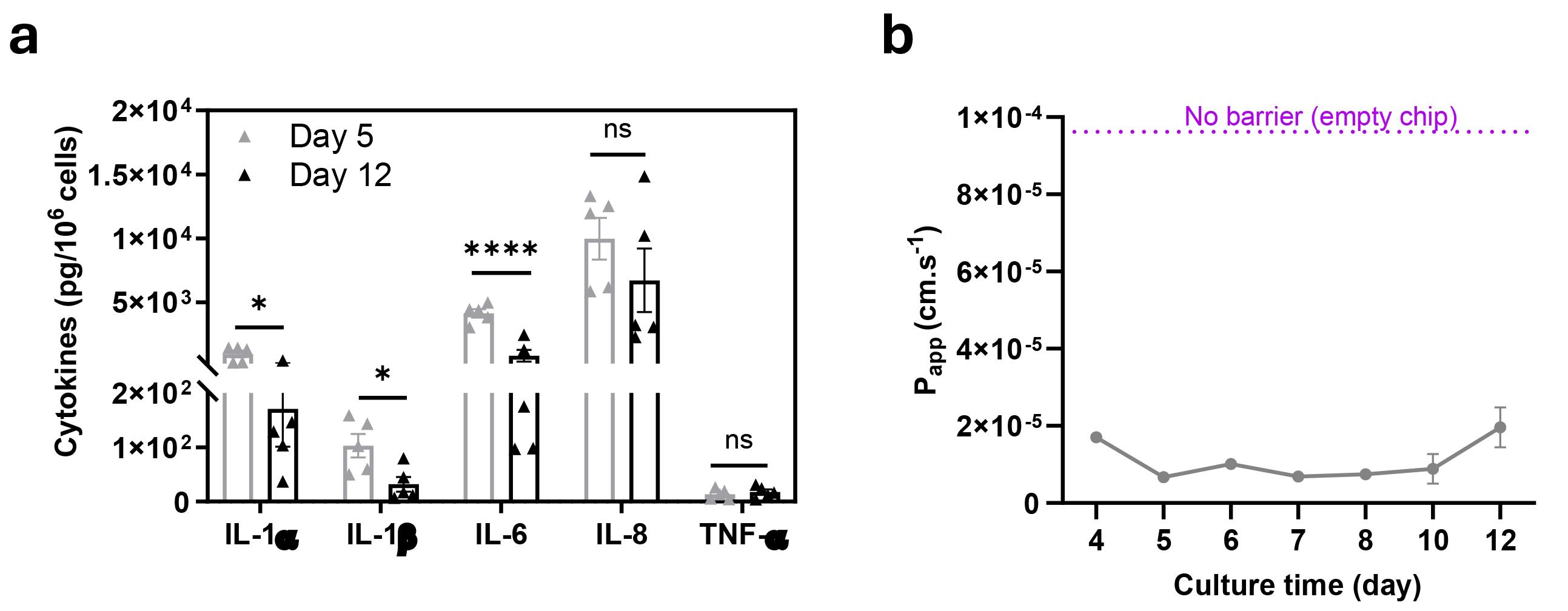
Figure 5. Analysis of innate immune responses and barrier function in live Cervix Chip during culture time. (a) Measurement of cytokine and chemokine protein levels in Cervix Chip epithelium lumen effluents before and after differentiation analyzed using a custom MSD U-PLEX® Biomarker Assay kit. (b) Continued measurement of barrier function in Cervix Chip during culture time using tracer dye permeability assay presented as apparent permeability (Papp). Data represents the mean ± s.e.m.; n=3 experimental chip replicates. Significance was calculated by unpaired Student’s t-test; * P ≤ 0.05, **** P≤0.0001.
1. Transfer the chips from the ZoëTM to the biosafety cabinet.
2. Aspirate all the basal and apical effluents in the Pods® from the overnight or previous days of flow.
3. Put the chips back in the ZoëTM and run the flow at 30 μL/h apically and 40 μL/h basally for 4 h.
4. Label a 96-deep-well assay plate for collecting the effluents of each outflow channel of all chips.
5. For each chip, measure and record the volume of the apical and basal effluents using a P1000 pipette.
a. Set the pipette volume to 200 μL.
b. Collect all the accumulated effluent with a P1000 tip and gently turn the central volume-adjusting rings in the pipette counterclockwise to decrease the volume to gently push the air out of the tip.
c. Once all extra air is out and only the collected effluent remains in the tip, take note of the volume shown on the pipette indicator display (see General Note 12).
d. Transfer the collected chip effluent to the allocated well in the 96-deep-well plate.
6. Store the effluents in a -80 °C freezer for downstream analysis.
Tracer dye barrier function assay:
7. Twenty-four hours prior to performing the assay, add Cascade Blue tracer dye in the apical channel inlet reservoir of the Pod® at 50 μg/mL in HBSS.
8. Perfuse the chips using the ZoëTM at 30 μL/h apically and 40 μL/h basally for 4 h.
9. Continue the chip culture at 0 μL/h apically and 40 μL/h basally for 20 h.
10. The next day, aspirate the apical and basal channel effluents and run flow on-chips at 30 μL/h apically and 40 μL/h basally for 4 h.
11. Repeat steps J4–5.
12. Take 40 μL of apical and basal effluents in three technical replicates in a 96-well microplate for each chip.
13. Make fresh Cascade Blue standards in a 96-deep-well block plate following the serial dilution technique (Table 1).
14. Add Cascade Blue standard in three technical replicates in the 96-well microplate.
15. Read the microplate within 15–20 min of collecting the samples at 390 nm/420 nm wavelength on the multimode plate reader.
Note: If the plates cannot be read immediately, store the plate at -80 °C to read later.
Table 1. List of Cascade Blue assay standards and their compositions
| Cascade Blue concentration (μg/mL) | Composition |
|---|---|
| 200 | 10 μL of 10 mg/mL Cascade Blue +490 μL of HBSS |
| 100 | 250 μL of (200 μg/mL) + 250 μL of HBSS |
| 50 | 250 μL of (100 μg/mL) + 250 μL of HBSS |
| 25 | 250 μL of (50 μg/mL) + 250 μL of HBSS |
| 12.5 | 250 μL of (25 μg/mL) + 250 μL of HBSS |
| 6.25 | 250 μL of (12.5 μg/mL) + 250 μL of HBSS |
| 3.125 | 500 μL HBSS |
K. End-point analysis
1. Mucus collection for off-chip mucin quantification and molecular analysis.
a. Transfer the chips from the ZoëTM to the biosafety cabinet.
b. Remove the chips from the Pods®.
c. Close off the basal channel outlets by inserting empty P200 tips in the inlet and outlet ports.
d. Put an empty P200 tip in the apical channel outlet.
e. Add 50 μL of 20 mM NAC in DPBS in the epithelium channel and leave the loading tip in the apical inlet.
f. Incubate the chip at 37 °C and 5% CO2 for 3 h.
g. Remove the chips from the incubator and connect the pipette plunger to the P200 tip in the apical channel inlet.
h. Gently pipette up and down the content 2–3 times.
i. Collect the mucus in the P200 tip and transfer to a labeled microcentrifuge tube.
j. Freeze immediately at -80 °C for downstream analysis.
2. Measure epithelium and stromal cell count and viability.
a. Close the apical channel outlet with an empty P200 tip and add 100 μL of prewarmed 1 mg/mL collagenase IV in TrypLE to the apical channel, leaving the loading tip in the inlet.
b. Repeat the previous step for the basal channel for collecting the stromal cells simultaneously.
c. Incubate the chips at 37 °C and 5% CO2 for 1.5–2 h.
d. Remove the chips from the incubator.
e. Attach the pipette plunger to the apical channel P200 tip in the inlet.
f. Gently pipette up and down the apical channel digestion solution (1 mg/mL collagenase IV in TrypLE) 2–3 times to detach the cells from the chip membrane.
g. Transfer the content into a 2 mL microcentrifuge tube.
h. Wash the apical channel with another 100 μL of the digestion solution.
i. Add 600 μL of differentiation medium to the cell digestion medium to stop the digestion enzyme.
j. Count the cells and calculate viability using the trypan blue exclusion assay.
k. Repeat steps K2e-j for the basal channel to collect and count cell viability in the stromal lumen of the Cervix Chip.
3. Cervix Chip sample collection for PCR and RNA-seq analysis.
a. Repeat steps K1a–c.
b. Close the apical channel outlet with a P200 tip and add 100 μL of cell lysis buffer to the apical channel.
c. Push the reagent through the channel and pipette up and down the lysis solution 3–4 times.
d. Collect the lysate solution in a microcentrifuge tube.
e. Inspect the chips under the microscope to ensure all cells have been lysed.
Note: If you observe any cells remaining in the channels, repeat steps K3c–d until no cells remain in the channel.
f. Repeat steps K3b–e for the basal stromal channel of the chip.
g. Briefly vortex the microcentrifuge tubes and store immediately at -80 °C.
4. Chip fixation and immunofluorescence staining.
a. Remove the chips from the Pods®.
b. Take 100 μL of DPBS in P200 tips and insert in the apical and basal channel inlets.
c. Release the pipette plunger to leave the tips in the inlets and allow gravity flow of DPBS to wash the epithelium and stromal channels.
d. Insert empty P200 tips in the outlets of apical and basal channels.
e. Repeat steps K4b–c to perfuse fresh 4% PFA in the apical and basal channels.
f. Leave the chips at room temperature in the biosafety cabinet for 20–30 min.
g. Wash the chips twice with DPBS following steps K4b–c.
h. Proceed with staining the chips using a standard immunofluorescent staining method or store the chips at 4 °C with at least 200 μL of DPBS in P200 tips in the chips inlet and outlet ports to prevent chips from drying out.
Data analysis
Qualitative and quantitative microscopy image analysis are performed using Fiji Software version V1.8 and its standard image analysis tools. In each chip experiment, at least three individual chips are used as experimental replicates for the designed groups. Statistical analysis is performed using GraphPad Prism version 8.1.2, and the statistical significances between groups are tested using two-tailed Student’s t-test or one-way ANOVA with Bonferroni correction for multiple hypothesis testing. Chip conditions including the cell phenotype and morphology and effluent levels should be monitored frequently during the culture; chips that show compromised morphology and phenotype should be closely monitored and excluded from data analysis if identified as outliers.
A detailed description of methods for calculating barrier function using tracer dye assay and cytokine and chemokine concentrations is provided in sufficient detail in the method section of our previous publication [6] or the user manual of the MSD Biomarker Assay kit.
Validation of protocol
This protocol or parts of it has been used and validated in the following research article:
Izadifar et al [6]. Mucus production, host-microbiome interactions, hormone sensitivity, and innate immune responses modeled in human cervix chips. Nature Commun.
Representative data demonstrating the robustness of the protocol are provided in Figures 3–5 in this protocol and in Figures 1–5 as well as Supplementary Figures 1, 2, and 5 in the original research article [6].
General notes and troubleshooting
General notes
1. Bubbles can be formed and persist in the channels when liquid is perfused in the chip. If this happens, aspirate the channel dry and slowly reintroduce the solution.
2. Introducing cold media to the chip can increase the chance of bubble formation during pipetting. Observe the chip for the possibility of bubble formation and remove any bubbles. Keep the cell suspension out of ice during seeding but perform seeding quickly.
3. Degas all culture media and solutions that will be used in the Chip-S1 Pod® reservoirs. Attach the 50 mL conical tube containing the medium or solution to the 0.2 or 0.4 µm Steriflip unit. Connect the filter outlet to the vacuum inside the biosafety cabinet. Leave the Steriflip unit upright for 30 s and then flip it upside down to filter the medium. Leave the unit under vacuum for at least 15 min before using the medium.
4. To promote the formation of cervical epithelium with more ectocervical-like phenotypes from the mixed commercial cell source, set the flow to 40 μL/h in both the apical and basal channels for a continuous flow regimen during the expansion time.
5. Top up the epithelial and stromal media in Pod® reservoirs and aspirate the chip effluents from Pod® outlet chambers every 2–3 days.
6. The same intermittent flow regimen is used during the differentiation time for both endocervical- and ectocervical-like Cervix Chips.
7. Throughout the chip culture in ZoëTM, check the chips frequently (every 12–24 h during the first 3–4 days, when the chips are more prone to bubble formation compared to later times of culture) to inspect for any bubble formation in the channels. This can be performed by grossly inspecting the chip channels for the presence of large bubbles or by inspection under a brightfield microscope for smaller bubbles. If observed, remove the chips from the Pods®, wash apical and basal channels gently with their media, perform the Prime Cycle following steps E6–8, connect the chip to the Pod®, and resume the culture inside ZoëTM. If bubbles are not removed, it can interfere with the normal media flow through the channels, potentially leading to cell death in the chip.
8. When performing chip microscopic imaging, use the porous membrane as a guide for identifying the apical and basal surfaces of the membrane for imaging the cell layer in each lumen.
9. If your microscope does not provide an environmental chamber to maintain physiological conditions (37 °C) during imaging, perform the imaging quickly to prevent compromising cell physiological conditions on-chip.
10. Make sure the PDMS cuts on each side of the chip are smooth (no groove marks) and exactly at 90°. Slant cuts can result in strong artifact light reflection in darkfield imaging. Additionally, hold onto the PDMS blocks cut from the sides of each chip to assemble them back together after finishing the imaging. The chips will be connected to the Pod® again to continue the culture in ZoëTM.
11. When performing side-view imaging, ensure the chip is immersed in DPBS on both sides (Figure 4a) for increased resolution and enhanced contrast against the dark background in the image.
12. Exact volume measurements are important for quantitative analysis of detected biomolecules in the chip effluents and their normalization across multiple chips and experiments.
13. Whenever bubbles appear in the chips during culture, transfer the chip with the attached Pod® to the biosafety cabinet. Detach the chip from the Pod®. Wash the apical and basal lumens of the chip with warm media to remove bubbles. Leave ~20 μL of media on the inlets and outlets of the chip. Place the Pods® in the ZoëTM tray and make sure there is at least 500 μL of media in all four reservoirs of the Pod. Put the Pod® back in the ZoëTM and run the Prime Cycle at least twice to create liquid droplets on the four outlets of the Pod®. Transfer the Pod® back into the biosafety cabinet and connect it to the chip. Resume the culture in ZoëTM.
Troubleshooting
Problem 1: Bubble formation in the chip channels.
Possible causes: Pre-existing microbubbles, missing the RegulateTM Cycle step before starting the culture, not degassing the media, or letting the chips run on very low media in the Pod® reservoirs can lead to chambers drying out overnight or during the weekend.
Solutions:
Make sure there are no bubbles in the chip channels during the activation and ECM-coating steps.
Make sure to start the chip culture with the RegulateTM Cycle in the ZoëTM and when you completely replace the media in the Pod® reservoirs.
Always degas media and solutions and prewarm them in the water bath or incubator before adding to the Pods®.
Top up the media in the Pods® before the media reaches less than 500 μL.
During the first 2–3 days of chip culture in ZoëTM, the risk of bubble formation is higher. Inspect the chips frequently to remove any formed bubbles (see General Note 13).
Problem 2: Reduced effluent volume in the basal channel with time in culture.
Possible cause: Overgrowth of the stromal fibroblasts and gradual clogging of the flow stream in the basal channel.
Solution: Optimize your primary stromal fibroblast seeding density to a lower level to extend the growth time before they overgrow and negatively influence the flow in the basal channel.
Acknowledgments
We thank the other members of our laboratory who assisted in past studies validating this technology and acknowledge research funding from Bill and Melinda Gates Foundation (INV-035977 to D.E.I.), Canada’s Natural Science and Engineering Research Council (NSERC) (to Z.I.), and the Wyss Institute for Biologically Inspired Engineering at Harvard University (to D.E.I.). The original research paper in which this protocol was described and validated is by Izadifar et al [6].
Competing interests
D.E.I. holds equity in Emulate, chairs its scientific advisory board, and is a member of its board of directors. Z.I. declares no competing interests.
Ethical considerations
All methods were carried out in accordance with the approval of the Institutional Review Board of Wyss Institute for Biologically Inspired Engineering at Harvard University (Protocol number IRB22632) and Mass General Brigham (Protocol number 2015P001859). When human research participants were involved, informed consent was not obtained because the samples were deidentified. No compensation was provided to the participants.
References
- Mercuri, N. D. and Cox, B. J. (2022). The need for more research into reproductive health and disease. eLife. 11. https://doi.org/10.7554/eLife.75061.
- Eade, C. R., Diaz, C., Wood, M. P., Anastos, K., Patterson, B. K., Gupta, P., Cole, A. L. and Cole, A. M. (2012). Identification and characterization of bacterial vaginosis-associated pathogens using a comprehensive cervical-vaginal epithelial coculture assay. PLoS One. 7(11): e50106. https://doi.org/10.1371/journal.pone.0050106
- Xiao, S., Coppeta, J. R., Rogers, H. B., Isenberg, B. C., Zhu, J., Olalekan, S. A., McKinnon, K. E., Dokic, D., Rashedi, A. S., Haisenleder, D. J., et al. (2017). A microfluidic culture model of the human reproductive tract and 28-day menstrual cycle. Nat Commun. 8: 14584–14584. https://doi.org/10.1038/ncomms14584.
- Edwards, V. L., Smith, S. B., McComb, E. J., Tamarelle, J., Ma, B., Humphrys, M. S., Gajer, P., Gwilliam, K., Schaefer, A. M., Lai, S. K., et al. (2019). The Cervicovaginal Microbiota-Host Interaction Modulates Chlamydia trachomatis Infection. mBio. 10(4). https://doi.org/10.1128/mbio.01548-19.
- Pavlidis, I., Spiller, O. B., Sammut Demarco, G., MacPherson, H., Howie, S. E. M., Norman, J. E. and Stock, S. J. (2020). Cervical epithelial damage promotes Ureaplasma parvum ascending infection, intrauterine inflammation and preterm birth induction in mice. Nat Commun. 11(1): 199. https://doi.org/10.1038/s41467-019-14089-y.
- Izadifar, Z., Cotton, J., Chen, S., Horvath, V., Stejskalova, A., Gulati, A., LoGrande, N. T., Budnik, B., Shahriar, S., Doherty, E. R., et al. (2024). Mucus production, host-microbiome interactions, hormone sensitivity, and innate immune responses modeled in human cervix chips. Nat Commun. 15(1): 4578. https://doi.org/10.1038/s41467-024-48910-0.
- Mahajan, G., Doherty, E., To, T., Sutherland, A., Grant, J., Junaid, A., Gulati, A., LoGrande, N., Izadifar, Z., Timilsina, S. S., et al. (2022). Vaginal microbiome-host interactions modeled in a human vagina-on-a-chip. Microbiome. 10(1): 201. https://doi.org/10.1186/s40168-022-01400-1.
- Plebani, R., Potla, R., Soong, M., Bai, H., Izadifar, Z., Jiang, A., Travis, R. N., Belgur, C., Dinis, A., Cartwright, M. J., et al. (2021). Modeling pulmonary cystic fibrosis in a human lung airway-on-a-chip. J Cyst Fibros. 21(4):606–615. https://doi.org/10.1016/j.jcf.2021.10.004.
- Ingber, D. E. (2022). Human organs-on-chips for disease modelling, drug development and personalized medicine. Nat Rev Genet. 23: 467–491. https://doi.org/10.1038/s41576-022-00466-9.
- Arslan, S. Y., Yu, Y., Burdette, J. E., Pavone, M. E., Hope, T. J., Woodruff, T. K. and Kim, J. J. (2015). Novel three dimensional human endocervix cultures respond to 28-day hormone treatment. Endocrinology. 156(4): 1602–1609. https://doi.org/10.1210/en.2014-1840.
- Barrila, J., Radtke, A. L., Crabbé, A., Sarker, S. F., Herbst-Kralovetz, M. M., Ott, C. M. and Nickerson, C. A. (2010). Organotypic 3D cell culture models: using the rotating wall vessel to study host–pathogen interactions. Nat Rev Microbiol. 8(11): 791–801. https://doi.org/10.1038/nrmicro2423
- Łaniewski, P. and Herbst-Kralovetz, M. M. (2021). Bacterial vaginosis and health-associated bacteria modulate the immunometabolic landscape in 3D model of human cervix. NPJ Biofilms Microbiomes. 7(1): 88. https://doi.org/10.1038/s41522-021-00259-8.
- Ravel, J., Brotman, R. M., Gajer, P., Ma, B., Nandy, M., Fadrosh, D. W., Sakamoto, J., Koenig, S. S., Fu, L., Zhou, X., et al. (2013). Daily temporal dynamics of vaginal microbiota before, during and after episodes of bacterial vaginosis. Microbiome. 1(1): 29. https://doi.org/10.1186/2049-2618-1-29.
- Peebles, K., Velloza, J., Balkus, J. E., McClelland, R. S. and Barnabas, R. V. (2019). High Global Burden and Costs of Bacterial Vaginosis: A Systematic Review and Meta-Analysis. Sex Transm Dis. 46(5): 304–311. https://doi.org/10.1097/olq.0000000000000972.
- Ravel, J., Gajer, P., Abdo, Z., Schneider, G. M., Koenig, S. S., McCulle, S. L., Karlebach, S., Gorle, R., Russell, J., Tacket, C. O., et al. (2011). Vaginal microbiome of reproductive-age women. Proc Natl Acad Sci USA. 108 Suppl 1: 4680–4687. https://doi.org/10.1073/pnas.1002611107.
- Turco, M. Y., Gardner, L., Hughes, J., Cindrova-Davies, T., Gomez, M. J., Farrell, L., Hollinshead, M., Marsh, S. G. E., Brosens, J. J., Critchley, H. O., et al. (2017). Long-term, hormone-responsive organoid cultures of human endometrium in a chemically defined medium. Nat Cell Biol. 19(5): 568–577. https://doi.org/10.1038/ncb3516.
- Sontheimer-Phelps, A., Chou, D. B., Tovaglieri, A., Ferrante, T. C., Duckworth, T., Fadel, C., Frismantas, V., Sutherland, A. D., Jalili-Firoozinezhad, S., Kasendra, M., et al. (2020). Human Colon-on-a-Chip Enables Continuous In Vitro Analysis of Colon Mucus Layer Accumulation and Physiology. Cell Mol Gastroenterol Hepatol. 9(3): 507–526. https://doi.org/10.1016/j.jcmgh.2019.11.008.
Article Information
Publication history
Received: Dec 18, 2024
Accepted: Mar 2, 2025
Available online: Mar 18, 2025
Published: Apr 5, 2025
Copyright
© 2025 The Author(s); This is an open access article under the CC BY-NC license (https://creativecommons.org/licenses/by-nc/4.0/).
How to cite
Izadifar, Z. and Ingber, D. E. (2025). A Human Cervix Chip for Preclinical Studies of Female Reproductive Biology. Bio-protocol 15(7): e5262. DOI: 10.21769/BioProtoc.5262.
Category
Biological Engineering > Synthetic biology
Cell Biology > Tissue analysis > Tissue culture
Cell Biology > Cell isolation and culture > Microfluidic culture
Do you have any questions about this protocol?
Post your question to gather feedback from the community. We will also invite the authors of this article to respond.