- Protocols

- Articles and Issues
- For Authors
- About
- Become a Reviewer

A Novel and Robust Method for Investigating Fungal Biofilm
Published: Vol 15, Iss 1, Jan 5, 2025 DOI: 10.21769/BioProtoc.5146 Views: 1784
Reviewed by: Lucy XieSascha BrunkeSimab KanwalShailesh Kumar
Original research article
The authors used this protocol in:
Aug 2023
Advertisement


Protocol Collections
Comprehensive collections of detailed, peer-reviewed protocols focusing on specific topics


Abstract
Candida auris, labeled an urgent threat by the CDC, shows significant resilience to treatments and disinfectants via biofilm formation, complicating treatment/disease management. The inconsistencies in biofilm architecture observed across studies hinder the understanding of its role in pathogenesis. Our novel in vitro technique cultivates C. auris biofilms on gelatin-coated coverslips, reliably producing multilayer biofilms with extracellular polymeric substances (EPS). This method, applicable to other Candida species like C. glabrata and C. albicans, is cost-effective and mimics the niche of biofilm formation. It is suitable for high-throughput drug screening and repurposing efforts, aiding in the development of new therapeutics. Our technique represents a significant advancement in Candida biofilm research, addressing the need for consistent, reproducible biofilm models. We detail a step-by-step procedure for creating a substratum for biofilm growth and measuring biofilm thickness using confocal laser scanning microscopy (CLSM) and ultrastructure by scanning electron microscopy (SEM). This method provides consistent outcomes across various Candida species.
Key features
• The biofilm formed on gelatin surfaces mimics host conditions, replicating the multilayered structure and EPS, offering a more accurate model for studying C. auris biofilms.
• This method is highly reproducible and suitable for drug screening and biofilm analysis through three-dimensional (3D) reconstruction.
• This in vitro technique aids in studying biofilm formation, related virulence properties, and drug tolerance of C. auris and other Candida species.
• The simple, cost-effective technique is ideal for screening novel inhibitors and repurposed drug libraries, facilitating the design/identification of new therapeutics against Candida species.
Keywords: Candida albicansGraphical overview
Background
Candidiasis is a serious threat, especially to individuals with compromised immune systems and comorbidities. Hospitalized patients, particularly those who have undergone organ or bone marrow transplants or are receiving immune-suppressive therapies, are highly susceptible to infections [1]. Prolonged hospital stays further increase the risk of contracting hospital-acquired infections [2]. A critical concern is the emergence of Candida auris, a fungal pathogen first isolated in 2009 [3]. Since then, C. auris has become a global health concern, with reports of drug resistance emerging from as many as 32 countries, particularly during the COVID-19 pandemic among hospitalized patients [4]. C. auris as a drug-resistant nosocomial pathogen has a reported mortality rate of 30%–50% in infected persons [5]. This pathogen can cause various infections, including ear, systemic (fungemia), wound, lung, urinary tract, and gut infections [5–7]. Due to its high resistance to various antifungal treatments and its potential for pan-drug resistance, the World Health Organization (WHO) has listed C. auris in the critical priority group of fungal pathogen priority list (FPPL) released in October 2022 [8].
Unlike other Candida species, C. auris seldom colonizes the gut but can persist on the skin by forming resilient biofilms, which causes rapid spread of this fungus in hospitals [9]. C. auris demonstrates remarkable resilience, especially in its biofilm form, which shows substantial resistance [10]. According to the Centers for Disease Control and Prevention (CDC), C. auris biofilms are resistant to common disinfectants, including ammonium salt–based solutions, and can endure harsh conditions [11]. C. auris can persist in the cutaneous layer by dividing and forming biofilms, which can cause bloodstream infection when they reach the blood vessels [12]. This underscores the necessity of studying biofilm formation in infection scenarios to develop effective treatments. Given the widespread drug resistance, there is an urgent need for robust screening platforms to identify novel inhibitors. Drug repurposing must be validated through rigorous in vitro and in vivo screening methods. However, a major challenge is establishing a reliable method to form biofilm models that accurately replicate in vivo conditions. The phenotypes of C. auris biofilms can vary significantly based on culture conditions, complicating research outcomes. Current methods, such as those using Thermanox (polystyrene) coverslips or porcine skin surfaces [13,14], either fail to produce typical biofilm architecture or lack cost-effectiveness for large-scale screenings. A standard surface for biofilm proliferation is crucial for reproducibility, as effective drug screening requires the typical multilayered architecture of biofilms.
To address these issues, we proposed a novel in vitro method for growing C. auris biofilms on gelatin-coated coverslips derived from bovine skin. Gelatin, a derivative of collagen, mimics the matrix of mammalian cells, thereby more closely replicating natural conditions. This method successfully forms heterogeneous, multilayered biofilms of C. auris. The architecture of these biofilms has been analyzed using scanning electron microscopy (SEM) and compared with previous studies [14–16]. Furthermore, the versatility and accuracy of this method have been demonstrated using confocal scanning laser microscopy (CSLM) to measure biofilm thickness. The application of this innovative in vitro technique is not only limited to C. auris biofilms but can also be used to study biofilm formation in other Candida species, such as Candida glabrata and Candida albicans. This method is a potent, cost-effective solution for large-scale drug screenings.
Here, we describe a stepwise procedure for creating a substratum for biofilm growth and measuring biofilm thickness with confocal laser scanning microscopy and ultrastructures by scanning electron microscopy. As mentioned above, it results in reliable outcomes and is suitable for various Candida species with different media. This method has been successfully used in previously published studies, demonstrating its effectiveness and reliability [15,16].
Materials and reagents
Biological materials
1. Candida auris strain of clade 2, CBS10913T
Reagents
1. Gelatin derived from bovine skin and bones (Sigma-Aldrich, catalog number: G9391-100G)
2. Double-distilled water
3. BD Difco YPD broth (Fisher Scientific, catalog number: DF0428-17-5)
4. 0.3 N hydrochloric acid (HCl) (Fisher Scientific, catalog number: 7647-01-0)
5. 100% ethanol (G-Bioscience, catalog number: RC1533)
6. 3-aminopropyl triethoxysilane (Himedia, catalog number: RM6592-100G)
7. Acetone HPLC grade (MERCK, catalog number: 60002010001730)
8. Glutaraldehyde 25%, w/w (Himedia, catalog number: MB222-100ML)
9. RPMI-1640 w/ or w/o MOPS and with L-glutamate added (Himedia, catalog number: AL028G-500ML)
10. Calcofluor white (CFW) (Sigma-Aldrich, catalog number: 18909-100ML-F)
11. Paraformaldehyde (Sigma-Aldrich, catalog number: F8775-500ML)
12. Alcian blue (Himedia, catalog number: RM471-25G)
13. Sodium cacodylate trihydrate (Himedia, catalog number: RM3732-25G)
14. Sodium chloride (NaCl) (Himedia, catalog number: MB023-1KG)
15. Potassium chloride (KCl) (G Biosciences, catalog number: RC1167)
16. Sodium phosphate dibasic anhydrous (Na2HPO4) (SRL, catalog number: 53046)
17. Potassium phosphate monobasic (KH2PO4) (G Biosciences, catalog number: RC1173)
18. Transparent nail paint
Solutions
1. YPD broth (see Recipes)
2. 1× PBS (see Recipes)
3. Scanning electron microscopy (SEM) buffer (see Recipes)
4. Other solutions (see Recipes)
Recipes
1. YPD broth (1 L)
Add 50 g of Difco YPD broth to 1 L of distilled water and sterilize by autoclaving at 121 °C for 20 min before use.
2. 1× PBS (1 L)
To prepare 1× PBS, weigh the components mentioned in the table below and dissolve in 500 mL of water. Once all the components are dissolved, make up the volume to 1 L and autoclave.
| Reagent | Amount |
|---|---|
| NaCl | 8 g |
| KCl | 0.2 g |
| Na2HPO4 | 1.44 g |
| KH2PO4 | 0.24 g |
| Double-distilled water (ddH2O) | to 1 L |
3. Scanning electron microscopy (SEM) buffer (50 mL)
To prepare the SEM buffer, add the following chemicals and make up the volume to 50 mL. Filter with pore size 0.22 μm, sterilize, and store at -20 °C.
| Reagent | Stock concentration | Amount | Final concentration |
|---|---|---|---|
| Alcian blue | n/a | 75 mg | 0.15% |
| Sodium cacodylate | n/a | 1.2 g | 0.15 M |
| Glutaraldehyde | 25% | 4 mL | 2% |
| Paraformaldehyde | 37% | 2.7 mL | 2% |
| Double distilled water (ddH2O) | n/a | To 50 mL | n/a |
| Total | 50 mL |
4. Other solutions
| Reagents | Stock concentration | Amount | Final concentration |
|---|---|---|---|
| CFW | 1 mg/mL | 30 μL | 30 μg/mL in 1 mL |
| HCl | 12 N | 2.5 mL | 0.3 N in 100 mL |
| 3-aminopropyl triethoxysilane | n/a | 1 mL | 2% in 50 mL |
| Gelatin | n/a | 1g | 1% in 100 mL |
| Ethanol | 100% | 2.5 mL (10 mL) | 25% |
| 100% | 5 mL (10 mL) | 50% | |
| 100% | 7 mL (10 mL) | 70% | |
| 100% | 8 mL (10 mL) | 80% | |
| 100% | 9.5 mL (10 mL) | 95% |
Laboratory supplies
1. 1.5 mL microcentrifuge tubes (Tarsons, catalog number: 500010)
2. 15 mL conical bottom tubes (Tarsons, catalog number: 430766)
3. 50 mL conical bottom tubes (Tarsons, catalog number: 430829)
4. 1,000 μL tips (Tarsons, catalog number: 521020B)
5. 200 μL tips (Tarsons, catalog number: 521010Y)
6. Conical flasks (Borosil catalog number: 4980021)
7. 90 mm Petri dishes (Tarsons, catalog number: 460095)
8. 24-well polystyrene plates (Thermo Scientific, catalog number: 142475)
9. 6-well polystyrene plates (Thermo Scientific, catalog number: 140675)
10. Kimwipes (Fisher Scientific, catalog number: 34120)
11. Glass slides (any high-quality glass slides)
12. Glass coverslips (any high-quality glass coverslips)
13. Carbon tape (TED PELLA, Inc., product no.: 16084-1)
Equipment
1. Eppendorf New Brunswick InnovaTM 42/42 R, stackable incubator shaker (Fisher Scientific, catalog number: 05-400-162)
2. Heat block (DTH-100 Dry bath incubator)
3. Vortex (BR Biochem, catalog number: BI-VM-2500)
4. Refrigerated benchtop centrifuge 5910 R (Eppendorf, catalog number: 5942000130)
5. Centrifuge 5427 R (Eppendorf, catalog number: 5429000133)
6. Light microscope (Leica, model: Sp5)
7. Scanning electron microscope (Apreo VolumeScope FEI)
8. Airstream® class II type A2 biological safety cabinet
9. Spectrophotometer Gene Quant 1300 (VWR, catalog number: SCLI80-2120-02)
10. Vacuum desiccator (Sigma-Aldrich, catalog number: Z119024)
11. Quorum SC7620 sputter coater
12. Hot-air oven (Scientific Systems)
13. Digital orbital shaker (Heathrow Scientific, catalog number: 120460)
14. Forceps
15. Autoclave
16. Water bath (Grant instruments, model: SBB Aqua 5 plus)
Software and datasets
1. LAS-AF
2. FIJI 1.54
3. GraphPad Prism 9
4. Adobe Photoshop CC 2019
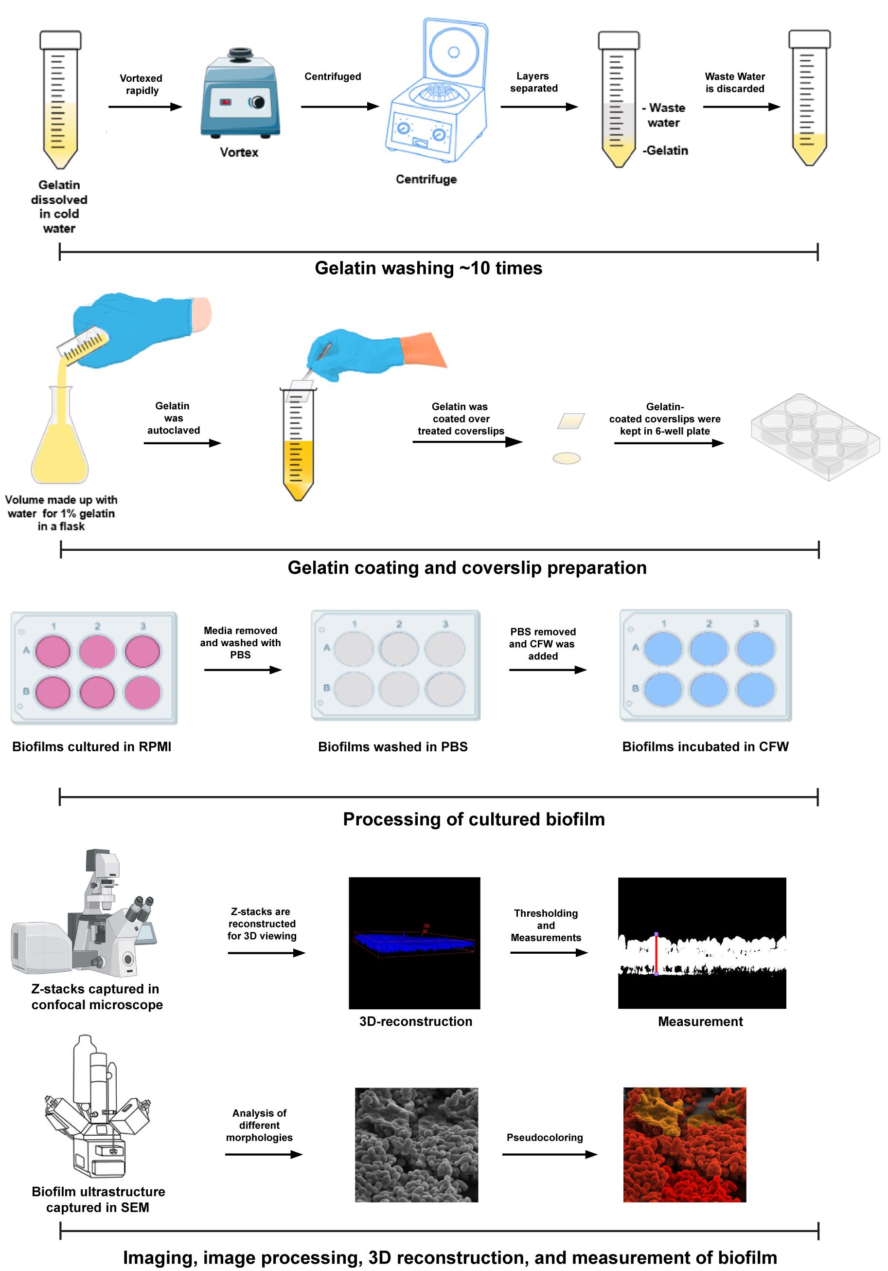
Procedure
A. Preparation of coverslips
1. Gelatin preparation
a. Dissolve 1 g of gelatin (bovine skin derived) in 25 mL of ice-cold distilled water.
b. Vortex the solution to remove any clumps.
c. Centrifuge the solution at 1,000× g for 10 min at 4 °C.
d. The pellet consists of gelatin, while the top water layer contains debris, dust specks, and other water-soluble impurities.
e. Repeat this step ~10 times or until the top water layer is transparent.
f. Finally, resuspend the washed gelatin in 100 mL of water to make 1% w/v suspension and autoclave.
g. Store the autoclaved gelatin at -20 °C in 50 mL conical bottom tubes. This can be stored for up to 6 months to a year.
h. To warm the gelatin again, incubate the gelatin-containing tubes in a 37 °C water bath.
2. Coverslip preparation
a. All steps must be done in a sterile environment.
b. Treat coverslips in a conical flask half filled with 0.3 N hydrochloric acid and frequently swirl overnight using an orbital shaker at 100 RPM to dissolve any contaminations and organic impurities.
c. Remove the acid and thoroughly wash the coverslips with 50 mL of autoclaved water three times.
d. Treat the coverslip with 100% ethanol for 30 min, with frequent swirling.
e. Discard the ethanol and dry the coverslips in a hot-air oven at 65 °C overnight in a sterile flask.
f. Prepare a 2% (3-aminopropyl) triethoxysilane solution in acetone. Dip each coverslip in the silane solution two times using forceps. This alkoxysilane treatment helps bridge the organic groups of gelatin to the silicon on the glass surface.
g. Dry the coverslips at room temperature and then wash them with water to remove excess unbound silane.
h. Dry the coverslips thoroughly in a hot air oven for 6–8 h.
i. Dip the alkoxysilane-treated coverslips in the previously prepared warmed gelatin solution to coat the surfaces.
j. Dry the coverslips at room temperature for 15 min.
k. Dip the coverslips one by one in glutaraldehyde solution in a 50 mL conical bottomed tube using forceps and leave them to dry at room temperature.
l. Repeat the gelatin coating and glutaraldehyde fixation step again.
m. After the coating dries up, dip the coverslips in water for washing and drying.
n. These coverslips can be stored at -20 °C for a year in Petri dishes between lint-free tissue stacks.
B. Biofilm formation and processing
1. Biofilm formation
a. Inoculate fungus cells in 5 mL of YPD medium in a 50 mL flask or 50 mL tube and incubate at 30 °C and 200 RPM overnight to establish a primary culture.
b. Use overnight-grown culture to prepare a secondary culture at ≤ 0.1 OD600 and incubate at 200 RPM in a shaker incubator at 30 °C until it reaches an OD600 between 0.6 and 0.8. Measure OD600 in a spectrophotometer.
c. Harvest cells by centrifugation at 3,500× g for 5 min, wash the cell pellet twice with 1× PBS, and resuspend in 1 mL of 1× PBS.
d. Prepare RPMI 1640 or RPMI-MOPS medium for biofilm formation. RPMI 1640 or RPMI-MOPS can be used to grow the biofilm; the only difference is in the buffering systems present in both media. RPMI 1640 contains sodium bicarbonate as a buffer to maintain the pH, whereas RPMI-MOPS [3-(N-morpholino) propanesulfonic acid] contains propane sultone buffer with a pH of 7.2, maintaining the physiological buffering conditions.
e. Place individually coated coverslips into the wells of 24-well plates and add 500 μL of the appropriate medium to each well.
f. Adjust the cell density to an OD600 of 0.5 before seeding them onto the coverslips.
g. Adjust 0.5 OD600 cells over the coverslips. Allow the cells to adhere by incubating them for 2.5–3 h in an incubator maintained at 37 °C.
h. When changing the medium, avoid disturbing adhered cells by gently adding the medium in drops along the wells’ walls. This marks the starting point (Time point 0) and any treatment regime can be designed relative to this time point.
i. Incubate the biofilm for 48 h undisturbed at 37 °C in a static incubator.
j. After incubation, harvest the coverslips for further processing. To harvest the biofilm, carefully remove the coverslips from the wells using forceps without shaking or disturbing them to prevent disrupting the formed biofilm.
2. Biofilm processing for confocal laser scanning microscopy (CLSM)
a. Wash the biofilm-containing coverslips with 500 μL of 1× PBS buffer by slowly aspiring the media from the wells by its meniscus using a 200 μL pipette, followed by adding 1× PBS in a continuous dropwise manner along the walls.
b. The biofilm forms on the upper side of the coverslips. The calcofluor-white (CFW) signal will be calculated from the bottommost signal layer to the topmost layer to measure the biofilm thickness.
c. Prepare calcofluor-white (CFW) stain solution at a working concentration of 30 μg/mL dissolved in 1× PBS.
d. Add enough CFW to submerge the biofilm-containing coverslips in the wells and incubate in the CFW solution at 30 °C for 30 min.
e. Transfer the coverslips onto glass slides in such a way that the side with the biofilm faces the glass.
f. Seal the coverslips over the glass slides with transparent nail paint to prevent drying before visualization under the confocal microscope.
3. Biofilm processing for scanning electron microscopy (SEM)
a. Treat the biofilm-containing coverslips with 0.15 M sodium cacodylate by submerging them in this solution for 5 min at room temperature in 24- or 6-well plates and then discarding the remaining liquid. If using 24-well plates, 500 μL of solution is required to fully submerge the coverslip. For 6-well plates, approximately 3 mL of solution is needed to immerse the coverslips. Repeat this step two times.
b. Keep the biofilm-containing coverslips in SEM buffer (2% paraformaldehyde, 2% glutaraldehyde, 0.15 M sodium cacodylate, and 0.15% alcian blue in water) and incubate overnight at 4 °C.
c. Transfer the coverslips to another 6-well plate and wash them twice with 0.15 M sodium cacodylate.
d. Different concentrations of ethanol, such as 25%, 50%, 80%, and 95%, are made using absolute ethanol and 0.15 M sodium cacodylate in separate conical-bottom tubes.
e. Slowly dehydrate the fixed biofilm-containing coverslips by sequentially exposing them to increasing concentrations of ethanol in gradient, gradually starting with 25% for 5 min followed by 50% for 10 min, 70% for 15 min, 80% for 15 min, 95% for 30 min, and at last with absolute ethanol for 1 h.
f. Vacuum dry the biofilm-containing coverslips overnight in a vacuum desiccator.
g. Dry the coverslips by submerging them in acetone for 3 h.
h. After dehydration, mount the coverslips on adhesive carbon tape with the biofilm side facing up.
i. Coat the coverslips with gold particles using an argon ion beam coater, maintaining a pressure of 0.08 mbar and voltage of 15 mV.
C. Acquisition of images
1. Image acquisition using Leica SP5
a. Configure LAS-AF software with a pixel size set to 2,048 × 2,048 and a scanning speed of 200 Hz.
b. Utilize a 20× objective lens for image capture.
c. Select focus planes ranging from the lowest focal plane displaying blue signals to the upper focal plane showing blue signals. Blue signals depict the CFW bound to chitin.
d. Set step sizes at 0.6 μm for Z-stacking.
e. Perform scanning starting from the nearest dark slice in the lowest layer to the nearest dark slice in the highest layer.
f. Use bidirectional scanning mode and maintain a pinhole size of 60 μm so that a single layer comes at each step (Figure 1A).
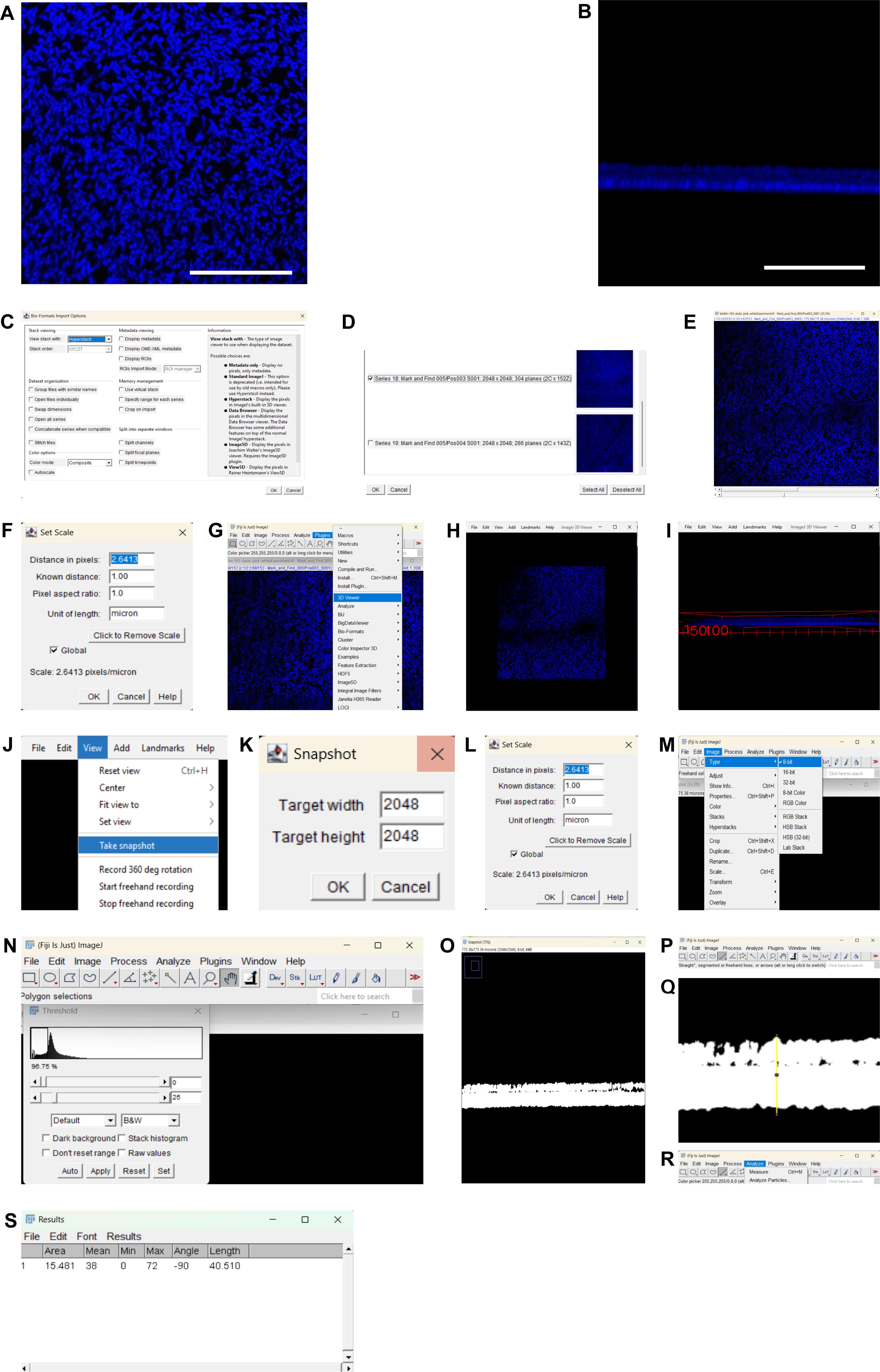
Figure 1. Analysis of biofilms using confocal laser scanning microscopy. A) Single cross-section of the biofilms. All such cross-sections were captured along the Z-axis, resulting in a 3-dimensional reconstruction. B) From 1A, the thickness of the biofilm was measured. C) First, the image was opened in FIJI, and from the Bio-Formats Import options, “hyperstack” and “composite” were chosen. D) The desired field to be analyzed was selected again. E) The image was opened as shown. The default scale was applied by the LasAF imaging software during the acquisition. From the FIJI main menu, the set scale option from the Analyze tab was selected. F) The set scale tab appeared, and scale was noted down. G) From the Plugins tab, the 3D-Viewer was selected. H) The image was opened in the ImageJ 3D viewer module. I) It was set in the side view position. J) From the view tab in the ImageJ 3D viewer module, a snapshot of the image was taken. K) A snapshot was saved using the default image resolution. L) Then, the previous scale values from the set scale option under the Analyze tab were used. M) The image was converted into an 8-bit image. N) The threshold was set to subtract the background from the signal. O) The image was then ready for measurement. P) The line tool from FIJI tools was used to measure thickness. Q–R) The thickness of the biofilm was measured by pressing Ctrl + M. S) This shows the measured value of the biofilm thickness.
2. Image acquisition in Apreo Volume Scope FEI
a. Set the voltage to 10 kV and image at different magnifications (250×, 1,250×, 2,500×, and 5,000×).
b. An image captured at 2,500× is shown in Figure 2A.
D. Analysis of images
1. Drag and drop the captured images onto FIJI.
2. Select the color mode to composite and view stack with hyperstack (Figure 1C–E) in the Bio-Formats Import options.
3. Export a representative image of the top view in JPEG or TIFF format by navigating to File > Save As > TIFF or JPEG.
4. Reopen the TIFF or JPEG image in FIJI by dragging and dropping it onto the software.
5. Adjust the brightness and contrast by going to Image > Adjust > Brightness/Contrast and modifying the bars, then click Apply.
6. For the original imported image, set the scale either by using the imaging software’s preset or by going to Analyze > Set Scale and specifying the parameters (Figure 1F).
7. Draw the scale bar to the desired length using the Straight tool in the FIJI toolbox.
8. Create the scale bar by navigating to Analyze > Tools > Scale Bar.
9. Open the 3D viewer by going to Plugins > 3D Viewer (Figure 1G).
10. In the pop-up add window, select only the blue channel.
11. Set the resampling factor to 2 and click OK. Wait for buffering to complete.
12. Now, adjust the position using the mouse to ensure the thickness is visible and zoom in until the two side red borders meet the edge (Figure 1B and I).
13. From the ImageJ 3D Viewer view option, select Take snapshot and choose the original image’s resolution (e.g. 2,048 × 2,048) (Figure 1J–K).
14. Set the scale again by navigating to Analyze > Set Scale and manually entering the same parameters as in the original image (Figure 1L).
15. Convert the image to an 8-bit image by going to Image > Type > 8-bit (Figure 1M).
16. Set the threshold by going to Image > Adjust > Threshold, keeping parameters at Default and B&W (Figure 1N).
17. Adjust the second slide bar to make the signal prominent from the background and close the dialogue.
18. Select the Straight tool from the toolset and draw a straight line perpendicular to the planes to cover the thickness (Figure 1P–R).
19. Press Ctrl + M to measure the biofilm thickness. Take at least 25 measurements across the biofilm from each image.
20. A results tab will appear containing all the measurements. Use only the length of information and record it in a table format, ensuring the angle is ~90° (Figure 1S).
21. Plot the data in GraphPad Prism to create graphs and test the significance between replicates and test conditions.
E. Pseudocoloring: for better visualization and differentiation
1. Perform pseudocoloring in Adobe Photoshop CC 2019 using overlay mode (Figure 2A and B).
2. Select different objects seen using the quick selection tool and create a new layer.
3. Use the Paint Bucket tool to fill in color in the selection in the new layer.
4. Set the blending mode of the new layer to multiply.
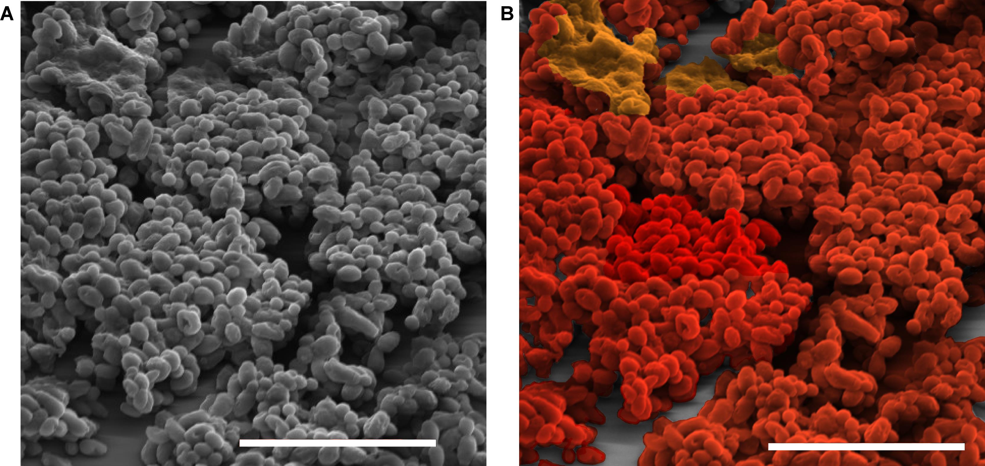
Figure 2. SEM imaging and pseudocoloring. A). Ultrastructure of a biofilm. B). Photoshop overlay to color the different ultrastructures of the biofilm. Scale bar is 20 μm.
Validation of protocol
This protocol has been previously used and validated in the following research article:
Biswas et al. [16]. A Novel Robust Method Mimicking Human Substratum to dissect the Heterogeneity of Candida auris Biofilm Formation. Microbiology Spectrum (Figures 2–4, 6).
General notes and troubleshooting
1. To prevent coverslips from sticking and being damaged while trying to remove them from surfaces, use the lid of a Petri dish and place the coverslips at an angle to prevent them from sticking to the surface completely.
2. It is crucial to use ice-cold water to prevent the formation of gelatin clumps. Clumping can interfere with the coating process and lead to inconsistent results. Therefore, always ensure the water used is sufficiently cold to maintain the gelatin in a smooth, even solution.
3. Carefully following the water washing steps is equally important. Any residual chemicals from previous steps can carry forward to subsequent reactions, potentially preventing proper gelatin coating onto the surfaces. To avoid this, adhere strictly to the washing protocols provided, ensuring thorough and complete rinsing between each step.
4. If you notice that the biofilm remains in a monolayer or has very few cells adhering to the coverslips, this might indicate insufficient washing. In such cases, the number of washing steps with water should be increased. This additional washing can help remove any inhibiting substances and allow for a more robust biofilm formation.
5. It is essential to dry the water completely before proceeding to the next step. Residual moisture can interfere with the reactions, leading to incomplete or failed biofilm formation. Make sure to allow adequate drying time or use appropriate methods to ensure that all water is evaporated before moving forward.
6. Handling the biofilms gently is also critical, especially when pipetting to exchange media or during other manipulations. Biofilms can be fragile, and rough handling can disrupt their structure, leading to inaccurate experimental results. Use gentle pipetting techniques and avoid vigorous movements to maintain the integrity of the biofilms.
7. When using FIJI software for image analysis, avoid maximizing the window. Maximizing the FIJI window can cause the picture to load improperly, which may interfere with image processing and analysis. Keep the window in its default size to ensure smooth operation and prevent software issues.
8. In addition to these specific steps, general troubleshooting tips include ensuring that all equipment and materials are prepared and used correctly. If the coverslips are not fully coated and the biofilm is not forming as expected, revisit each step of the protocol to identify any potential deviations or mistakes. Proper coating and biofilm formation are critical for obtaining reliable results.
9. For imaging issues with both microscopy and SEM, ensure that the biofilm preparation is consistent and the equipment is correctly calibrated. If problems persist, consult the equipment manuals or seek advice from colleagues or technical support.
10. By adhering to these detailed steps and precautions, the quality and reliability of biofilm experiments can be significantly improved. Be meticulous in following protocols and addressing any issues promptly to achieve the best possible outcomes.
Acknowledgments
This work was supported by the Ramalingaswami fellowship grant from the Department of Biotechnology, India and the Science and Engineering Research Board (SERB) DST project funding (EEQ/2022/000606). The protocol described in this paper was published in Microbiology Spectrum (Biswas et al. [16]). A Novel Robust Method Mimicking Human Substratum To Dissect the Heterogeneity of Candida auris Biofilm Formation. 10.1128/spectrum.00892-23.
Competing interests
The authors declare no conflicts of interest.
References
- Brouwer, A. E., van Kan, H. J. M., Johnson, E., Rajanuwong, A., Teparrukkul, P., Wuthiekanun, V., Chierakul, W., Day, N. and Harrison, T. S. (2007). Oral versus Intravenous Flucytosine in Patients with Human Immunodeficiency Virus-Associated Cryptococcal Meningitis. Antimicrob Agents Chemother. 51(3): 1038–1042.
- Allaw, F., Kara Zahreddine, N., Ibrahim, A., Tannous, J., Taleb, H., Bizri, A. R., Dbaibo, G. and Kanj, S. S. (2021). First Candida auris Outbreak during a COVID-19 Pandemic in a Tertiary-Care Center in Lebanon. Pathogens. 10(2): 157.
- Satoh, K., Makimura, K., Hasumi, Y., Nishiyama, Y., Uchida, K. and Yamaguchi, H. (2009). Candida auris sp. nov., a novel ascomycetous yeast isolated from the external ear canal of an inpatient in a Japanese hospital. Microbiol Immunol. 53(1): 41–44.
- Garcia-Effron, G., (2020). Rezafungin—Mechanisms of Action, Susceptibility and Resistance: Similarities and Differences with the Other Echinocandins. J Fungi. 6(4): 262.
- Abe, M., Katano, H., Nagi, M., Higashi, Y., Sato, Y., Kikuchi, K., Hasegawa, H. and Miyazaki, Y. (2020). Potency of gastrointestinal colonization and virulence of Candida auris in a murine endogenous candidiasis. PLoS One. 15(12): e0243223.
- Lee, W. G., Shin, J. H., Uh, Y., Kang, M. G., Kim, S. H., Park, K. H. and Jang, H. C. (2011). First Three Reported Cases of Nosocomial Fungemia Caused by Candida auris. J Clin Microbiol. 49(9): 3139–3142.
- Morales-López, S. E., Parra-Giraldo, C. M., Ceballos-Garzón, A., Martínez, H. P., Rodríguez, G. J., Álvarez-Moreno, C. A. and Rodríguez, J. Y. (2017). Invasive Infections with Multidrug-Resistant Yeast Candida auris, Colombia. Emerg Infect Dis. 23(1): 162–164.
- Organization, W. H., (2022). WHO fungal priority pathogens list to guide research, development and public health action. World Health Organization.
- Cristina, M. L., Spagnolo, A. M., Sartini, M., Carbone, A., Oliva, M., Schinca, E., Boni, S. and Pontali, E. (2023). An Overview on Candida auris in Healthcare Settings. J Fungi. 9(9): 913.
- Omardien, S. and Teska, P. (2024). Skin and hard surface disinfection against Candida auris– What we know today. Front Med. 11e1312929.
- Cadnum, J. L., Shaikh, A. A., Piedrahita, C. T., Sankar, T., Jencson, A. L., Larkin, E. L., Ghannoum, M. A. and Donskey, C. J. (2017). Effectiveness of Disinfectants Against Candida auris and Other Candida Species. Infect Control Hosp Epidemiol. 38(10): 1240–1243.
- De Gaetano, S., Midiri, A., Mancuso, G., Avola, M. G. and Biondo, C. (2024). Candida auris Outbreaks: Current Status and Future Perspectives. Microorganisms. 12(5): 927.
- Horton, M. V., Johnson, C. J., Kernien, J. F., Patel, T. D., Lam, B. C., Cheong, J. Z. A., Meudt, J. J., Shanmuganayagam, D., Kalan, L. R. and Nett, J. E. (2020). Candida auris Forms High-Burden Biofilms in Skin Niche Conditions and on Porcine Skin. mSphere. 5(1): e00910–19.
- Sherry, L., Ramage, G., Kean, R., Borman, A., Johnson, E. M., Richardson, M. D. and Rautemaa-Richardson, R. (2017). Biofilm-Forming Capability of Highly Virulent, Multidrug-Resistant Candida auris. Emerg Infect Dis. 23(2): 328–331.
- Biswas, B., Gangwar, G., Nain, V., Gupta, I., Thakur, A. and Puria, R. (2022). Rapamycin and Torin2 inhibit Candida auris TOR: Insights through growth profiling, docking, and MD simulations. J Biomol Struct Dyn. 41(17): 8445–8461.
- Biswas, B., Rana, A., Gupta, N., Gupta, I., Puria, R. and Thakur, A. (2023). A Novel Robust Method Mimicking Human Substratum To Dissect the Heterogeneity of Candida auris Biofilm Formation. Microbiol Spectrum. 11(4): e00892–23.
Article Information
Publication history
Received: Jul 5, 2024
Accepted: Oct 23, 2024
Available online: Nov 20, 2024
Published: Jan 5, 2025
Copyright
© 2025 The Author(s); This is an open access article under the CC BY-NC license (https://creativecommons.org/licenses/by-nc/4.0/).
How to cite
Biswas, B., Asif, S., Puria, R. and Thakur, A. (2025). A Novel and Robust Method for Investigating Fungal Biofilm. Bio-protocol 15(1): e5146. DOI: 10.21769/BioProtoc.5146.
Category
Microbiology > Microbial biofilm > Biofilm culture
Biological Sciences > Microbiology
Do you have any questions about this protocol?
Post your question to gather feedback from the community. We will also invite the authors of this article to respond.