- Protocols

- Articles and Issues
- For Authors
- About
- Become a Reviewer

A High-Throughput Droplet-based Method to Facilitate Microbial Conjugation
(*contributed equally to this work, § Technical contact) Published: Vol 14, Iss 23, Dec 5, 2024 DOI: 10.21769/BioProtoc.5120 Views: 1830
Reviewed by: Alba BlesaMercedes SanchezFernando A Gonzales-Zubiate
Original research article
The authors used this protocol in:
Jul 2024
Advertisement


Protocol Collections
Comprehensive collections of detailed, peer-reviewed protocols focusing on specific topics


Related protocols
Abstract
Droplet microfluidic platforms have been broadly used to facilitate DNA transfer in mammalian and bacterial hosts via methods such as transformation, transfection, and conjugation, as introduced in our previous work. Herein, we recapitulate our method for conjugal DNA transfer between Bacillus subtilis strains in a droplet for increased conjugation efficiency and throughput of an otherwise laborious protocol. By co-incubating the donor and recipient strains in droplets, our method confines cells into close proximity allowing for increased cell-to-cell interactions. This methodology is advantageous in its potential to automate and accelerate the genetic modification of undomesticated organisms that may be difficult to cultivate. This device is also designed for modularity and can be integrated into a variety of experimental workflows in which fine-tuning of donor-to-recipient cell ratios, growth rates, and media substrate concentrations may be necessary.
Key features
• Builds on previous Bacillus-conjugation methods introduced by Brophy et al. [1] increasing the throughput by flowing the donors and recipients into a droplet microfluidic chip.
• Experiments performed on this chip increase conjugation efficiency as compared to conjugation performed traditionally by co-incubating the cells in free culture.
• This platform enables fine-tuning of experimental parameters, e.g., donor-to-recipient cell ratios, induction concentration, and incubation times, all critical factors in engineering undomesticated organisms.
• Adaptable for upstream automation of bacterial cultivation and downstream analysis of transconjugants encapsulated in droplets.
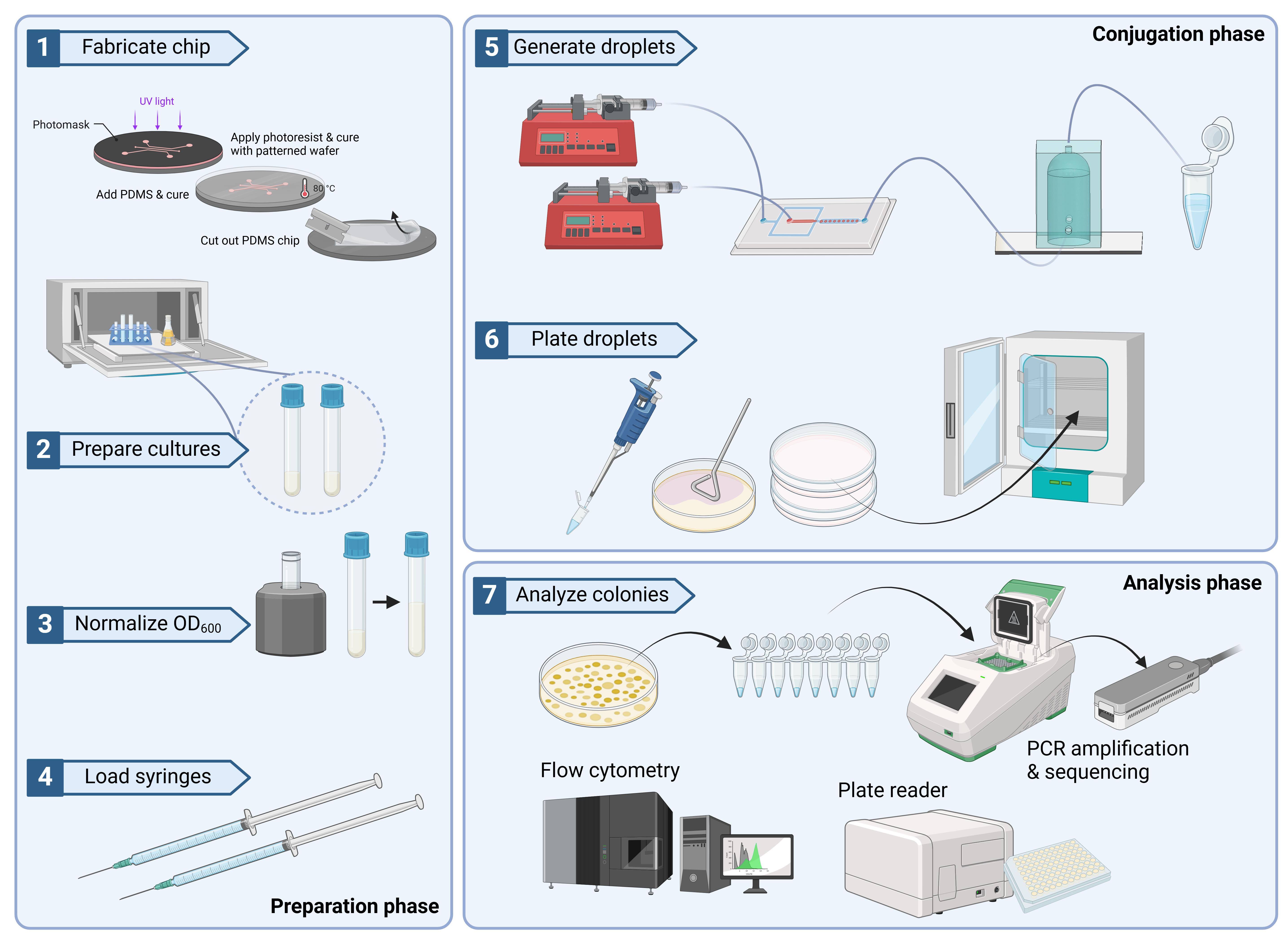
Keywords: Droplet microfluidicsGraphical overview
Background
Droplet microfluidic platforms have been broadly used to enable facile transformation of both mammalian and microbial cells in a high-throughput manner. This has been demonstrated through microfluidic electroporation of droplet-encapsulated cells [2,3], chemically-mediated transformation of cells (in some instances with heat shock added) [4,5], as well as transfection through means of mechanoporation [6], which has even been demonstrated in difficult-to-transfect primary T lymphocytes [7], moving toward CAR-T applications.
As evidenced, there exists a wide array of droplet-based microfluidic tools and techniques developed to streamline transformation and transfection, yet conjugative methods of DNA transfer have been scarcely explored. While conjugation is a modality of DNA transfer exclusive to microbial species, it is a powerful method commonly used to introduce heterologous DNA into microbial hosts that may be less amenable to modification. A canonical example of this is E. coli-based conjugation between F+ and F- cells. In this case, E. coli containing an F plasmid are able to synthesize a pilus structure allowing for DNA to be transferred during cell-to-cell contact [8]. Conversely, Agrobacterium-mediated DNA transfer, which leverages its native pathogenic functions to transfer DNA to a microbial or plant host, is able to do so through a Type IV secretion system [9]. Lastly, a unique example of conjugation is that of some strains of B. subtilis, which involves the transfer of integrative conjugative elements (ICE) from one host to the other. The XPORT strain [1], used in this protocol, is an engineered donor strain with a modified ICE. In the aforementioned work, this strain was used to transfer DNA via conjugation to a broad array of undomesticated strains of Bacillus and other related strains. Moreover, XPORT has demonstrated survivability and successful conjugation in soil environments where cell growth is uncontrolled. While the biological components of the system are robust, we have designed a microfluidic platform (previously introduced in Wippold et al. [10]) that offers more experimental control and complements the workflow described by Brophy et al. [1], expediting an otherwise laborious protocol and enabling easy optimization of experimental parameters such as donor-to-recipient ratios.
Although there have been other efforts demonstrating in-droplet conjugation, such as that introduced by Lam et al. [11], we propose two advantages to our protocol: (1) The lower surfactant concentration, which yields higher cell viability and enables longer incubation times if needed, and (2) the additional micro-vessel (on the secondary chip), which allows for accurate timing over co-incubation times with the first-in, first-out system. We also acknowledge several disadvantages to this device: (1) The current system does not allow for in-line sorting of successful transconjugants from unconjugated recipients, (2) there is no option for facile, on-chip incubation besides placing the entire device in an incubated chamber, and (3) the current tandem (two-chip) system introduces more potential points of failure, such as leakage between the fluidic tubing connections and the increased potential for air bubble introduction at the tubing-chip interfaces. For example, a downstream reagent inlet stream can be incorporated into the microfluidic platform that allows for the injection of a microdroplet breaking reagent (such as the commercial PicoBreak solution or 1H,1H,2H,2H-perfluoro-1-octanol PFO) to controllably release the inner contents of the droplets. Another possibility is to pair a commercial droplet sorting and plating system (such as the one marketed by On-Chip Biotechnologies or Atrandi Biosciences) to enable a mechanism to detect, sort, and place desired droplets into known areas.
Overall, we envision several areas of application for this device beyond the scope of what is presented in this work, which solely leverages B. subtilis to B. subtilis conjugation. This device can potentially be used with other donor organisms designed for conjugation (e.g., Agrobacterium tumefaciens AGL1) or perhaps even expanded to a tri-parental mating system, such as that described in Banta et al. [12] and Heinze et al. [13]. Moreover, with the addition of upstream and downstream modules, one may also automate the culturing steps leading up to the conjugation as well as the breakage of droplets and subsequent plating steps.
Materials and reagents
Biological materials
Donor strain JAB981 (from Brophy et al. [1]), B. subtilis JH642 Δ(ydcS-yddM)::[(Pspank-GFPmut2) tet(M) cat] thrC::[(int-yddJ) ΔnicK mls] alrA::[(Psweet-rapI) spc]
Recipient strain JAB545 (from Brophy et al. [1]), B. subtilis PY79 cured of ICEBs1, ΔcomC:: aphA-3
Reagents for bacterial culture
LB Miller (Fisher Scientific, catalog number: BP1426-2)
Agar (Fisher Scientific, catalog number: BP1423-500)
Phosphate buffered saline (PBS) (VWR, catalog number: 97062-336)
D-alanine (Sigma-Aldrich, catalog number: A7377)
Tetracycline hydrochloride (Calbiochem, catalog number: 583411; may alternatively use Sigma-Aldrich, catalog number: T7660)
Isopropyl β-d-1-thiogalactopyranoside (IPTG) (Sigma-Aldrich, catalog number: I5502)
NH4Cl (Sigma-Aldrich, catalog number: A9434)
MgCl2 (Sigma-Aldrich, catalog number: M8266)
K2HPO4·3H2O (Sigma-Aldrich, catalog number: P5504)
Materials for chip fabrication and use
SU-8 2075 photoresist (Kayaku, formerly Microchem Corp)
SU-8 2050 photoresist (Kayaku, formerly Microchem Corp)
Microposit EBR 10A (Kayaku, formerly Microchem Corp)
IP-S (Nanoscribe GmbH)
Tridecafluoro-1,1,2,2 tetrahydrooctyl trichlorosilane (United Chemical Technologies LLC, catalog number: T2492)
Poly(dimethylsiloxane) (PDMS) (Dow Corning Corp, PDMS Sylgard 184, catalog number: 761028-5EA)
3-(trimethoxysilyl)propyl methacrylate (Sigma-Aldrich, catalog number: 440159)
Propylene glycol monomethyl ether acetate (PGMEA) (Sigma-Aldrich, catalog number: 484431)
99% isopropyl alcohol (ULINE, catalog number: S20735)
EBR-10 A (Microposit Kayaku Advanced Materials)
3M Novec 7500 Engineered Fluid (3M, catalog number: 7100025016)
PicoSurf (Sphere Fluidics, catalog number: C021)
Reagents for confirmation assays
Q5 polymerase (NEB, catalog number: M0491L)
dNTPs (NEB, catalog number: N04475)
Q5 reaction buffer (NEB, catalog number: B9027S)
10 μM primers (IDT, exact sequences are noted in the protocol)
Sheath fluid for flow cytometry (Thermo Scientific, NERL Blood Bank Saline, catalog number: 8504)
ReadyLyze Lysozyme (LGC Biosearch Technologies, Lucigen, catalog number: R1804M)
MasterPure Total Nucleic Acid Isolation Kit (LGC Biosearch Technologies, Lucigen, catalog number: MC85200)
Solutions
Tris-Spizizen salts (TSS) buffer (see Recipes)
Carrier (oil) phase for ENTRAP device (see Recipes)
LB agar (see Recipes)
Recipes
Tris-Spizizen salts (TSS) buffer
Reagent Final concentration Quantity or Volume NH4Cl 150 mM 2 g K2HPO4·3H2O 20 mM 0.35 g Tris base (pH 7.5) 49.5 mM 6 g MgCl2 125 mM 11.9 g H2O n/a 1,000 mL Carrier (oil) phase for ENTRAP device
Reagent Final concentration Quantity or Volume PicoSurf (5% in Novec 7500) 1.25% (v/v) 1 mL Novec 7500 n/a 4 mL Total n/a 5 mL LB agar (250 mL)
Reagent Final concentration Quantity or Volume LB 2.5% (w/v) 6.25 g Agar 1.5% (w/v) 3.75 g H2O n/a 250 mL
Laboratory supplies
15 mL culture tubes (Corning, Falcon, catalog number: 352059)
5 mL plastic syringe (BD, catalog number: 309646)
1 mL plastic syringe (BD, catalog number: 309628)
0.2 μm Whatman Puradisc 13 syringe filter (Sigma-Aldrich, catalog number: WHA67801302)
Microtube-130 AFA fiber for sonication (Covaris, catalog number: 520216)
Short Read Eliminator XS kit (Circulomics (PacBio))
Non-DEHP tubing, 30 gauge (Saint-Gobain Performance Plastics, Tygon ND-100-80, catalog number: VWR 89404-300)
Micropipettes 100–1,000 μL (VWR, Eppendorf, catalog number: 89125-306)
Pipette tips 1,000 μL (USA Scientific, TipOne, catalog number: 1122-1830)
96-well microplate (Corning, catalog number: 353072)
Glass slides, 75 × 50 (Corning, catalog number: 2947)
Equipment
Microcentrifuge (Eppendorf, model: Centrifuge 5420)
Shaking incubator (New Brunswick, Innova 42R, catalog number: M1335-0080)
Spectrophotometer (VWR, model: Biowave CO8000 Cell Density Meter)
Stationary incubator (Thermo Fisher Scientific, Heratherm, catalog number: 50125590)
Focused ultrasonicator for genome extractions (Covaris E220 Evolution, catalog number: 500429)
Desiccator (Zoro, catalog number: G4655463)
Spin coater (Laurell Technologies Corporation, model: H6-23)
Photolithography mask aligner (EVG Group, model: EVG 610)
Syringe pump (Chemyx, Fusion 200-X, catalog number: 0720X)
Plasma cleaner (Harrick Plasma, catalog number: PDC-32G)
Optical microscope (Zeiss, model: Colibri Axiovert 200)
Nanoscribe Photonics Professional GT (Nanoscribe GmbH)
Software and datasets
Geneious 2023 (paid software for genetic mapping)
Alternative genetic mapping software: Benchling (free online interface for gene editing)
AutoCAD (paid software for designing master molds)
Alternative CAD software for silicon mold design: Blender, FreeCAD
Filtlong v0.2.1 (https://github.com/rrwick/Filtlong.git)
Raven v1.7.0 (https://github.com/lbcb-sci/raven.git)
medaka v1.4.2 (https://github.com/nanoporetech/medaka.git)
prokka v1.14.5 (https://github.com/tseemann/prokka.git)
Procedure
Device fabrication
Option 1: Traditional photolithography method to fabricate master mold on silicon wafer
Spin coat SU-8 2050 onto a silicon wafer at 2,100 rpm. See General note 1.
Apply the first soft baking step at 65 °C for 24 h.
Apply the second soft baking step at 95 °C for 20 min.
Expose the coated Si wafer in the photolithography mask aligner using a mask design (either screen printed or using chromium mask processing) wafer using standard i-line (365 nm) and a total dose of 1,000 mJ/cm2 (Figure 1).
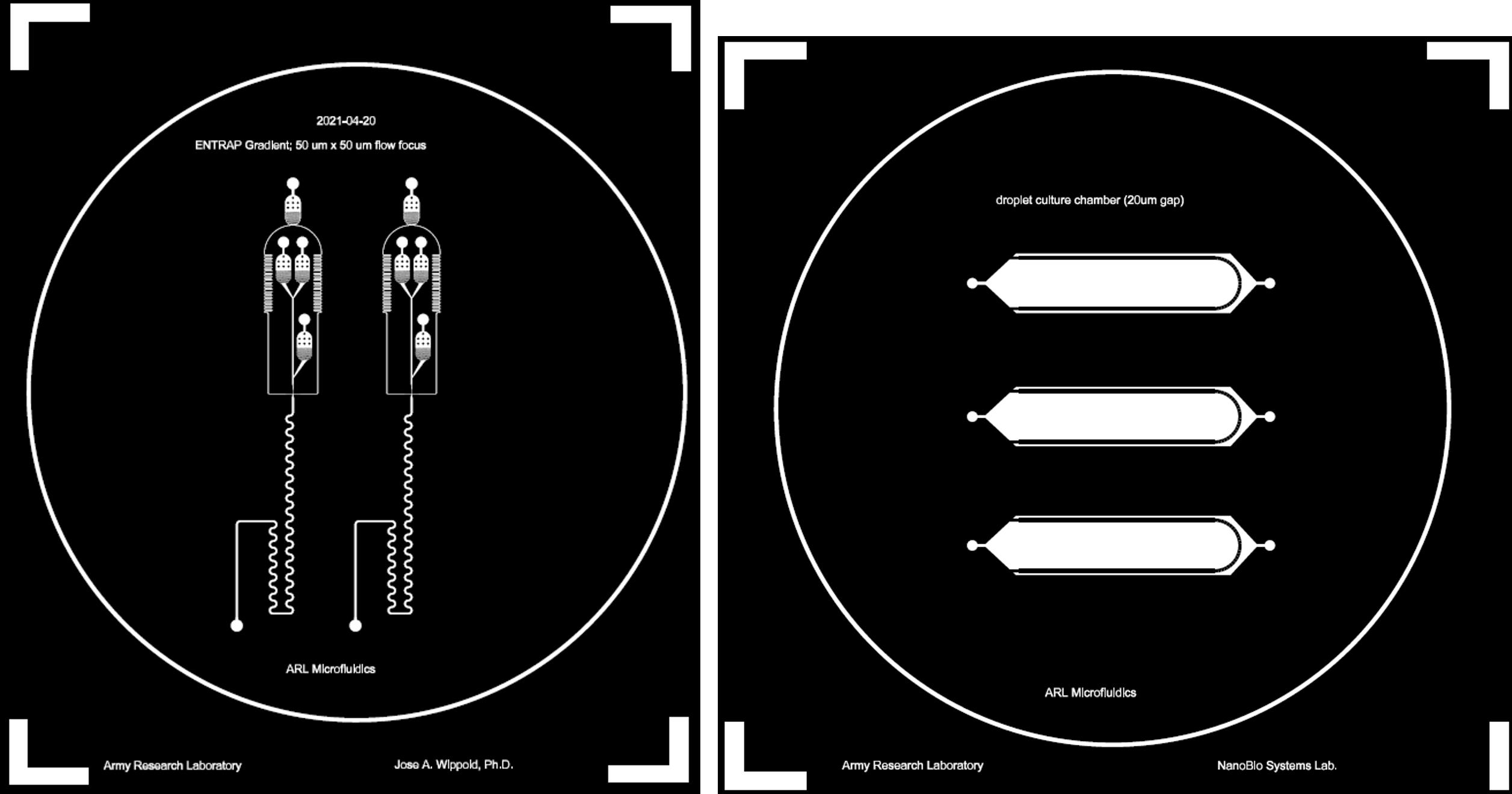
Figure 1. Mask designs used for the photolithography-based master mold process during the microfluidic device fabrication workflow. Left: DNA ENTRAP mask designs. Right: Microdroplet observation chamber device.Apply a post-exposure baking step at 65 °C for 40 min, then 95 °C for 20 min.
Remove the unexposed photoresist using EBR-10A (commercial Edge Bead Remover solution engineered to eliminate any unexposed negative photoresist).
Using a conventional desiccator, apply a coating of tridecafluoro-1,1,2,2 tetrahydrooctyl trichlorosilane for 60 min. See General note 2.
For this, orient all wafers to be silanized feature-side up. Apply 2–4 drops of trichlorosilane (using a plastic pipettor; roughly 100 μL total) to a small weigh boat.
Option 2: Two-photon lithography method to fabricate master mold on silicon wafer.
For the devices used in this work, two approaches can be used for the fabrication of the microfluidic master molds that are used to conduct the soft lithography steps (i.e., the replica molding step to create the PDMS chips). We used a typical SU-8 photolithography approach along with a two-photon polymerization approach, depending on the overall geometry and footprint of the microfluidic chips that were designed. See General note 3.
Silanizing the silicon wafer
i. Make a bath of 1% solution of coupling agent [3-(trimethoxysilyl)propyl methacrylate] in ethanol.
ii. Submerge substrates overnight. Submerging can be expedited using only a 4 h period, if timing is an issue.
iii. Remove the substrate from the chemical bath, rinse with distilled water, and dry using a N2 gun.
iv. Store wafers in an airtight container at room temperature for up to 3 months. See General note 4.
Adding IP-S photoresist
i. Apply a volume of IP-S resist sufficient to cover the intended footprint of the microfluidic geometry to be fabricated.
ii. Gently spin the photoresist (500 pm) for 60 s to ensure an even spreading.
Running Nanoscribe
i. Run fabrication using Nanoscribe 2PP tool.
Upload the .STL file to the two-photon polymerization software tool: DeScribe.
Fabricate the master mold pattern on the Nanoscribe Photonics Professional GT (Nanoscribe GmbH, Germany) using the pretreated silicon wafer as the substrate and negative photoresist (IP-S, Nanoscribe GmbH, Germany) using a power scaling of 1.0, tetrahedron inner scaffold, base scan speeds of 50,000, base laser power of 60%, shell/scaffold scan speeds of 100,000, and shell/scaffold laser power intensities set at 70%. For more details regarding this method, see Wippold et al. [14].
Developing
i. Following the fabrication run, remove the wafers from the tool and develop in propylene glycol monomethyl ether acetate (PGMEA) for 6 min.
ii. For fine development, place the wafers containing the master mold in 99% isopropyl alcohol (IPA) for 10 min.
iii. Following the IPA bath, dry the masters gently with nitrogen gas and inspect under a microscope for quality assurance [14].
Post-fabrication silanization of microfabricated structures
Following the inspection, coat the patterned wafers with tridecafluoro-1,1,2,2 tetrahydrooctyl trichlorosilane for 20 min to prevent pattern removal during PDMS replication [14].
Generating the ENTRAP device using PDMS
Mix ~22 g of PDMS (2 g of curing agent and 20 g of polymer material; 1:10 ratio as specified by the manufacturer). See Figure 2.
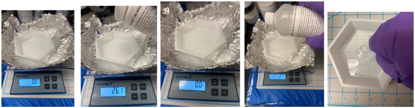
Figure 2. Stepwise procedure from weighing PDMS pre-polymer to mixing the pre-polymer with the curing agentPlace the silicon wafer mold (fabricated in steps A1–2) into a Petri dish or any clean container large enough to fit the silicon wafer. Pour 20 g of material over the mold (Figure 3). See General note 5.
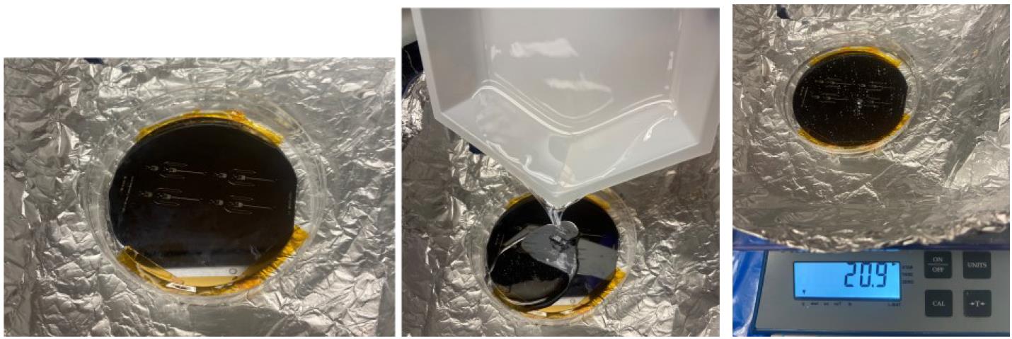
Figure 3. Stepwise procedure for pouring mixed PDMS onto a silicon master mold attached via Kapton tape to a plastic Petri dishFor ease of removal of the PDMS post-curing, secure the Si-SU-8 master mold to the Petri dish using Kapton tape along the edges of the mold. Place the Petri dish containing the PDMS-covered wafer into a desiccator and apply vacuum pressure to remove bubbles. Bubbles may also be popped with a pipette tip (Figure 4).
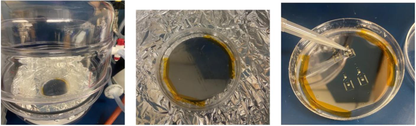
Figure 4. Stepwise procedure for de-gassing the mixed PDMS and removing all bubblesAllow PDMS to cure over the mold either at room temperature (~25 °C) overnight on a level surface or at 65 °C for ~1–4 h in an oven (Figure 5).
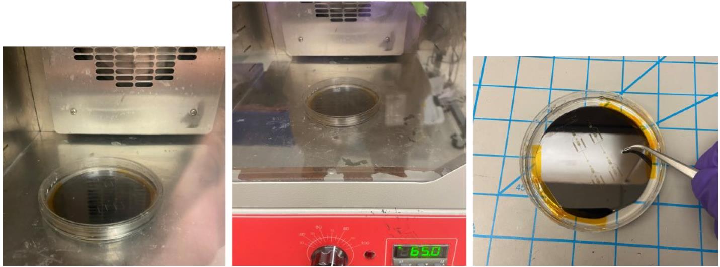
Figure 5. Stepwise procedure for oven-curing a PDMS mold
Fabricating the bottom surface of the channels
Using the PDMS made in step A3, coat a clean glass slide with a thin layer of PDMS (30 μm thickness) by spin-coating at 3,000 rpm for 30 s.
Allow this PDMS to cure under the same conditions as in step A3c. See General note 6.
Bonding the ENTRAP device to the PDMS-coated glass slide and preparing for experimentation
Carefully, using a scalpel or razor, cut a large rectangle in the PDMS around the channel patterns (Figure 6).
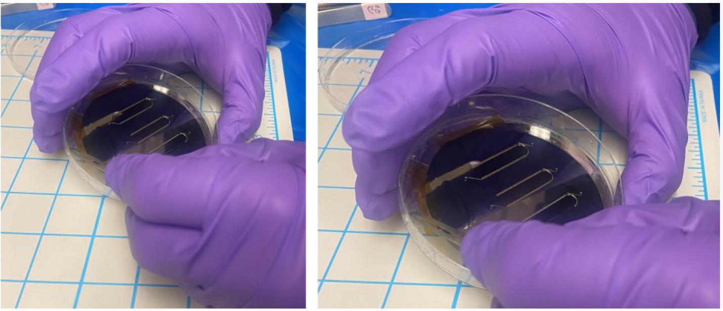
Figure 6. Stepwise procedure for removing a PDMS microfluidic molded device from the silicon master mold waferRemove the PDMS rectangle (which contains the channels) from the silicon wafer and place it on the PDMS-coated glass slide. See General note 7.
Introduce tubing for the inlet and outlets of the device
Use a needle to poke holes in the device where the inlets and outlets are designed (Figure 7).
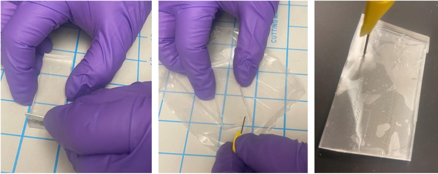
Figure 7. Stepwise procedure for preparing a PDMS microfluidic molded device for oxygen plasma bonding (final step)
Oxygen plasma bonding
Place the device in the plasma cleaner and apply a 90 s plasma treatment at a power of 150 W and a pressure of 150 mTorr (Figure 8).
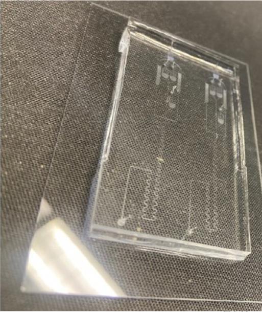
Figure 8. Bonded microfluidic chip (two identical experimental patterns) following successful oxygen plasma bondingPlace Tygon tubing in the holes for each of the inlets (one for the oil inlet, one for the cells) and one for the outlet.
Connect the outlet tube to the second chip containing the micro-vessel system for incubation of the cells.
Cell culture preparation
Streak strains from glycerol stock onto LB agar plates with selection antibiotics. B. subtilis donor strain JAB981 should be struck onto LB agar supplemented with tetracycline (10 μg/mL) and D-alanine (100 μg/mL). B. subtilis recipient strain JAB545 should be struck onto LB agar; supplementation with chloramphenicol (10 μg/mL) is optional.
Incubate these streaked agar plates overnight (>14 h) at 37 °C. Pause point.
Ensure that at least 25 mL of LB is available for the entirety of the culturing and dilution process described ahead. Pick a single large colony from the plates and suspend this colony in 3 mL of LB liquid media supplemented with the same selection antibiotics that were on the agar media. See General note 8.
Culture the donor and recipient strain to an OD600 between 0.8 and 1.2, as read on the spectrophotometer.
At this point, subculture these strains into fresh media with the same selection antibiotics (culture volumes: 3–5 mL).
Allow the donor strain to grow to an OD600 of 0.2; at this point, xylose should be added to the culture to a final concentration of 1%.
Critical: This step serves to induce the conjugation machinery in the donor strain. No conjugation will occur without this.
Culture both strains to an OD600 between 0.8 and 1.0. See General note 9.
Pellet cultures by centrifugation at 3,000× g for 3 min.
Wash pellets with 1 mL of PBS and re-centrifuge at 3,000× g for 3 min. Repeat twice.
Resuspend both pellets in either TSS media (Recipe 1) or LB media supplemented with D-alanine (100 μg/mL) to a final OD600 of 0.6. See General note 10.
Conjugation of cells in the ENTRAP device
Prior to experimentation, the fully fabricated PDMS DNA ENTRAP microdevices should be baked at 80 °C for 4 h to ensure a state of ensured hydrophobicity.
Combine the donor cells with recipient cells at a 1:1 ratio. This step is optional, should you wish to keep the donor and recipient cells separate and use separate inlets for each. In such a case, use the chip designed with two reagent inlets. See General note 11.
Load at least 500 μL of the donor/recipient cell mix into a 1 mL BD plastic syringe.
Prepare the oil phase solution according to Recipe 2. Filter the solution through a 0.2 μm filter before use.
Prime all microfluidic channels and devices with the oil phase solution prior to operation.
Load 5 mL of the carrier oil/surfactant mixture (Novec 7500/PicoSurf) into a 5 mL BD plastic syringe.
Place the loaded syringes into separate Chemyx Fusion 200 pumps. For the syringe containing the cell suspension, set the syringe pump at a flow rate of 400 μL/h. For the syringe containing the carrier phase (oil + surfactant), set the syringe pump to a flow rate of 2,000 μL/h. See General note 12. Also, see Figure 9 for a deconstructed view of the tubing arrangement.
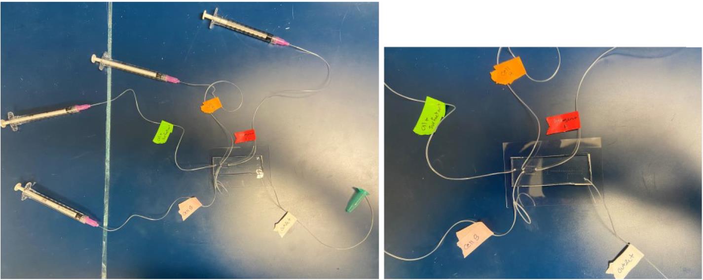
Figure 9. Tubing layout of ENTRAP device. Left image: DNA ENTRAP front-end microfluidic system with labeled reagent syringes. Right image: Close-up of the left image. Green tag: oil and surfactant phase. Orange tag: inlet for cell A. Pink tag: inlet for cell B. Red tag: inlet for inducer reagent. White tag: outlet.Run both syringe pumps to begin droplet formation. Ensure that the outlet tube of the ENTRAP chip is connected to the second chip containing the micro-vessel system (Figure 10), which enables accurately timed incubation periods. Allow the droplets to accumulate in the micro-vessel system.
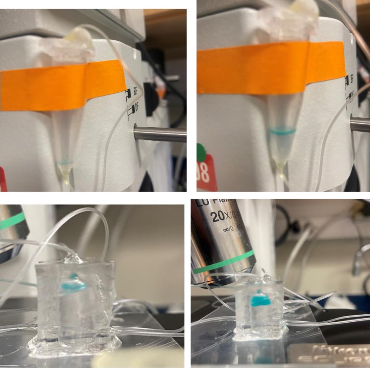
Figure 10. Microfluidic vessel for droplet collection. Top: One example of a microdroplet collection example. Bottom: Example of the microfabricated micro-vessel chamber (droplets filled with blue dye).While droplets are being formed, you may perform imaging under an inverted optical microscope (Figure 11). For the Zeiss AxioObserver Colibri, use the following parameters:
For brightfield imaging, use the 10× objective with a phase contrast (Ph1) ring and 10 ms exposure time at 9 V total light power.
For fluorescent imaging, the corresponding LED (to excite the fluorophore or fluorescent protein) should be used in combination with an appropriate dichroic mirror/beam splitter and emission filter (to remove signal not corresponding to the excited target). For example, with GFP imaging, the BP 469/38 LED should be used to excite the fluorophore, while paired with a triple band pass splitter 405+493+610. LED power should be set to 95% and exposure times ranging from 300 to 3,000 ms. Select the appropriate exposure time that provides satisfactory signal-to-noise feedback. Keep the exposure time consistent across all experimental runs.
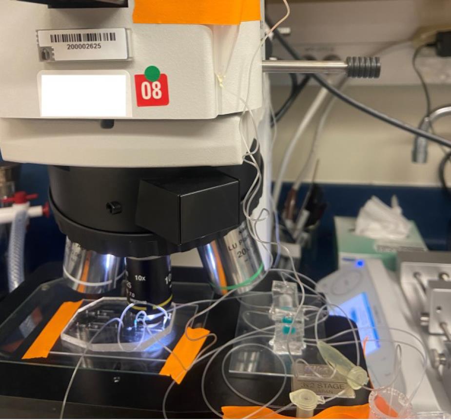
Figure 11. Experimental setup using blue dye–filled droplets for illustrative purposes
You may stop the syringe pumps when you have achieved the desired volume (or expected droplet number). Clip the end of the tube (stopping flow) by placing ~0.5 cm of the outlet tube into a microcentrifuge tube and closing the lid.
Incubate droplets for at least 1 h at ambient temperatures or 37 °C (depending on your recipient strain’s culture constraints). See Figure 12.
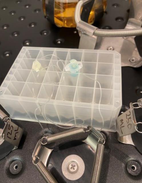
Figure 12. Microdroplet incubation vessel placed in a shake incubatorAfter the desired co-incubation period, flow the droplets out from the micro-vessel chip.
Pipette 50 μL of the droplets that are in oil suspension within the micro-vessel chambers used for conjugation onto a selection agar plate (Figure 13), which may be any media appropriate for transconjugant growth supplemented with 10 μg/mL tetracycline. Spread the droplets (breaking them) using a sterile L-spreader. For the recipient strain, JAB 545, we use LB Miller as the base media. See General note 13.
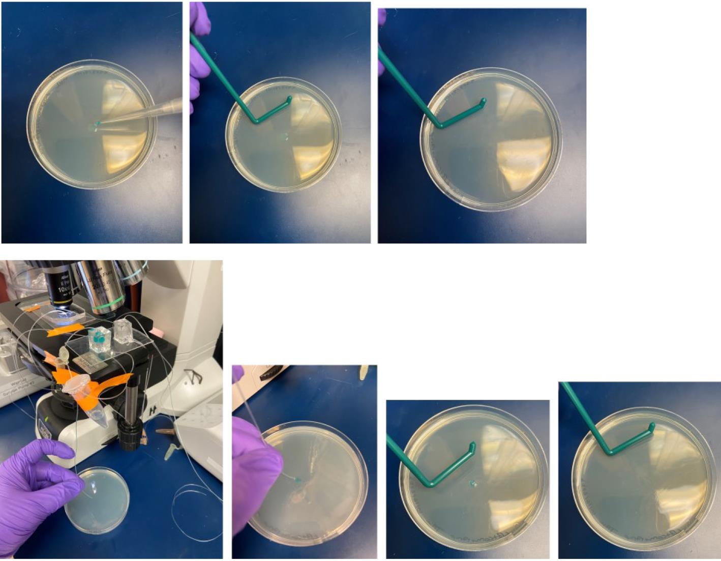
Figure 13. Plating of microdroplets on agar media for transconjugant selection. Top: Plating microdroplets from micro-vessel type 1. Bottom: Plating microdroplets from micro-vessel type 2.For controls and conjugation efficiency calculations, plate the same volume of droplets onto (1) selection agar containing 100 μg/mL D-alanine and 10 μg/mL tetracycline, which will capture both donor and transconjugant, and (2) agar media with no antibiotic or D-alanine supplementation, which will capture untransformed recipients and transconjugants while preventing JAB981 donors from growing due to their auxotrophy.
Incubate the plates (~16 h) in a 37 °C stationary incubator or at the preferred temperature of the recipient strain. Most of the Bacillus recipient strains we have used the XPORT donor with can tolerate 37 °C, but one should take heed to the culture conditions of the recipient when plating for transconjugants. Pause point.
Transconjugant selection and evaluation
After the incubation period, inspect the transconjugant plates (plates with 10 μg/mL tetracycline) for colonies. If colonies have not yet grown, you may need to incubate for longer.
Pick several colonies from the transconjugant plate. Inoculate 3 mL cultures, supplemented with 10 μg/mL tetracycline. After reaching the mid-log phase, sub-culture these strains for improved consistency (across replicates) in expression.
When grown to an OD600 of ~0.2, induce cells with 1 mM IPTG, then shake for 1 h at 37 °C (or whatever temperature suits your recipient strain). Be sure to aliquot a portion of the cultures out as a negative (untreated) control. See General note 14.
After this incubation period, you may choose to perform various analyses to confirm the successful conjugation of DNA into the recipient strain.
Option 1: Flow cytometry. For this type of analysis, prepare a sample by diluting the induced sample and uninduced control in sheath fluid (100-fold dilution). Run the samples using the Sony SA3800 Spectral Analyzer with the following parameters: Threshold FSC value, 0.5%; FSC gain, 17; SSC voltage, 20%; fluorescence PMT voltage, 69.8%; acquisition of 10,000 events.
Option 2: Plate reader for fluorescence measurement. For this type of analysis, prepare the following dilutions of your samples: undiluted, 2-, 4- and 8-fold dilutions. Pipette 200 µL of each sample into a 96-well plate. Read absorbance at 600 nm and fluorescence in accordance with the excitation/emission parameters of the expressed fluorophore. In this work, we measure GFPmut2, which has an excitation/emission of 485 and 508 nm, respectively. Divide the relative fluorescence units (RFUs) by the absorbance at 600 nm of the same sample in order to normalize the difference in cell densities across samples.
Option 3: Fluorescence microscopy. One may use the sample parameters as stated above in step C11 of the above protocol.
Option 4: Colony PCR. Use the following primer sequences, flanking the insertion site, to confirm conjugation success: 5'-AAAGTCTTTTATTCTGCGCCG-3' (forward primer) and 5'-ATCATTTAGTAAGGCAGCTGCTA-3' (reverse primer). After obtaining the template DNA by boiling colonies for 3 min, set up the PCR reactions using Q5 polymerase and the aforementioned primers. Apply an annealing temperature of 64 °C and an extension time of 8.5 min. Sequence the resulting amplicon.
Option 5: Whole-genome sequencing. Obtain a cell pellet of the transconjugant. Isolate genomic DNA from the pellet using ReadyLyze lysozyme and MasterPure Total Nucleic Acid Isolation Kit on the Covaris E220 Evolution with a microtube-130 AFA Fiber. After isolating gDNA, treat with the Short Read Eliminator XS kit (Circulomics (PacBio)) to remove fragments smaller than 10 kb. Because the ICE insertion is larger than 10 kb, this procedure helps to ensure that DNA fragments corresponding to the ICE will contain at least one or both of the flanking sequences (upstream/downstream) of the integration site. Apply the Oxford Nanopore Ligation protocol (SQK-LSK109) to pre-treat the gDNA, then sequence the fragments using the GridION (Oxford Nanopore Technologies) on an R9.4.1 MinION flow cell.
Data analysis
To calculate conjugation efficiency, count the number of colonies on the tetracycline/D-alanine plate (i.e., number of donors + transconjugants) and then count the number of colonies on the tetracycline plate (i.e., number of transconjugants). Subtract the latter from the former; this number estimates the total number of donor CFUs. Divide the number of transconjugants by the number of donors to obtain the conjugation efficiency. Be sure to use at least three biological replicates for this calculation.
Sequences may be analyzed with the following protocol:
Filtering with filtlong (https://github.com/rrwick/Filtlong.git) to a minimum length of 1000
Assembly with raven (https://github.com/lbcb-sci/raven.git)
Polishing with medaka (https://github.com/nanoporetech/medaka.git)
Annotation with prokka (https://github.com/tseemann/prokka.git)
Resulting annotations can then be assessed with Geneious. For further sequencing confirmation of transconjugants, whole-genome sequencing on the transconjugants should be performed with the fragments de novo assembled into a genome. The de novo–assembled transconjugant genome can then be aligned with the original genome (wild type). Gaps where the transconjugant sequence does not match the wild-type genome should reveal any potential site where the ICE could have been inserted. Alternatively, the long-read fragments can be mapped to the theoretical sequence of the transconjugant genome to confirm the presence of the ICE.
For flow cytometry analysis, be sure to run at least three biological replicates and strive to induce all samples at the same point in their growth phase; this ensures better consistency in expression across samples. For the data acquisition, be sure to run at least 10,000 events. If there is enough sample volume and/or unusually heterogeneous population, an acquisition of 50,000 events is appropriate. Calculate the mean fluorescence of each sample and the standard deviation across three biological replicates. For multiple sample groups, one may apply Tukey’s multiple comparisons (post-hoc) test to determine whether or not there is any significant difference in expression between the controls and the experimental samples. See General note 15.
Validation of protocol
Validation of this original experimental work and data was previously presented in Wippold et al. [10].
General notes and troubleshooting
General notes
SU-8 2050 is used to obtain 65 μm channels (height). However, for 100 μm channels, use SU-8 2075 following manufacturer guidelines.
It is important to note that the layout of materials is consequential within the desiccator. The wafers to be silanized should be placed between the port connected to a vacuum source and the weigh boat with the trichlorosilane. This will enable a more thorough silanization of the wafers. If desired, rotate the wafer 180º after 30 min within the desiccators to ensure an even coating.
Both traditional photolithography and two-photon photolithography were used during the timeline of experimentation for this work. This was the result of the sponsoring laboratory’s cleanroom installing an upgraded system. Traditional photolithography is quicker, yet typically constrained to a 2.5D fabrication. The height of a resultant structure is typically set at a single level and achieved through spin-coat a wafer to a desired thickness (i.e., channel height). For two-photon photolithography (2PP), the channel height is fully dimensioned into the CAD drawing of the microchannel system. Thus, through 2PP, you are able to achieve multiple heights without the need for multiple spin-expose-develop-spin steps as required through a traditional approach. The drawback of the 2PP approach when compared to a traditional approach is the overall fabrication time needed to create the master mold. In a traditional approach, exposure of the entire device usually takes <5 min. In 2PP, the overall footprint of a microfluidic device master mold can take anywhere between 6 and 36 h depending on the total volume needing to be polymerized. For this experiment, a 2PP approach was used for devices containing complex geometry (i.e., sub-10 micrometer feature sizes or multiple height critical geometries).
Wafers are stable for up to three months. After three months of shelf storage, the authors cannot ascertain whether the surface modification will be strong enough to ensure full attachment of the photoresist.
Be careful not to introduce any bubbles at this step. If there are any bubbles left over from the previous step, you may centrifuge the PDMS mixture for 30 s at 2,000× g to remove them.
It should be noted that this step is optional. PDMS can readily bond to an uncoated glass slide.
When placing the PDMS down on the glass slide, be sure that the PDMS is flush against the slide with no bubbles. Check for cracks and any channel defects in the PDMS under the microscope.
Alternatively, instead of pulling a colony from a plate, liquid cultures (>3 mL) may be started from the previous night (shaken at 22 °C) and sub-cultured the next morning by performing no less than a 250-fold dilution of the overnight culture into fresh media. If you choose this alternative step, you may skip steps B4 and 5 and use this culture as the final culture to be used in the ENTRAP chip.
There is some flexibility in this portion of the protocol. While the OD600 range is somewhat arbitrary, this fixed range is proposed to ensure that the cells are being collected before the late exponential growth phase, where B. subtilis cells may begin to enter a vegetative state or begin to sporulate. Every spectrometer is different, so a growth curve analysis on your preferred instrument is recommended.
This resuspension media is the media that will be used for co-incubation. Alternative media may be used in this step if the donor and recipients used in this protocol differ from JAB981 and JAB545. For example, if the donor being used in this platform is an E. coli S17 and the recipient is another E. coli or Pseudomonas spp., then any compatible media to sustain both strains (e.g., LB or M9) may be used.
Pre-mixing cells can add bias to the results as one cannot ascertain whether conjugation occurs in the culture tube prior to microfluidic injection or in the droplet system. Therefore, it is best practice to avoid any mixing of cell types until the droplet generation point. Additionally, pre-mixing cells will result in an in-droplet distribution that will require additional optimization steps to ensure target in-droplet cell concentrations and ratios are favorable for the conducted experiments.
For dual reagent (donor and recipient separate) experiments, each injection input syringe is controlled via a distinct syringe pump operated at 200 μL/h. Variable flow rates can be applied for different donor:recipient ratios. In general, as dictated in part by droplet geometry, a 1:5–1:10 ratio between the input phase(s) and the carrier phase is optimal for generating droplets at a stable diameter.
PicoBreak may be used to disperse the droplets, but it is usually not necessary as the carrier phase is volatile and will volatilize once plated onto agar.
Inducing at OD600 ~0.2 is an arbitrary value. When developing this protocol, we aimed to induce the cells at the early log phase, which was OD600 = 0.2. However, the operator should consider the growth behavior of their particular strain. Inducing any time during the early log phase is recommended.
Given that [10] is the first XPORT conjugation-based droplet microfluidic work, there is little known regarding the expected confidence and p-values. However, as a potential frame of reference for the statistical analysis of conjugation results, please refer to Brophy et al. [1].
Troubleshooting
What to do if there are bubbles in the channel or if the droplets are merging?
Perform a surface treatment of the channels in the device. Prior to experimentation, flow aquapel through the DNA ENTRAP droplet generator device in reverse flow (from the out to the reagent inlets). Apply a short (~5 mm) tubing into each of the inlets. After initial filling, sequentially clamp reagent inlets while leaving one open. This will ensure aquapel flow is directed fully through the inlet channel. Repeat this process for all the inlet by releasing the clamp and replacing a clamp on the previously open inlet. In this case, 500 μL Eppendorf tubes were used as clamps. Allow aquapel to react with the PDMS/glass for 60 s. Remove the syringe from the outlet and air purge with an air-filled, hand-actuated 10 mL plastic BD syringe. Repeat the aquapel filling process another time to ensure full coating of the channel surfaces to enable a maximum hydrophobic treatment. Following this second aquapel treatment, repeat the air purge above. Next, replace the aquapel syringe with a 5 mL syringe with the carrier oil (0.2 μm filtered Novec 7500). Using the carrier oil, hand actuate the syringe to purge the channel of any residual aquapel from the channels with 500 mL of solution, again repeating the inlet clamp/release method to ensure all inlets are cleared. Finally, repeat the air purge to empty the channels. Inspect the microfluidic device under a microscope using a 10× objective to complete a quality control step to identify any particles that have infiltrated the channels. If any particles are seen, repeat the carrier oil purge to dislodge and remove the particle. At this point, one can engage flow from any of the available inlet ports or again through the outlet port. If no particles are seen, apply Kapton tape to the inlet and outlet ports to protect the microfluidic device from airborne particles. Set aside for later use. The aquapel-treated device will be stable at room temperature for one year. Immediately prior to experimental use, pre-fill all channels with the carrier oil. Once the channels are filled, begin engaging the reagent syringe pumps to inject the cell, reagent, and carrier oil + surfactant phases into the microfluidic device.
Acknowledgments
This project was supported in part by the United States Combat Capabilities Development Command - Army Research Laboratory (DEVCOM ARL) cooperative agreement with Texas A&M Engineering Experiment Station (TEES) (W911NF-17-2-0144). J. Wippold was supported through the Department of Defense Graduate SMART Scholarship program. The authors would like to thank the TEES AggieFab Nanofabrication Facility, the U.S. ARL SEMASC micro- and nanofabrication facilities for the microfabrication support, and the DoD High Performance Computing Modernization Program for computer resources. Validation of this experimental work and data was presented by Wippold et al. [10].
Competing interests
Authors of this work have applied for patent protection of the developed technology.
References
- Brophy, J. A. N., Triassi, A. J., Adams, B. L., Renberg, R. L., Stratis-Cullum, D. N., Grossman, A. D. and Voigt, C. A. (2018). Engineered integrative and conjugative elements for efficient and inducible DNA transfer to undomesticated bacteria. Nat Microbiol. 3(9): 1043–1053.
- Zhan, Y., Wang, J., Bao, N. and Lu, C. (2009). Electroporation of Cells in Microfluidic Droplets. Anal Chem. 81(5): 2027–2031.
- Im, D. J. and Jeong, S. N. (2017). Transfection of Jurkat T cells by droplet electroporation. Biochem Eng J. 122: 133–140.
- Pérez-Sosa, C., Sanluis-Verdes, A., Waisman, A., Lombardi, A., Rosero, G., Greca, A. L., Bhansali, S., Bourguignon, N., Luzzani, C., Pérez, M. S., et al. (2022). Single cell transfection of human-induced pluripotent stem cells using a droplet-based microfluidic system. R Soc Open Sci. 9(1): e211510.
- Sha, J., Wang, Y., Wang, J., Liu, W., Tu, Q., Liu, A., Wang, L. and Wang, J. (2011). Heat-shock transformation of Escherichia coli in nanolitre droplets formed in a capillary-composited microfluidic device. Anal Methods. 3(9): 1988.
- Joo, B., Hur, J., Kim, G. B., Yun, S. G. and Chung, A. J. (2021). Highly Efficient Transfection of Human Primary T Lymphocytes Using Droplet-Enabled Mechanoporation. ACS Nano. 15(8): 12888–12898.
- Hur, J., Kim, H., Kim, U., Kim, G. B., Kim, J., Joo, B., Cho, D., Lee, D. S. and Chung, A. J. (2023). Genetically Stable and Scalable Nanoengineering of Human Primary T Cells via Cell Mechanoporation. Nano Lett. 23(16): 7341–7349.
- Ippin-Ihler, K. (1986). The Conjugation System of F, the Fertility Factor of Escherichia coli. Annu Rev Genet. 20(1): 593–624.
- Christie, P. J. and Vogel, J. P. (2000). Bacterial type IV secretion: conjugation systems adapted to deliver effector molecules to host cells. Trends Microbiol. 8(8): 354–360.
- Wippold, J. A., Chu, M., Renberg, R., Li, Y., Adams, B. and Han, A. (2024). XPORT ENTRAP: A droplet microfluidic platform for enhanced DNA transfer between microbial species. New Biotechnol. 81: 10–19.
- Lam, T., Maienschein-Cline, M., Eddington, D. T. and Morrison, D. A. (2019). Multiplex gene transfer by genetic transformation between isolated S. pneumoniae cells confined in microfluidic droplets. Integr Biol. 11(12): 415–424.
- Banta, A. B., Ward, R. D., Tran, J. S., Bacon, E. E. and Peters, J. M. (2020). Programmable Gene Knockdown in Diverse Bacteria Using Mobile‐CRISPRi. Curr Protoc Microbiol. 59(1): e130.
- Heinze, S., Kornberger, P., Grätz, C., Schwarz, W. H., Zverlov, V. V. and Liebl, W. (2018). Transmating: conjugative transfer of a new broad host range expression vector to various Bacillus species using a single protocol. BMC Microbiol. 18(1): 1–10.
- Wippold, J. A., Huang, C., Stratis-Cullum, D. and Han, A. (2020). Enhancing droplet transition capabilities using sloped microfluidic channel geometry for stable droplet operation. Biomed Microdevices. 22(1): 1–5.
Article Information
Publication history
Received: Jul 6, 2024
Accepted: Sep 8, 2024
Available online: Oct 16, 2024
Published: Dec 5, 2024
Copyright
© 2024 The Author(s); This is an open access article under the CC BY-NC license (https://creativecommons.org/licenses/by-nc/4.0/).
How to cite
Chu, M. J., Wippold, J. A., Renberg, R., Hurley, M., Adams, B. L. and Han, A. (2024). A High-Throughput Droplet-based Method to Facilitate Microbial Conjugation. Bio-protocol 14(23): e5120. DOI: 10.21769/BioProtoc.5120.
Category
Biological Engineering > Synthetic biology > Genetic modification
Biological Sciences > Biological techniques
Microbiology > Microbial genetics
Do you have any questions about this protocol?
Post your question to gather feedback from the community. We will also invite the authors of this article to respond.