- Protocols

- Articles and Issues
- For Authors
- About
- Become a Reviewer

Building a Total Internal Reflection Microscope (TIRF) with Active Stabilization (Feedback SMLM)
(*contributed equally to this work) Published: Vol 11, Iss 13, Jul 5, 2021 DOI: 10.21769/BioProtoc.4074 Views: 7848
Reviewed by: Sijie WeiVikash VermaAnonymous reviewer(s)
Original research article
The authors used this protocol in:

Apr 2020
Advertisement


Protocol Collections
Comprehensive collections of detailed, peer-reviewed protocols focusing on specific topics


Abstract
The data quality of high-resolution imaging can be markedly improved with active stabilization, which is based on feedback loops within the microscope that maintain the sample in the same location throughout the experiment. The purpose is to provide a highly accurate focus lock, therefore eliminating drift and improving localization precision. Here, we describe a step-by-step protocol for building a total internal reflection microscope combined with the feedback loops necessary for sample and detection stabilization, which we routinely use in single-molecule localization microscopy (SMLM). The performance of the final microscope with feedback loops, called feedback SMLM, has previously been described. We demonstrate how to build a replica of our system and include a list of the necessary optical components, tips, and an alignment strategy.
Keywords: TIRF microscopyBackground
Optical microscopy is routinely used to image the spatial and temporal coordinates of individual molecules. Of the many different techniques, total internal reflection fluorescence (TIRF) microscopy is extensively used to image cells seeded onto glass coverslips. Excitation under TIRF is achieved by adjusting the laser incidence angle to a value greater than the critical angle (Axelrod, 2001; Fish, 2009). This creates an evanescent field in the specimen medium immediately adjacent to the glass-water interface, restricting the depth of the illumination to ~200 nm. As only the contact area between the glass and the cell is imaged, TIRF has an excellent signal-to-noise ratio; however, mechanical movement of the sample in 3D reduces the precision of experiments. For conditions of low-photon emission, such as single-molecule imaging, drift reduces the localization precision and therefore decreases the overall quality of the data. Here, we provide a step-by-step protocol showing how to build the feedback SMLM (Coelho et al., 2020a), thereby facilitating user development and/or integration. The protocol incorporates a TIRF microscope and active stabilization to eliminate drift (Coelho et al., 2020b).
Active stabilization is compatible with multiple types of single-molecule acquisition methods, including TIRF (Fish, 2009; Kim et al., 2020), highly inclined and laminated optical sheets (Tokunaga et al., 2008), stochastic optical reconstruction microscopy (STORM), photo-activated localization microscopy (PALM), DNA points accumulation in nanoscale topography (DNA-PAINT), in 3D (e.g., 3D-STORM (Huang et al., 2008), double-helix-PSF (Pavani et al., 2009), saddle-point PSF (Shechtman et al., 2014), 4-PI (Shtengel et al., 2009), fixed- and live-cell imaging (Shroff et al., 2008), waveguides (Diekmann et al., 2017), light-sheet approaches (Gao et al., 2014; Huang et al., 2016; Baek et al., 2017), fluorescence resonance energy transfer (Aoki et al., 2009; Poland et al., 2014 and 2015) and lifetime imaging (Krstajić et al., 2013; Suhling et al., 2015 and 2017), adaptive optics (Coelho et al., 2013 and 2020c; Burke et al., 2015), and point-detection schemes (Eggeling et al., 2009). It can be further incorporated into high-content screening (Boutros et al., 2015; Gustavsson et al., 2018), multiplexed acquisitions (Jungmann et al., 2014) and/or automatic acquisition, as well as non-fluorescence imaging methods that require focus-locking with high precision, such as atomic force microscopy (Giessibl et al., 2003; Schmidt et al., 2018).
Equipment
Illumination
White LED (Mightex, catalog number: BLSLCS-4000-03-22)
Infrared LED (Mightex, catalog number: BLS-LCS-4000-03-22)
LED control box (Mightex, catalog number: BLS-SA02-US)
Lasers (Vortran Stradus, catalog numbers: 405-100 [405 nm]; 488-150 [488 nm]); 637-180 [637 nm])
Bandpass filter (Semrock, catalog number: FF01-842/56-25)
Dichroic beamsplitter (Semrock, catalog number: FF801-Di02-25x36 and Chroma, catalog number: ZT488/640rpc)
Emission filter (Semrock, catalog number: Em01- R405/488/635-25)
Dichroic mirrors (Chroma, catalog number: ZT442rdc and ZT594rdc)
Aspheric condenser lens (Thorlabs, catalog number: ACL25416U-B)
Infrared achromatic doublets lens (Thorlabs, catalog number: AC254-200-B-ML)
Visible achromatic doublets lens (Thorlabs, catalog numbers: AC254-300-A-ML, AC254-200-A-ML, AC254-30-A-ML, AC254-50-A-ML)
Polarization-maintaining fiber (Thorlabs, catalog number: P3-405BPM-FC-2)
Elliptical mirror (Thorlabs, catalog number: BBE1-E03)
Oil-immersion objective, 100× Apo SR TIRF objective, numerical aperture (NA) = 1.49, working distance (WD) = 0.12 (Nikon)
Fiber port (Thorlabs, catalog number: PAF2-A7A)
Optical post (Thorlabs, catalog numbers: TR75/M and TR50/M)
Optical post spacers (Thorlabs, catalog numbers: RS4/M, RS5/M and RS10/M)
Pedestal post holder (Thorlabs, catalog number: PH100E/M and PH50E/M)
Cage assembly rod (Thorlabs, catalog number: ER025 and ER4-P4)
Cage XY translator (Thorlabs, catalog number: CXY1)
Elliptical mirror mount (Thorlabs, catalog number: KCB1E/M)
Mirror mounts (Polaris-K25S4/M)
Piezoelectric mirror (Thorlabs, catalog number: Polaris-K1S3P)
Threaded standard cage plates (Thorlabs, catalog number: CP33/M)
Clamping forks (Thorlabs, catalog number: CF125C/M-P5)
M6 cap screw and hardware kit (Thorlabs, catalog number: HW-KIT2/M)
Cage alignment plate (Thorlabs, catalog number: CPA1)
Adapter C-Mount to SM1 (Thorlabs, catalog number: SM1A39 and SM1A9)
Lens tubes (Thorlabs, catalog number: SM1)
Actively stabilized optical table (Newport, catalog number: M-ST-46-8)
Smart table controller (Newport, catalog number: ST-300)
Microscope frame (Mad City Labs, catalog number: RM21-M)
Cage-compatible rectangular filter holder (Thorlabs, catalog number: FFM1)
Support bracket (Custom designed, CAD: https://github.com/spcoelho/Active-Stabilization.git)
Cage cube (Thorlabs, catalog number: C6W)
Blank cover plate (Thorlabs, catalog number: B1C/M)
Kinematic cage cube platform (Thorlabs, catalog number: B4C/M)
XYZ translation stage with standard micrometers (Thorlabs, catalog number: PT3/M)
Right-angle kinematic elliptical mirror mount (Thorlabs, catalog number: KCB1E/M)
Camera baseplate (Manta, ¼-20 Tripod Adapter)
Translation stage (Newport, catalog number: M-423-MIC)
Threaded frosted glass alignment disk (Thorlabs, catalog number: DG10-1500-H1-MD)
CMOS camera (Allied Vision, Manta Camera)
EMCCD (Andor, catalog number: 897)
Software
Active Stabilization Software and Custom Bracket: https://github.com/spcoelho/Active-Stabilization.git
NicoLase: https://github.com/PRNicovich/NicoLase
How to Align a Laser: https://www.youtube.com/watch?v=qzxILY6nOmA&t=311s
Coupling a Laser into a Fiber: https://www.youtube.com/watch?v=kQvhbJbDG0M
Collimating a Laser Beam: https://www.youtube.com/watch?v=Z7Q17-ctQVQ
TIRF Microscopy: https://www.youtube.com/watch?v=egmJIalDR48&t=1039s
Procedure
TIRF Assembly
The TIRF microscope that we describe is built on a Mad City Labs RM21 body. This microscope frame is convenient as it allows for easy access to the optical components within the frame, facilitating alignment. The RM21 frame is particularly stable, and the rectangular geometry permits simple addition of support brackets.
The first step is to place the microscope body on the optical table. Figure 1 is a top-down view of a CAD design showing the location of the microscope frame in relation to the rest of the optical components. We suggest placing the body close to the center of the optical table. This then enables enclosing of the microscope in the final stages.
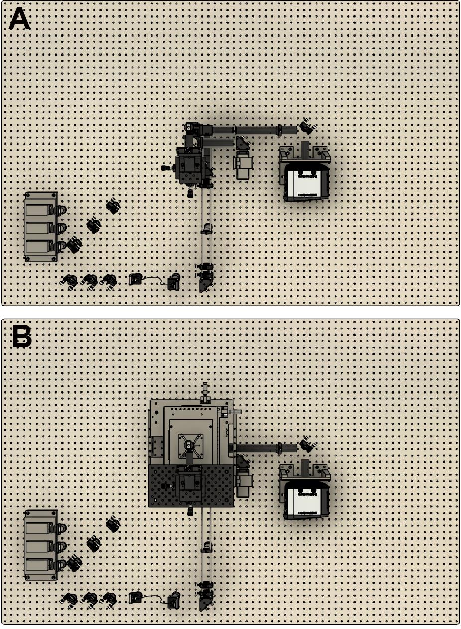
Figure 1. CAD design showing a top-down view of the optical assembly. A. Without the microscope frame. B. With the microscope frame.Next, lasers are placed onto a heat sink at the appropriate height. Currently, we use Vortran lasers (detailed in the components section) that can be purchased with clean-up filters to minimize extra components. Compact and simple designs have been previously described, for example by Nicovich et al. (2017). Links in the paper provide good guidelines on assembling the lasers (including designs) and useful resources including triggering and timing. Figure 2 below shows a close-up of the design that we implemented. Three lasers (405 nm, 488 nm, and 640 nm) are placed onto a heat sink, filtered using laser filters, and combined into a single line using dichroics. In practice, more lasers can be combined if necessary (e.g., 561 nm) by expanding the design. The lasers are then aligned into a fiber. Once installed, we expect ~70% coupling efficiency.
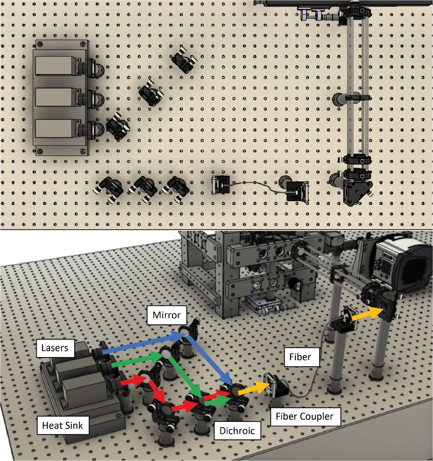
Figure 2. Laser assembly and fiber coupling. Three lasers (405 nm, 488 nm, and 640 nm) are placed onto a heat sink, combined using dichroics, and coupled to a laser fiber.Place the output of the optical fiber at the intended height of the expansion optics. Ensure that the laser output is straight and travels parallel to the table without deviating.
Set up the laser expansion cage assembly (cage rods, ×2 right-angle mirror mounts, and ×3 cage XY translation mounts) attached to a custom RM21 bracket frame (https://github.com/spcoelho/Active-Stabilization-Design) and place at the required height. We recommend using steel pedestals to ensure greater stability. Figure 3 illustrates the assembly.
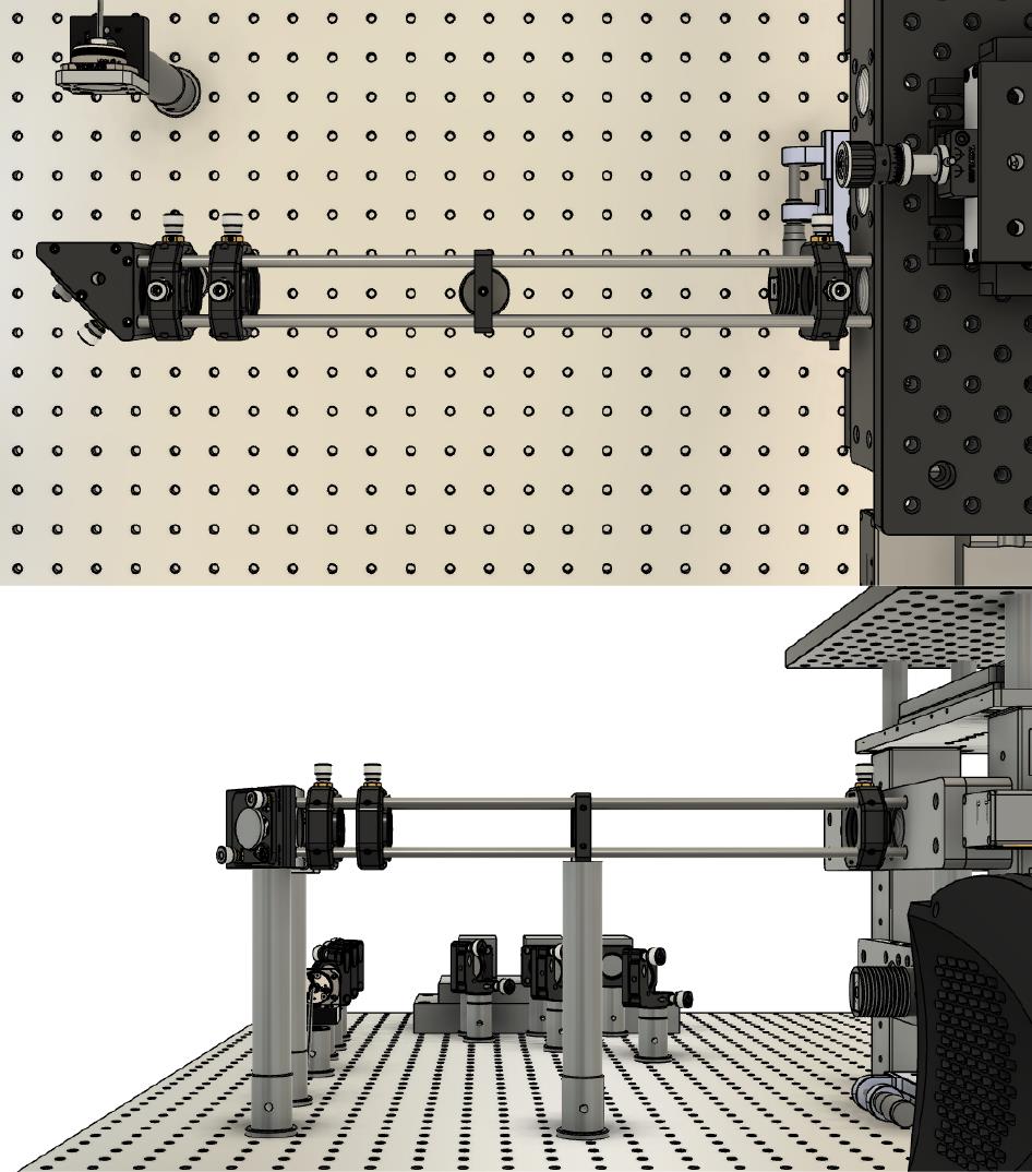
Figure 3. Assembly of the laser expansionAlign the laser so that it is centered throughout the cage assembly.
Place the lenses to provide ~10-fold expansion of the laser (e.g., 30 mm and 300 mm). Ensure that these are placed at the correct distance from each other using a Shearing Interferometer.
Assemble the mirror and tube lens (200 mm focal length) on top of the translation stage. The translation stage moves the lens and mirror assembly together. Ensure that the reflected beam is straight and parallel to the optical table. Place the mirror/lens centered within the frame of the microscope.
Take the dichroic holders (×2) and attach to each other. Place below the position of the imaging objective at the height of the laser.
Attach the dichroics, via cage rods, to the microscope frame using the RM21 bracket (https://github.com/spcoelho/Active-Stabilization-Design) (Figure 4, left hand side and Figure 5).
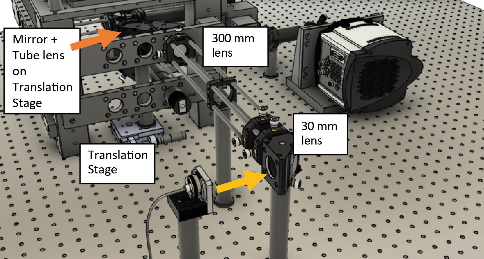
Figure 4. Mirror and tube lens are on top of a translation stage located within the microscope frame shown within the final assembly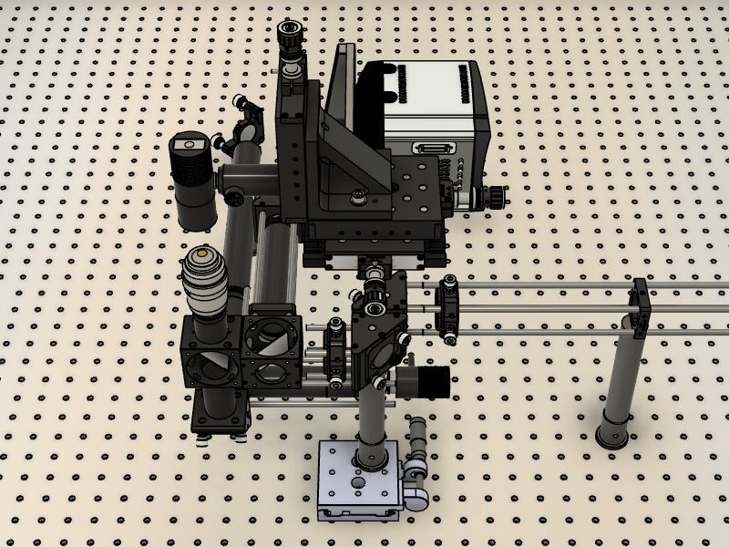
Figure 5. Internal components without the microscope body framePlace the dichroics within their holders. One dichroic is used to reflect the laser toward the sample/objective; the second dichroic is used to separate the infrared light for active stabilization. For more details on how to assemble and configure, please refer to Coelho et al. (2020b).
Align the laser so that it is centered onto the back of the imaging objective. A simple method consists of replacing the objective for a Frosted Glass Alignment Disk and observing the position of the laser.
To ensure that the tube lens is at the correct distance from the back of the objective, the laser output should be as small as possible after exiting the objective. While observing the laser profile at a large distance (e.g., ceiling), adjust the position of the tube lens to ensure that a Gaussian beam with minimal diameter exits the objective. Misalignments can lead to a distorted beam profile (e.g., astigmatic).
Assemble the Infrared Camera/LED Path
Assemble the cage system (cage rods, right angle mirror mount, and 200 mm infrared lens) and attach it to the dichroic cube (Figure 6).
Secure to the microscope frame using an RM21 bracket (https://github.com/spcoelho/Active-Stabilization-Design).
Attach the infrared camera using an SM1 adapter and connect to a PC.
Assemble the infrared LED, place on the XYZ translation stage, and align onto the infrared camera [for more details, see Coelho et al. (2020b)].
Turn on the infrared LED and check that the illumination is centered and uniform on the infrared camera.
Place polystyrene beads on the glass coverslip and record their diffraction rings.
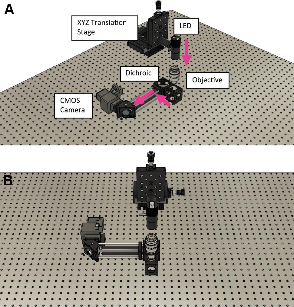
Figure 6. Assembly of the cage system to secure the infrared camera. The components are shown in relation to the infrared LED without the brackets/microscope frame. A. Front view. B. 45° view.
Detection (Emission camera and camera stabilization path)
This section describes how to introduce an optical feedback loop for the emission path (Figure 7). This allows to correct for movement in the detection path, facilitating high stability for prolonged acquisitions.
Emission Camera
To direct the fluorescence from the sample toward the camera, attach a right-angle mirror mount to tubing and connect it to the bottom of the laser dichroic holder (Figure 7).
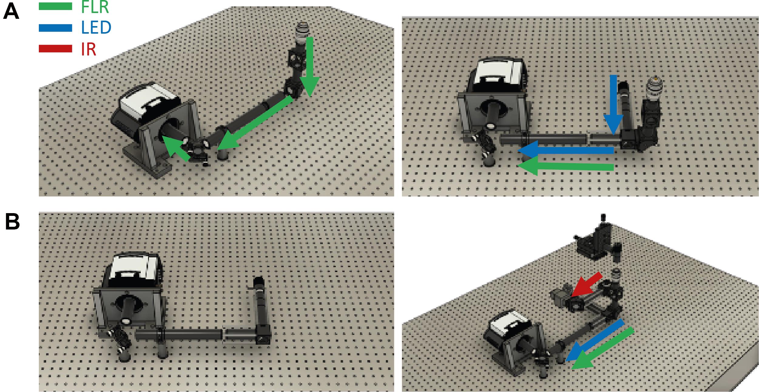
Figure 7. Assembly of the fluorescence emission path. A. Left: Without the white LED. Right: With the white LED. B. Left: Only the camera stabilization path. Right: Detection assembly in relation to the infrared detection.Adjust the length of the tube to match the predicted height of the fluorescent camera.
Within the tube, insert the emission filter (Em01-R405/488/635-25; Semrock). This removes the laser light and/or infrared LED.
Attach the tube lens (e.g., 400 mm focal length).
For the white LED: Attach the cage cube to the free side of the right-angle mirror mount.
Note: If extra distance between the camera and the tube lens is required, add a pair of relay lenses (e.g., 2 × 50 mm).
Secure the assembly to the RM21 microscope frame using cage rods and/or SM1 tubing.
Attach the camera to an optical table at the correct distance away from the lens.
Place a mirror (or piezo-electric mirror) in front of the camera.
Adjust the focal length of the tube lens. A simple way to get the correct distance is to flip the laser dichroic so that it reflects toward the camera. Using a very low laser power and multiple neutral density filters, focus the laser onto the camera. To get the correct distance, also remove the laser filter and last lens in the laser excitation path (TIRF lens mounted on the translation stage).
Place a uniform fluorescent sample (fluorescent molecules in solution or fluorescent marker) and check the emission onto the camera.
Center the emission onto the camera using the elliptical mirror underneath the objective lens. The emission should be uniform across the recorded field-of-view.
Camera Stabilization
Attach the white LED to the microscope frame (Figures 4 and 7B left).
Assemble the cage/tube system containing a pinhole (diameter = 50 µm) and lens (e.g., f = 400 mm).
Center the pinhole and adjust the position of the lens to ensure a bright Gaussian spot focused on the camera.
Position the white LED spot on the edge of the imaging field-of-view (Figure 8).
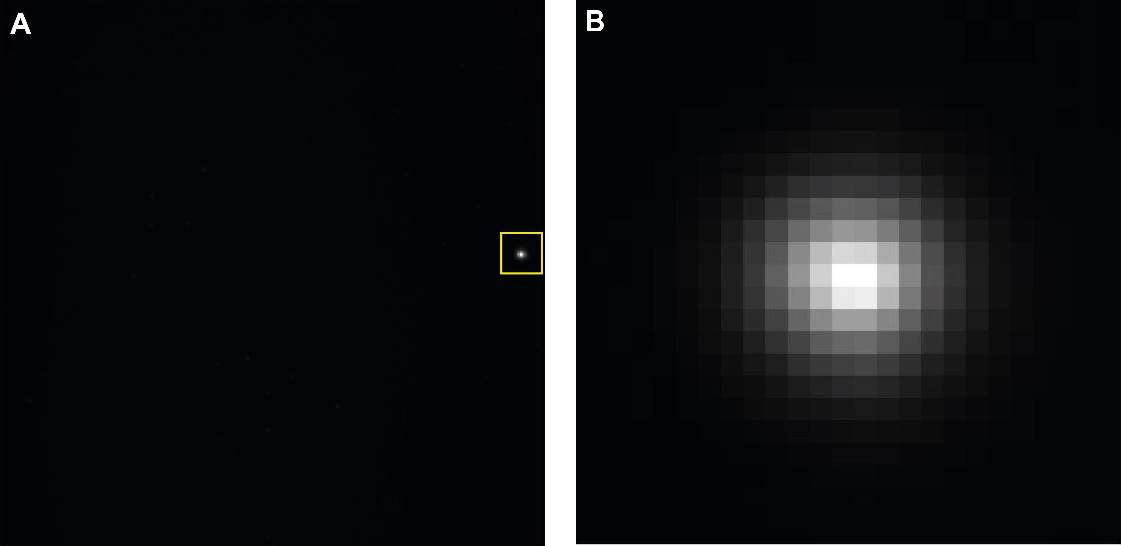
Figure 8. Camera stabilization. A. Full camera image showing LED projection toward the edge chip. B. Zoomed in region highlighted in the yellow square.
Acknowledgments
We are thankful for support from the Australia Research Council (CE140100011 to K.G., FL150100060 and CE140100036 to J.J.G.) and the National Health and Medical Research Council of Australia (APP1059278 to K.G.). This protocol is based on previous work, mainly from Coelho et al. (2020a).
Competing interests
The authors declare no competing financial interests.
References
- Axelrod, D. (2001). Total Internal Reflection Fluorescence Microscopy in Cell Biology. Traffic 2(11): 764-774.
- Aoki, K. and Matsuda, M. (2009). Visualization of small GTPase activity with fluorescence resonance energy transfer-based biosensors. Nat Protoc 4(11): 1623.
- Baek, J., Loua, J., Coelhoa, S., Lim, D., Seidlitz S., Nicovich, P. R., Gaus, K. (2017).Imaging galectin-3 dependent endocytosis with lattice light-sheet microscopy. International Conference on Biophotonics V 10340: SPIE.
- Boutros, M., Heigwer, F. and Laufer. C. (2015). Microscopy-Based High-Content Screening. Cell 163(6): 1314-1325.
- Burke, D., Patton, B., Huang, F., Bewersdorf, J. and Booth M.J. (2015).Adaptive optics correction of specimen-induced aberrations in single-molecule switching microscopy. Optica 2(2): 177-185.
- Coelho, S., Baek, J., Graus, M.S., Halstead, J.M., Nicovich, P.R., Feher, K., Gandhi, H., Gooding, J.J. and Gaus, K. (2020a). Ultraprecise single-molecule localization microscopy enables in situ distance measurements in intact cells. Sci Adv 6(16): eaay8271.
- Coelho, S., Baek, J., Walsh, J., Gooding, J.J. and Gaus, K. (2020b). 3D active stabilization for single-molecule imaging. Nat Protoc16(1): 497-515.
- Coelho, S., Poland, S., Krstajic, N., Li, D., Monypenny, J., Walker, R., Tyndall, D., Ng, T., Henderson, R. and Ameer-Beg, S. (2013). Multifocal multiphoton microscopy with adaptive optical correction. Progress in Biomedical Optics and Imaging - Proceedings of SPIE 8588: 17. 2013: SPIE.
- Coelho, S., Coelho, S., Poland, S.P., Devauges, V. and Ameer-Beg, S.M.(2020c). Adaptive optics for a time-resolved Förster resonance energy transfer (FRET) and fluorescence lifetime imaging microscopy (FLIM) in vivo.Opt Lett 45(10): 2732-2735.
- Diekmann, R., Helle, Ø.I., Øie C.I., McCourt, P., Huser, T.R., Schüttpelz, M. and Ahluwalia, B. S. (2017). Chip-based wide field-of-view nanoscopy. Nat Photon 11(5): 322-328.
- Eggeling, C., Ringemann, C., Medda, R., Schwarzmann, G., Sandhoff, K., Polyakova, S., Belov, V.N., Hein, B., von Middendorff, C., Schönle, A. and Hell, S.W. (2009). Direct observation of the nanoscale dynamics of membrane lipids in a living cell.Nature 457(7233): 1159-1162.
- Fish, K. N. (2009).Total internal reflection fluorescence (TIRF) microscopy. Curr Protoc Cytom Chapter 12: Unit12.18.
- Gao, L., Shao, L., Chen, B.C. and Betzig, E. (2014).3D live fluorescence imaging of cellular dynamics using Bessel beam plane illumination microscopy. Nat Protoc 9(5): 1083-1101.
- Giessibl, F.J., Advances in atomic force microscopy. (2003). Rev Mod Phys 75(3): 949.
- Gustavsson, A.K., Petrov, P.N., Lee, M.Y., Shechtman, Y. and Moerner, W.E.(2018). 3D single-molecule super-resolution microscopy with a tilted light sheet.Nat Commun 9(1): 1-8.
- Huang, B., Wang, W., Bates, M. and Zhuang, X. (2008). Three-Dimensional Super-Resolution Imaging by Stochastic Optical Reconstruction Microscopy. Science 319(5864): 810-813.
- Huang, F., Sirinakis, G., Allgeyer, E.S., Schroeder, L.K., Duim, W.C., Kromann, E.B., Phan, T., Rivera-Molina, F.E., Myers, J.R., Irnov, I., Lessard, M., Zhang, Y., Handel, M.A., Jacobs-Wagner, C., Lusk, C.P., Rothman, J.E., Toomre, D., Booth, M.J. and Bewersdorf, J. (2016). Ultra-High Resolution 3D Imaging of Whole Cells. Cell166(4): 1028-1040.
- Kim, J., Park, B.W., Baek, J., Yun, J.S., Kwon, H.W., Seidel, J., Min, H., Coelho, S., Lim, S., Huang, S., Gaus, K., Green, M.A., Shin, T.J., Ho-Baillie, A.W.Y., Kim, M.G. and Seok, S.I. (2020). Unveiling the relationship between the perovskite precursor solution and the resulting device performance. J Am Chem Soc 142(13): 6251-6260.
- Krstajić, N., Poland, S., Tyndall, D., Walker, R., Coelho, S., Li, D.D.U., Richardson, J., Ameer-Beg, S. and Henderson, R. (2013). Improving TCSPC data acquisition from CMOS SPAD arrays in European Conference on Biomedical Optics. Optical Society of America paper: 879709.
- Jungmann, R., Avendaño, M.S., Woehrstein, J.B., Dai, M., Shih, W.M. and Yin, P. (2014). Multiplexed 3D cellular super-resolution imaging with DNA-PAINT and Exchange-PAINT. Nat Methods11(3): 313-318.
- Nicovich, P.R., Walsh, J., Böcking, T. and Gaus, K.(2017). NicoLase-an open-source diode laser combiner, fiber launch, and sequencing controller for fluorescence microscopy. PLoS One 12(3): e0173879.
- Pavani, S.R., Thompson, M.A., Biteen, J.S., Lord, S.J., Liu, N., Twieg, R.J., Piestun, R. and Moerner, W.E. (2009) Three-dimensional, single-molecule fluorescence imaging beyond the diffraction limit by using a double-helix point spread function. Proc Natl Acad Sci U S A 106(9): 2995-2999.
- Poland, S.P., Krstajić, N., Monypenny, J., Coelho, S., Tyndall, D., Walker, R.J., Devauges, V., Richardson, J., Dutton, N., Barber, P., Li, D.D., Suhling, K., Ng, T., Henderson, R.K. and Ameer-Beg, S.M. (2015).A high speed multifocal multiphoton fluorescence lifetime imaging microscope for live-cell FRET imaging. Biomed Opt Express 6(2): 277-296.
- Poland, S.P., Krstajić, N,, Coelho, S., Tyndall, D., Walker, R.J., Devauges, V., Morton, P.E., Nicholas, N.S., Richardson, J., Li, D.D., Suhling, K., Wells, C.M., Parsons, M., Henderson, R.K. and Ameer-Beg, S.M. (2014). Time-resolved multifocal multiphoton microscope for high speed FRET imaging in vivo. Opt Lett 39(20): 6013-6016.
- Suhling, K., Hirvonen, L.M., Levitt, J.A., Chung, P.H., Tregidgo, C., Marois, A.L., Rusakov, D.A., Zheng, K., Ameer-Beg, S., Poland, S., Coelho, S., Henderson, R. and Nikola Krstajic. (2015) Fluorescence lifetime imaging (FLIM): Basic concepts and some recent developments. MedPhoton 27: 3-40.
- Suhling, K., et al. (2017). Fluorescence lifetime imaging. In: Handbook of Photonics for Biomedical Engineering. Springer: 353-405.
- Suhling, K., Hirvonen, L. M., Levitt, J.A., Chung, P.H., Tregido, C., Marois, A., Rusakov, D.A., Zheng, K., Ameer-Beg, S., Poland, S., Coelho, S. and Dimble, R. (2015). Fluorescence lifetime imaging (Flim): Basic concepts and recent applications, in Advanced Time-Correlated Single Photon Counting Applications. Springer Series in Chemical Physics 111:119-188.
- Schmidt, P.D., Reichert, B.H., Lajoie, J.G. and Sivasankar, S. (2018).Method for high frequency tracking and sub-nm sample stabilization in single molecule fluorescence microscopy. Sci Rep 8(1): 13912.
- Shechtman, Y., Sahl, S.J., Backer, A.S. and Moerner, W.E. (2014). Optimal point spread function design for 3D imaging. Phys Rev Lett 113(13): 133902.
- Shtengel, G., Galbraith, J.A., Galbraith, C.G., Lippincott-Schwartz, J., Gillette, J.M., Manley, S., Sougrat, R., Waterman, C.M., Kanchanawong, P., Davidson, M.W., Fetter, R.D. and Hess, H.F. (2009). Interferometric fluorescent super-resolution microscopy resolves 3D cellular ultrastructure. Proc Natl Acad Sci U S A 106(9): 3125-3130.
- Shroff, H., Galbraith, C.G., Galbraith, J.A. and Betzig, E. (2008). Live-cell photoactivated localization microscopy of nanoscale adhesion dynamics. Nat Methods 5(5): 417.
- Tokunaga, M., Imamoto, N. and Sakata-Sogawa, K. (2008). Highly inclined thin illumination enables clear single-molecule imaging in cells. Nat Methods 5(2): 159-161.
Article Information
Copyright
© 2021 The Authors; exclusive licensee Bio-protocol LLC.
How to cite
Readers should cite both the Bio-protocol article and the original research article where this protocol was used:
- Coelho, S., Baek, J., Gooding, J. J. and Gaus, K. (2021). Building a Total Internal Reflection Microscope (TIRF) with Active Stabilization (Feedback SMLM). Bio-protocol 11(13): e4074. DOI: 10.21769/BioProtoc.4074.
- Coelho, S., Baek, J., Graus, M.S., Halstead, J.M., Nicovich, P.R., Feher, K., Gandhi, H., Gooding, J.J. and Gaus, K. (2020). Ultraprecise single-molecule localization microscopy enables in situ distance measurements in intact cells. Sci Adv 6(16): eaay8271.
Category
Biological Engineering > Biomedical engineering
Biophysics > Microscopy
Do you have any questions about this protocol?
Post your question to gather feedback from the community. We will also invite the authors of this article to respond.