- Protocols

- Articles and Issues
- For Authors
- About
- Become a Reviewer

Rice Root Hair Phenotypes Imaged by Cryo-SEM

Published: Vol 11, Iss 11, Jun 5, 2021 DOI: 10.21769/BioProtoc.4037 Views: 5736
Reviewed by: Anonymous reviewer(s)
Original research article
The authors used this protocol in:
Jun 2011
Advertisement


Protocol Collections
Comprehensive collections of detailed, peer-reviewed protocols focusing on specific topics


Abstract
Cryo-scanning electron microscopy (cryo-SEM) was first introduced for scientific use in the 1980s. Since then, cryo-SEM has become a routine technique for studying the surfaces and internal structures of biological samples with a high water content. In contrast to traditional SEM, cryo-SEM requires no sample pretreatment processes; thus, we can obtain the most authentic images of the sample shape and structure. Cryo-SEM has two main steps: cryoprocessing of samples and scanning electron microscopy (SEM) observation. The cryoprocessing step includes preparation of the cooled slushing station, cooling of the preparation chamber, sample preparation, and sputtering. The sample is then transferred to an SEM cold stage for observation. We used cryo-SEM to study rice root hair tissues, but the methods and protocols can be applied to other root systems. This protocol optimizes the two key operation steps of reducing the humidity in the growth chamber and previewing the samples before sputtering and can more quickly obtain high-quality images.
Keywords: Cryo-SEMBackground
Scanning electron microscopy (SEM) refers to the use of an electron beam apparatus and a pattern inspection apparatus to image a sample surface (Yan, 2010). The first SEM came on the market in 1965 when the Cambridge Instrument Company launched a commercial instrument (McMullan, 1995). Specifically, biological samples must be dehydrated before entering the SEM chamber (Echlin, 1971), otherwise water vapor contaminates the electron microscope vacuum system. Before cryopreservation was invented, freeze-drying and critical point drying were two commonly used methods (Sargent, 1986). These pretreatments were inevitably associated with sample distortion, shrinkage, or loss of inner cellular soluble components (Reference 1; Echlin, 1971); additionally, they were time-consuming and laborious.
The water in a biological material generally forms ice crystals when the sample freezes at 0°C or below; however, the water forms a glasslike structure when the material is cooled at a very high cooling rate (Rey, 1960; Binder, 2014; Limmer and Chandler, 2014). In comparison with the crystal structure, this glasslike, amorphous water minimizes damage to the cell structure and mechanical properties (Vega-Gálvez et al., 2008); therefore, cryo-scanning electron microscopy (cryo-SEM) was devised to exploit this advantage.
An exceptional paper presented a detailed and comprehensive description of cryo-SEM development and its application in biology (Read and Jeffree, 1991). In short, cryo-SEM was first performed in 1960 but was not widely known until 1970 (Echlin, 1971). Commercial cryopreparation systems were available for SEMs in the 1980s; henceforth, cryo-SEM technology became routine and was commonly used in biological research (Read and Jeffree, 1991). Additionally, cryo-SEM was widely used in the field of botany for observations of the surface or freeze-etched fractions of roots (Vartanian et al., 1983; Webb and Jackson, 1986; Ryan et al.,1998; Dolan et al., 1994; Foreman and Dolan, 2001; Müller and Schmidt, 2004; Ding et al., 2009; Yi et al., 2010; Zhiming et al., 2011; Huang et al., 2013; Zou et al., 2015; Giri et al., 2018; Wang et al., 2019; Zenone et al., 2020), stems (Echlin, 1971), vessels (Utsumi et al., 1998), leaves (Sargent, 1983), shoot apexes (Kaneko, 1985), glandular trichomes (Kaneko, 1985), stamen hair cells (Kaneko, 1985), stigmas (Kaneko, 1985), petals (Wang et al., 2019), pollen grains (Echlin, 1971; Berger et al., 1998), stomatal pores (Echlin, 1971), berry skins (Brizzolara et al., 2020), seeds (Yu et al., 2014), etc. Moreover, cryo-SEM has been applied to the visualization of root-fungal interactions (Refshauge et al., 2006).
Root hairs are a type of tubular protuberant cell that diverges from specific root epidermal cells (Ishida et al., 2008; Kim and Dolan, 2016). They are capable of increasing root and soil contact areas and improving the efficiency of water and nutrient absorption while providing a place for the plant to interact with soil microorganisms (Larkin et al., 2003).
Without cryo-SEM, it is difficult to obtain favorable results for root hairs because of the large proportion of water inside root hairs. Root hair shape maintenance is dependent on turgor pressure driven by inner water (Mendrinna and Persson, 2015). Essentially, some samples, such as primary roots (Lefebvre, 1985), leaves (Eveling and McCall, 1983; Sargent, 1983), petals (Chen and Meyerowitz, 1999), and stamens (Chen and Meyerowitz, 1999), can remain intact after drying treatment and be photographed by SEM.
Nevertheless, with effective cryo-SEM technology, root hairs inevitably shrink and/or bend during cryo-preparation (Dolan et al., 1994; Czarnota et al., 2003; Cocozza et al., 2008; Zou et al., 2015); therefore, the process of preparing cryo-SEM samples is extremely important. In the following sections, some operations are highlighted and introduced in detail. In the foreseeable future, this technology will be suitable for stamen filament samples and other samples similar to root hair.
Advantages of Cryo-SEM:
It is suitable for tissue samples with a high moisture content.
Samples do not need to be fixed or dehydrated in advance.
It is proficient at revealing details that optical microscopy cannot.
Detailed quantitative parameters of the root hairs can be obtained.
The interior cell structure can be studied.
Disadvantages of Cryo-SEM:
Rice roots must be cultured in an agar plate.
Root sample throughput is fairly low as compared with other methods.
Sample pretreatment requires professional operation skills.
Price of sample pretreatment is relatively high.
Materials and Reagents
3MTM MicroporeTM Surgical Tape (3M, catalog number: 1533)
Nitrocellulose membranes with 0.8 μm pore size, 25 mm filter diameter (AAWG02500, Millipore, Gemany)
Rice root hair mutant Osbhlh115 seeds (Ding et al., 2009); Oryza sativa L. Xian group (also known as Hsien or Indica) wild-type Kathalath seeds
Sodium hypochlorite (BBI Life Sciences Corporation, China)
70% ethyl alcohol (BBI Life Sciences Corporation, China)
Murashige and Skoog Basal Medium (Duchefa Biochemie, catalog number: M0221)
Phytagel (Sigma-Aldrich, catalog number: P8169-250G)
Carbon-rich conductive glue (Rave Scientific, catalog number: RS-MN-15-001130)
Gold wafer (70-AU2408, 24 × 0.2 mm, purity 99.99%. Au, Labtech, UK)
Argon gas (99.99% purification, Hangzhou Jingong, China)
Nitrogen gas (99.99% purification, Hangzhou Jingong, China)
Liquid nitrogen (Hangzhou Jingong, China)
Equipment
Horizontal shaker (Beyotime, model: TS-2000A)
Growth chamber (Ningbo-Jiangnan, model: GXM-1008)
Scanning electron microscope (HITACHI, model: S-3000N)
GATAN ALTO 2100 (GATAN, model: ALTO 2100)
HITACHI SEM equipped with a GATAN cryo-SEM preparation system
Software
ImageJ (Version 1.53e, National Institutes of Health, United States, https://imagej.nih.gov/ij)
Office 365 (Microsoft, United States, https://www.office.com/)
Procedure
Rice Root Hair Growth
Sterilize the glume removed-rice seeds with 70% EtOH for 2 min, and remove the disinfectant alcohol. Then, sterilize the seeds with 10% sodium hypochlorite for 30 min on a horizontal shaker. Rinse the seeds thoroughly 5 times with sterile distilled water.
Place the seeds on sterile absorbent paper for drying.
Sow the seeds onto 0.8% phytagel half-strength MS medium (pH = 5.8).
Note: To avoid too much moisture attached to the root hairs, it is highly recommended to seal the medium plates with 3M Micropore surgical tape.
Place the medium plate vertically in the growth chamber under a temperature regime of 30°C/22°C (day/night) with 50% or lower humidity and a 12 h photoperiod (15,000 lux).
Note: Lowering the humidity is an effective way to reduce the moisture in the plate.
Use three-day-old rice roots after germination for subsequent sample treatment.
Preparation for Cryo-SEM
Install the SEM stage cold module (Figures 1; see Video 1).
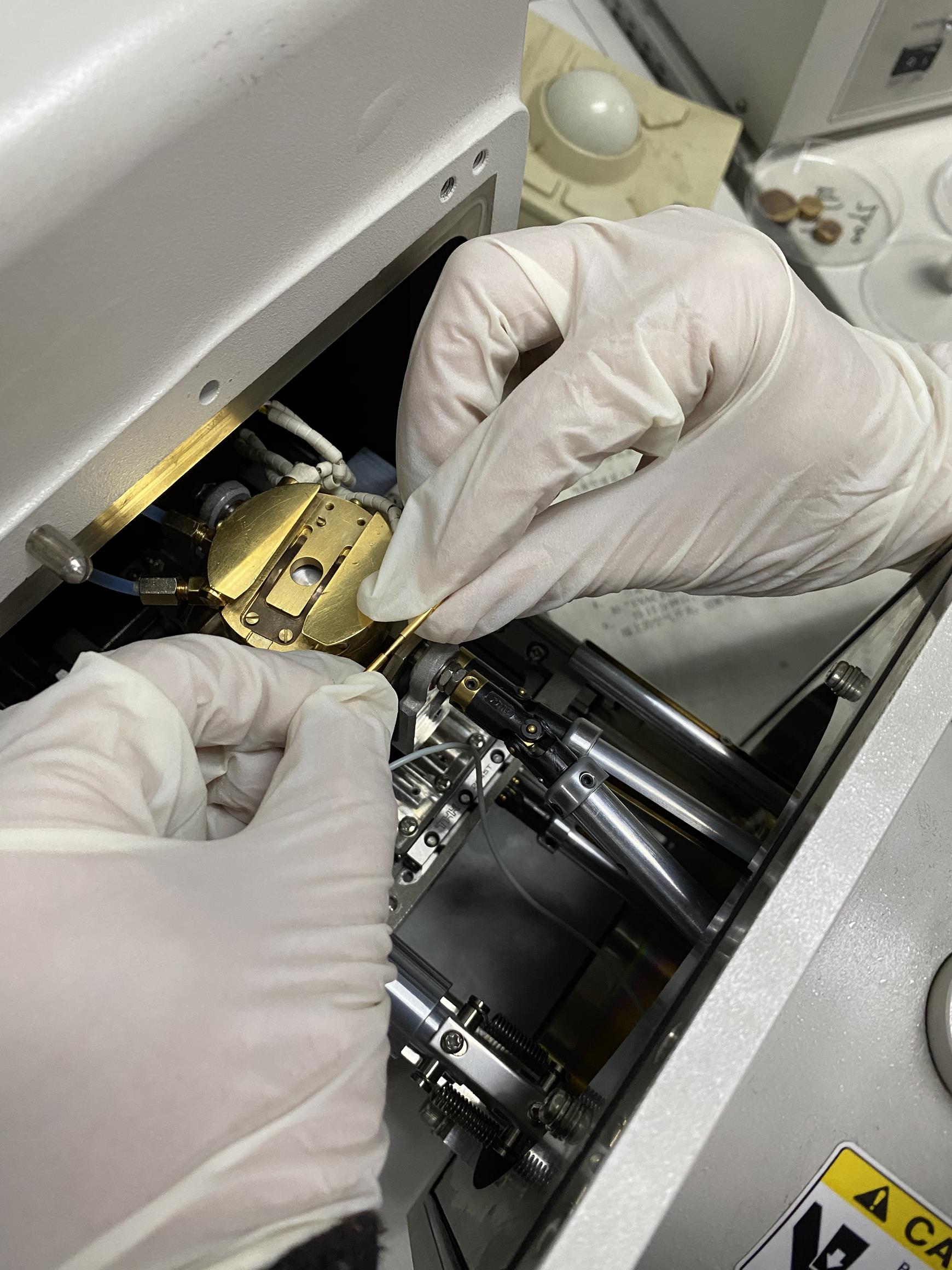
Figure 1. SEM stage cold module installation. Dovetail and fit the module with a thermometer. Push the copper shaft and copper shaft sleeve together to make an interference fit connection. Ensure that the real-time module temperatures are displayed on the keypad. Video 1. SEM stage cold module installation
Check the Alto 2100 keypad (or control panel) (Figure 2).
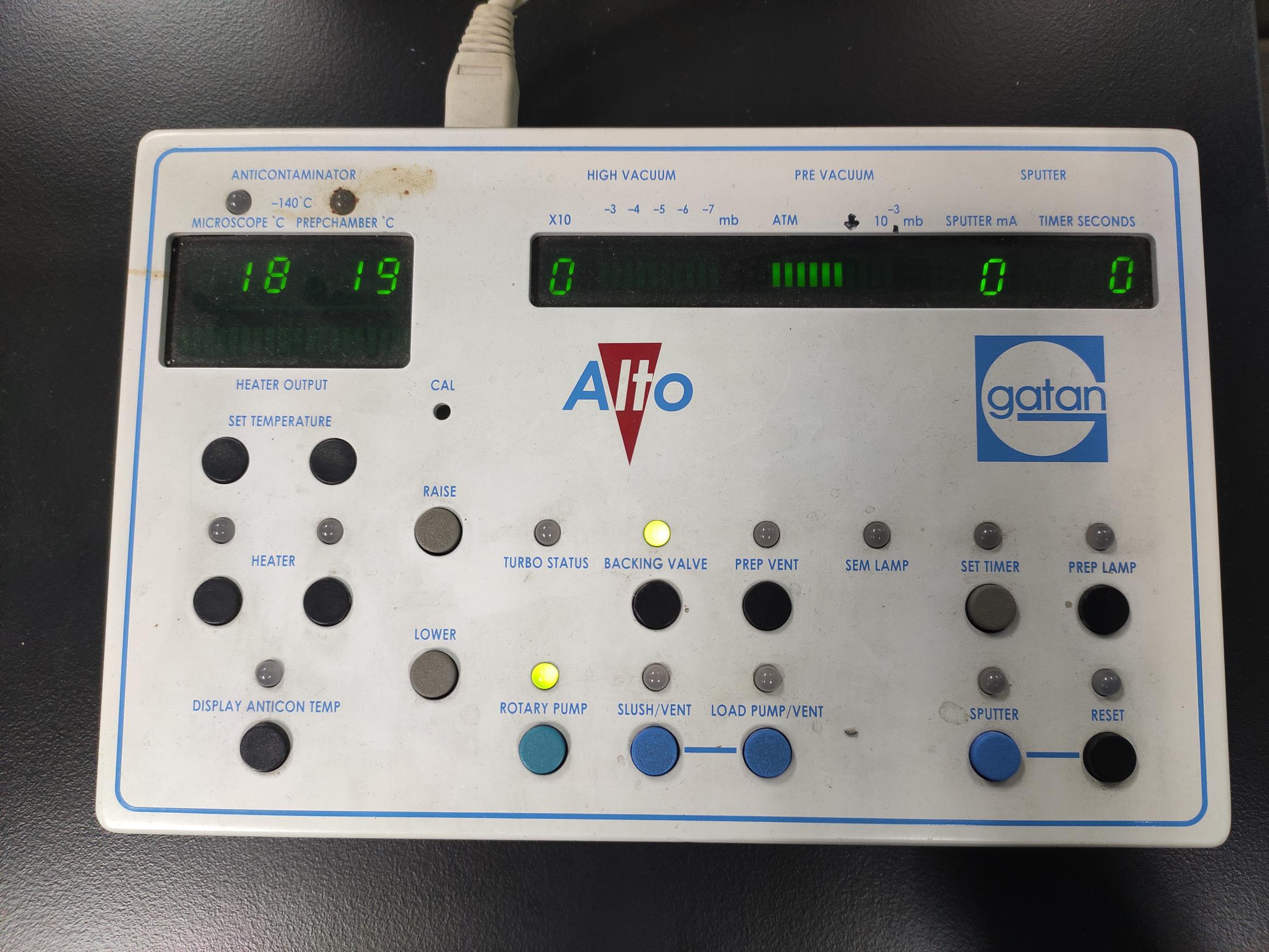
Figure 2. The keypad at the very beginning of the start-up. The keypad allows control of the pump and the system’s valves, sputter coater, lighting, and heater. All temperature and pressure readings are instantly available and easy to observe on the keypad.Prep chamber precooling (Figure 3, see Video 2)
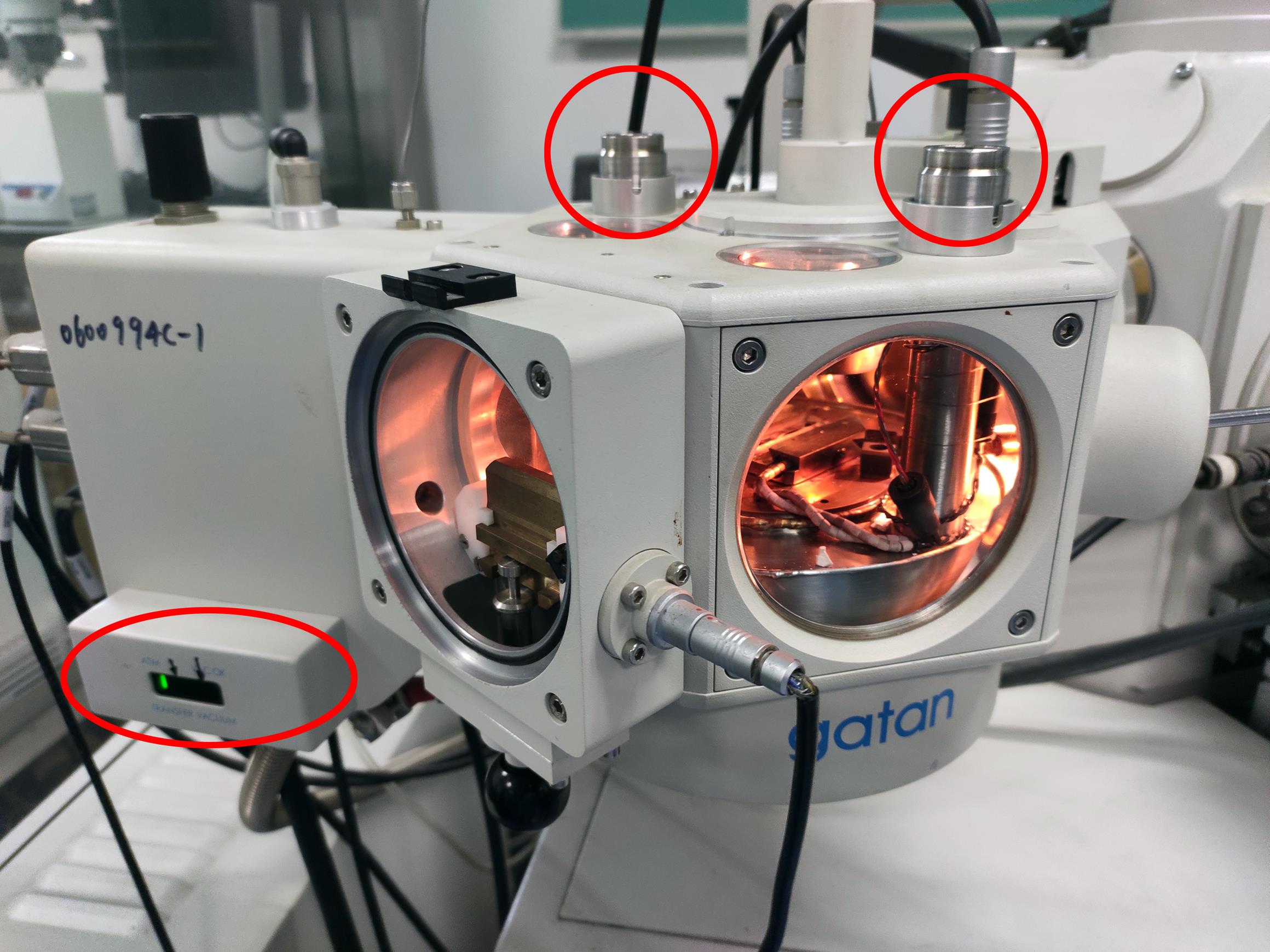
Figure 3. The prep-chamber before adding liquid nitrogen. The red circles indicate the inlet and outlet for liquid nitrogen. The red ellipse indicates the pressure indicator LED display. Video 2. Pour the liquid nitrogen into the prep chamber inletPrecool the SEM cold stage module
Pour liquid nitrogen into the open topped dewar where the pipeline is immersed (see Video 3). The pipeline is filled with high-purity nitrogen gas. The cooled gas in the pipeline cools down the SEM stage cold module below -180°C.
Video 3. Pour liquid nitrogen into the open topped dewarNote: Ventilate the cryo-pipeline for at least 5 min before running the cryo-SEM system. A uniform flow rate of nitrogen in the pipeline is necessary for image quality.
Produce slush nitrogen
Pour the liquid nitrogen into the slush chamber and close the lid (see Video 4).
Note: Wear waterproof cryogloves!
Video 4. Preparation of slush nitrogenPress the SLUSH/VENT button on the Alto control panel to activate slush chamber pumping (see Video 4).
Allow the liquid nitrogen to boil until it solidifies. This step takes approximately two minutes.
Press the SLUSH/VENT button again to stop pumping and vent the air into the chamber.
Remove the lid before use.
Root Sample Acquisition
Cut a 1-2 cm length of wild type or mutant straight growing seminal roots for use.
Add a drop of carbon-rich conductive glue to the aluminum stub of the specimen holder (see Video 5).
Video 5. The conductive glue was applied to the aluminum stubPlace a piece of moist nitrocellulose paper, immersed in distilled water in advance, on the glue (see Video 6).
Video 6. Putting the nitrocellulose paper onto the sample stage and applying gelGently clamp the cut-off root end with tweezers and transfer the root onto nitrocellulose paper. Place the root as horizontally as possible (Figure 4).
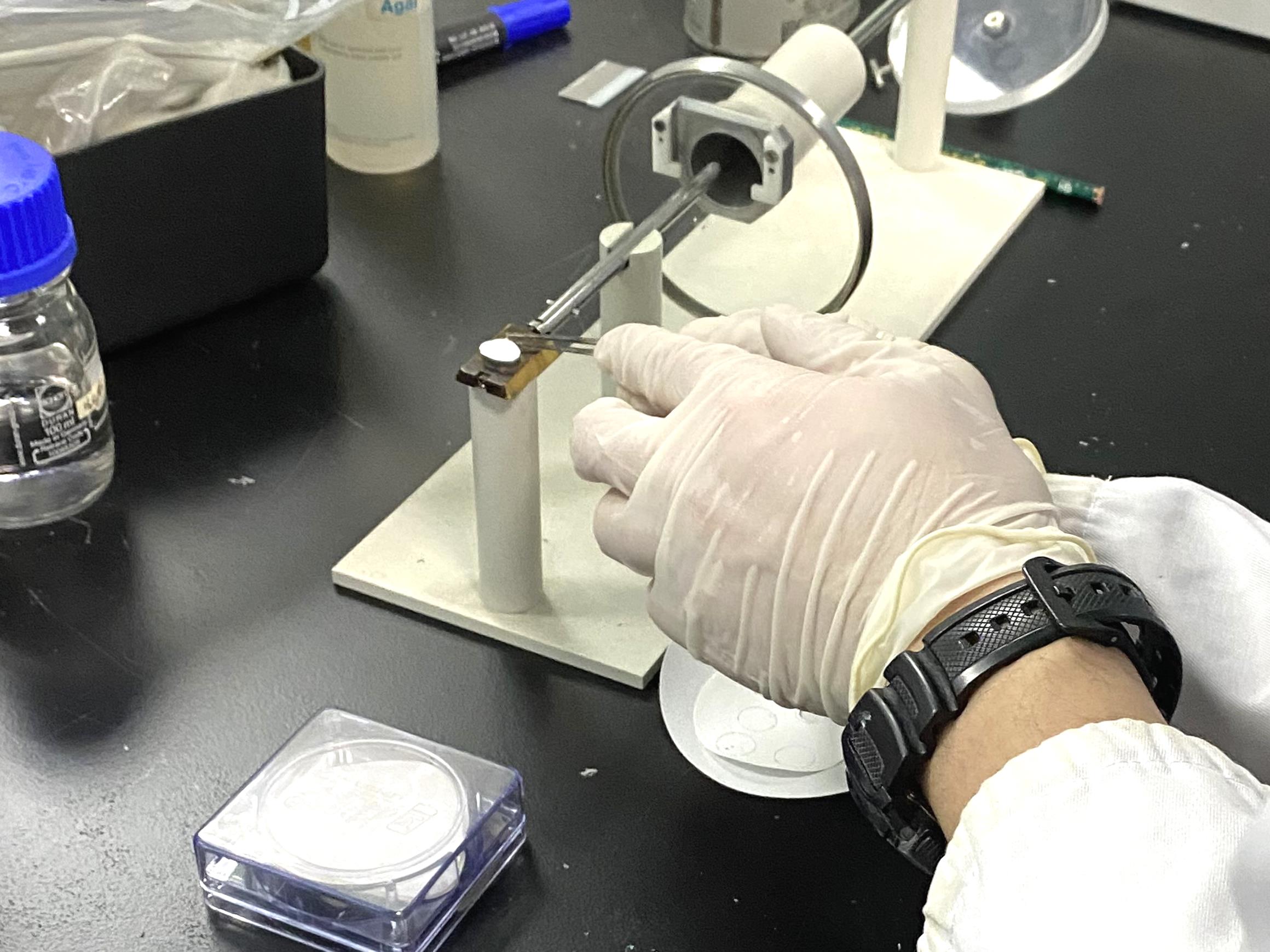
Figure 4. Clamping the rice root onto the nitrocellulose paper. First, apply conductive glue to the aluminum stub. Then, place the nitrocellulose paper on the gel. After that, spread the conductive glue to the near end of the rod. Last, stick the root cut end on the glue and lay the root flat on the nitrocellulose paper.Immerse the trimmed root end in the glue (Figure 4).
Root Sample Repreparation
Stick together the specimen holder with a root sample on its stub and the sample holder integrated with the vacuum transfer device (VTD) (see Video 7).
Buckle the sample holder (with the VTD) to the slush chamber until the VTD sits on the O-ring in the recess located on the top of the slushing chamber (see Video 7).
Slide the rod in the VTD down (see Video 7).
Grip the sample holder in the air above the nitrogen pool for 10 s to quickly freeze the root hair (see Video 7).
Plunge the sample holder into the slushy nitrogen to rapidly cool the sample (see Video 7).
Note: Ensure that only the sample holder is immersed in the nitrogen when slushing, otherwise the cold rod freezes the VTD’s O-ring. This has a negative influence on the subsequent push-pull operation and/or the gas tightness.
Video 7. The sample immersed into the nitrogen slushPress the SLUSH/VENT button to activate slush chamber pumping.
Pull the VTD rod upward and fully retract the sample holder into VTD before the nitrogen slush completely solidifies (see Video 8).
Video 8. The sample waiting to leave the slushing stationPush the trapdoor valve (see Video 9) (The sample is now held in the VTD under a vacuum and ready for transfer into the prep chamber).
Video 9. The sample leaving the slushing stationPress the SLUSH/VENT button once again to vent the slush chamber.
Transfer and place the VTD in the GATE VALVE airlock (see Video 10).
Video 10. Pump the Gate Value airlock vacuumPress the LOAD PUMP button on the Alto control panel to vacuum the prep chamber (Figure 2).
Wait until six bars of indicator light illuminate, which is indicated by the red ellipse in Figure 3.
Fully open the valve, push the rod, and insert the specimen holder into the dovetail stage in the prep chamber (Figures 5-6; see Video 11).
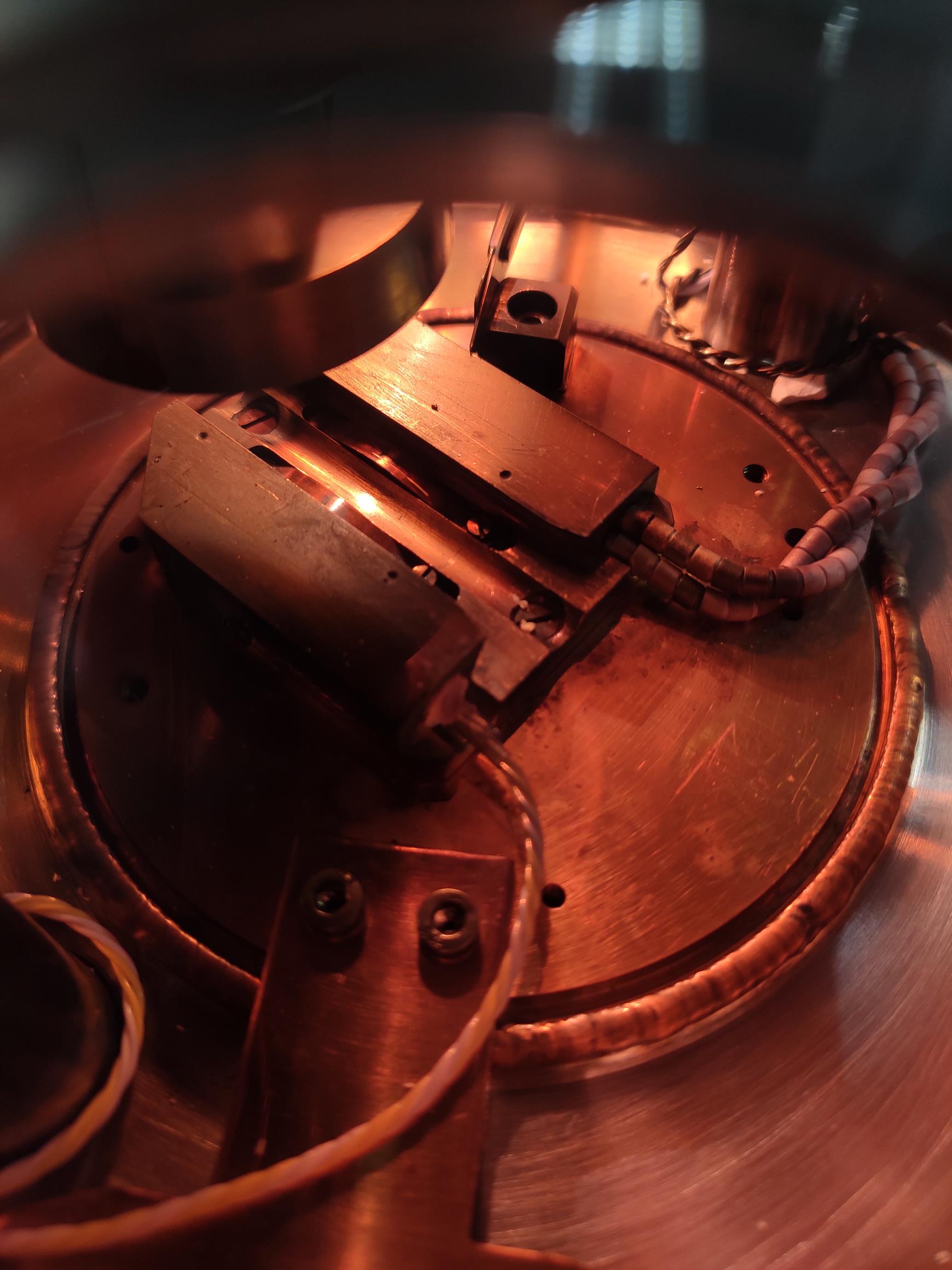
Figure 5. The dovetail stage in the prep-chamber. The dovetail stage is convenient for the angled sides of the sample holders and is fitted with a thermometer and a heater. There is a stopper to allow the sample holder to be transferred to exactly the same position. A spring clip secures the holder and prevents vibration.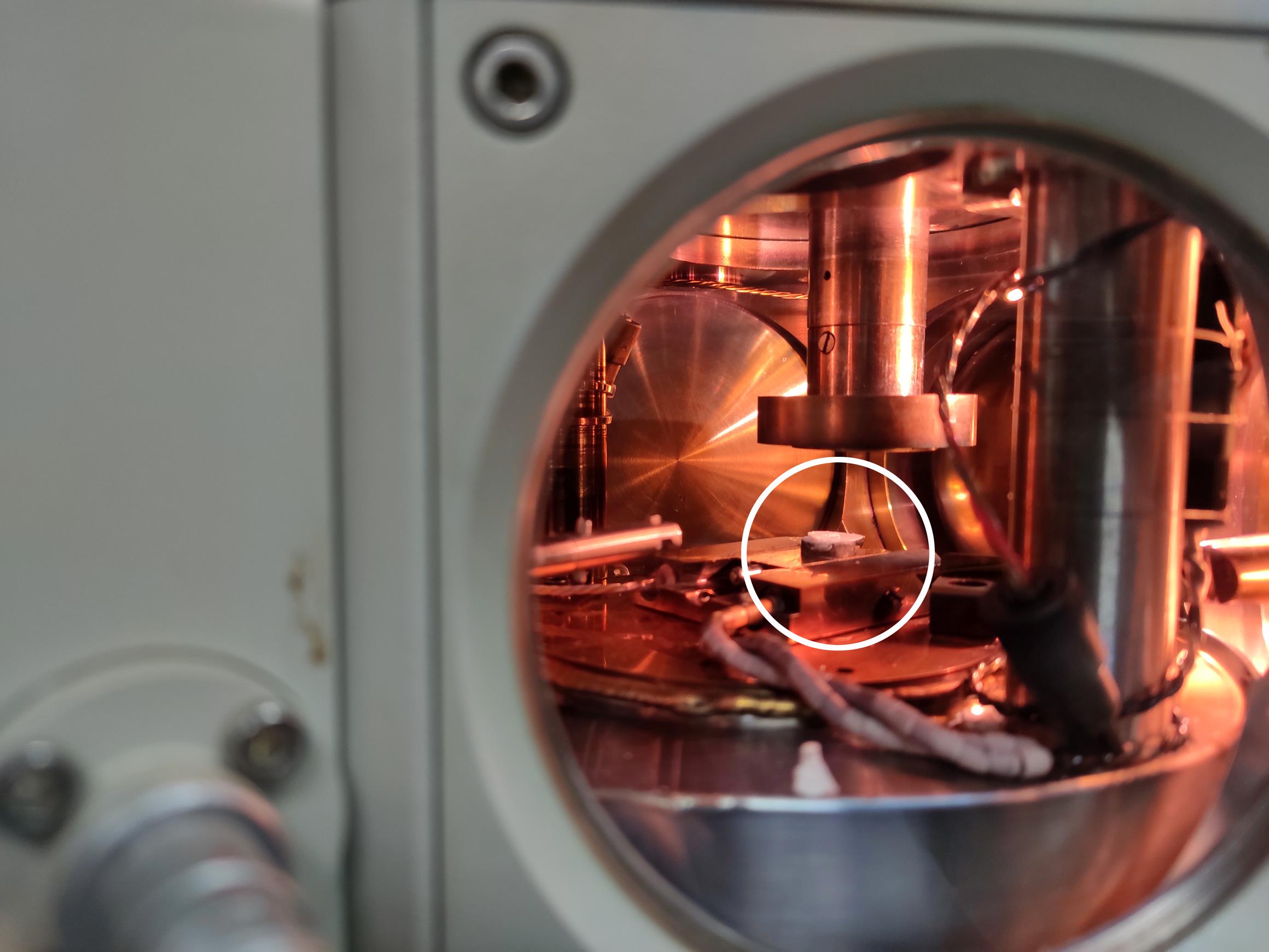
Figure 6. The rice root sample before sublimating and sputtering. The white circle indicates that the sample is waiting to be sublimated and sputtered on the stage. Video 11. Transfer the sample to the prep chamber (The VTD and prep chamber valves are opened simultaneously)Set the sublimation temperature of the prep-chamber stage to -95°C (Figure 7).
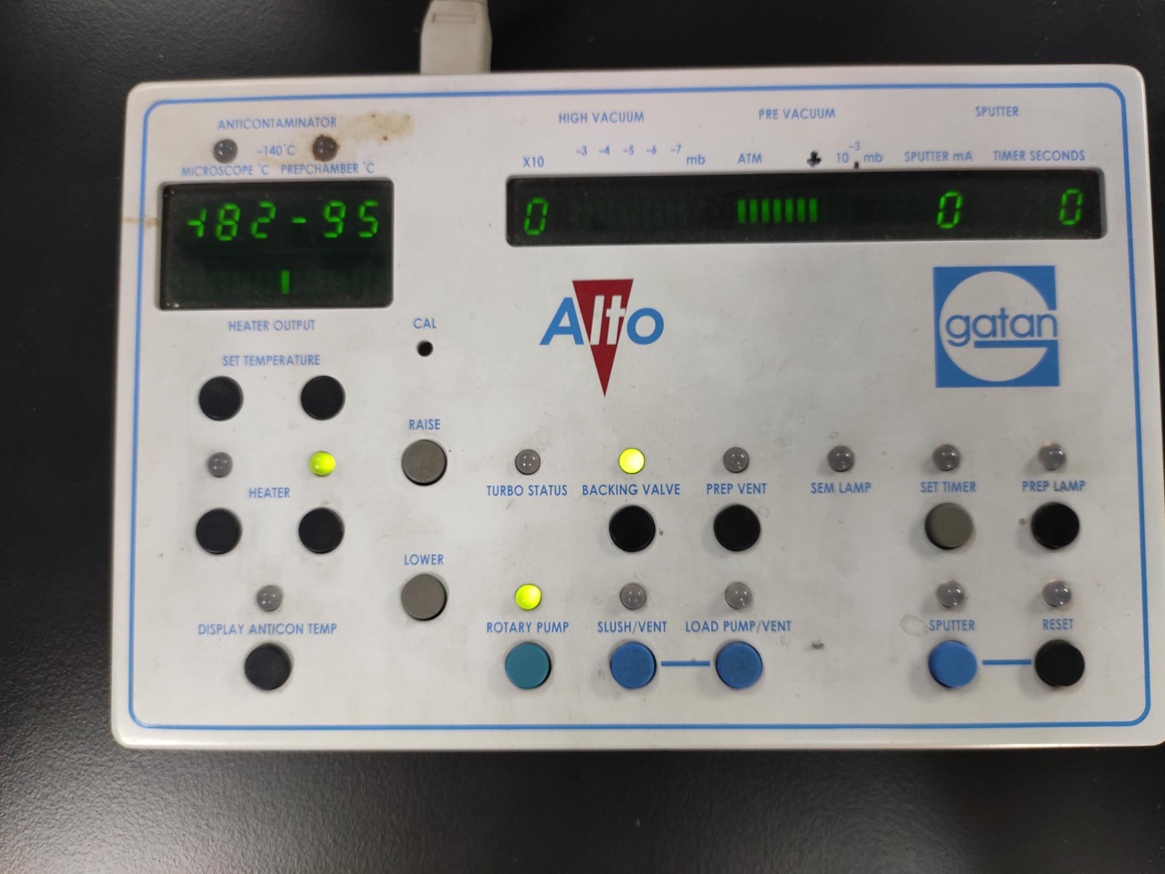
Figure 7. The sublimation temperature settings. By pressing the SET TEMPERATURE buttons, set the sublimation temperature to -95°C.Press the HEAT button to start warm-up (see Video 12) (For rice root hairs, maintaining at -95°C for 300 s is optimal. The sublimation time mainly depends on the humidity of the root culture environment).
Video 12. The sublimation temperature keeps risingPress the HEAT button again to stop heating and recover the temperature to ≤ -140°C.
Set the gold sputter time and press the SPUTTER button on the control panel (120 s is sufficient for root hairs) (Figure 8).
Note: If the prep chamber is not equipped with a microscope device, samples can be transferred to the SEM chamber for rough viewing before sputtering. This step is extremely important for obtaining favorable samples and high-quality images.
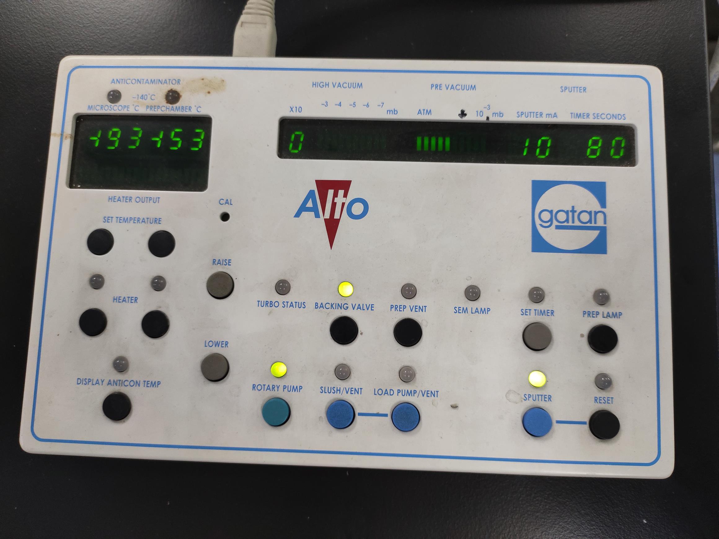
Figure 8. The sputter parameter display. The default setting of the sputter electric current is 10 mA. Before argon sputtering, the stage temperature should be cooled to ≤-140°C.The argon inlet solenoid closes automatically when the time is up (Figure 9; see Video 13).
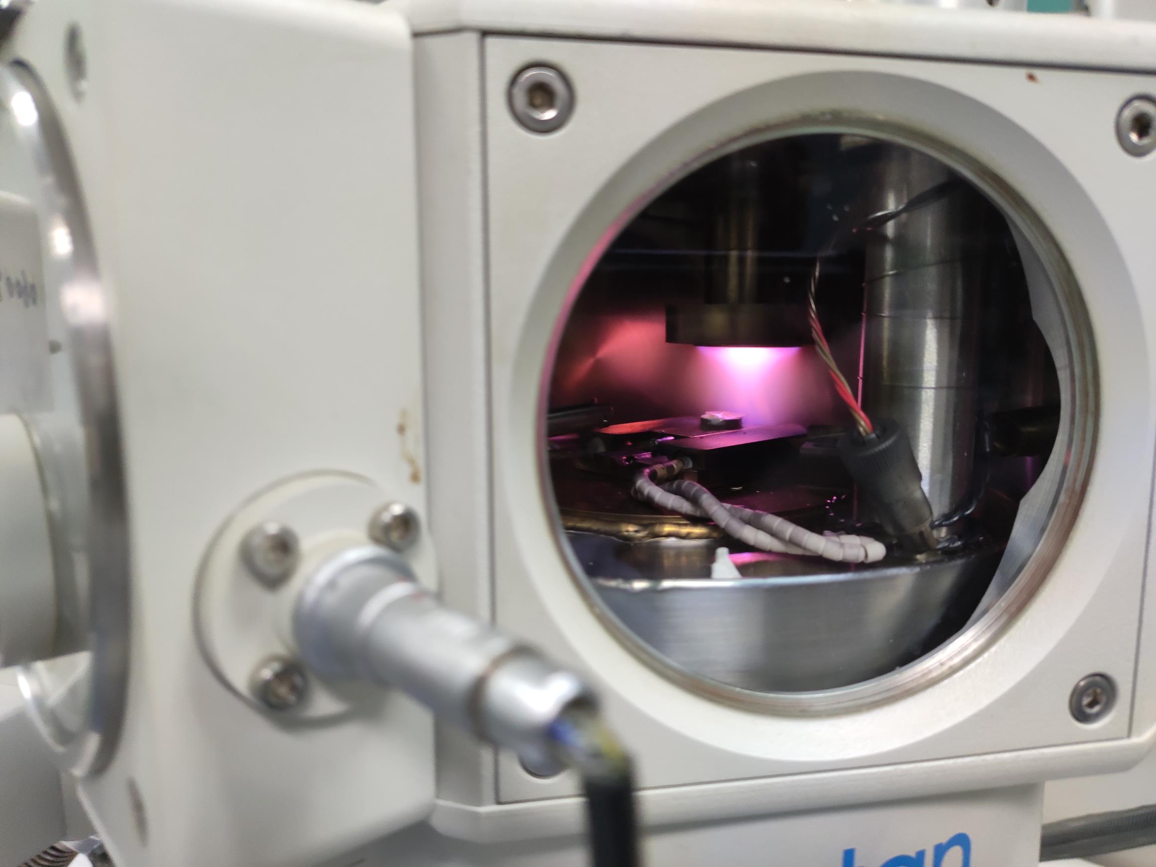
Figure 9. The rice root being sputtered. The rice root sample should be placed under the coating head during sputtering. Video 13. The sample is being sputtered
SEM Microscopy
Open the ball valve between the preparation chamber and the SEM chamber when the indicator LED light turns green (Figures 10-11).
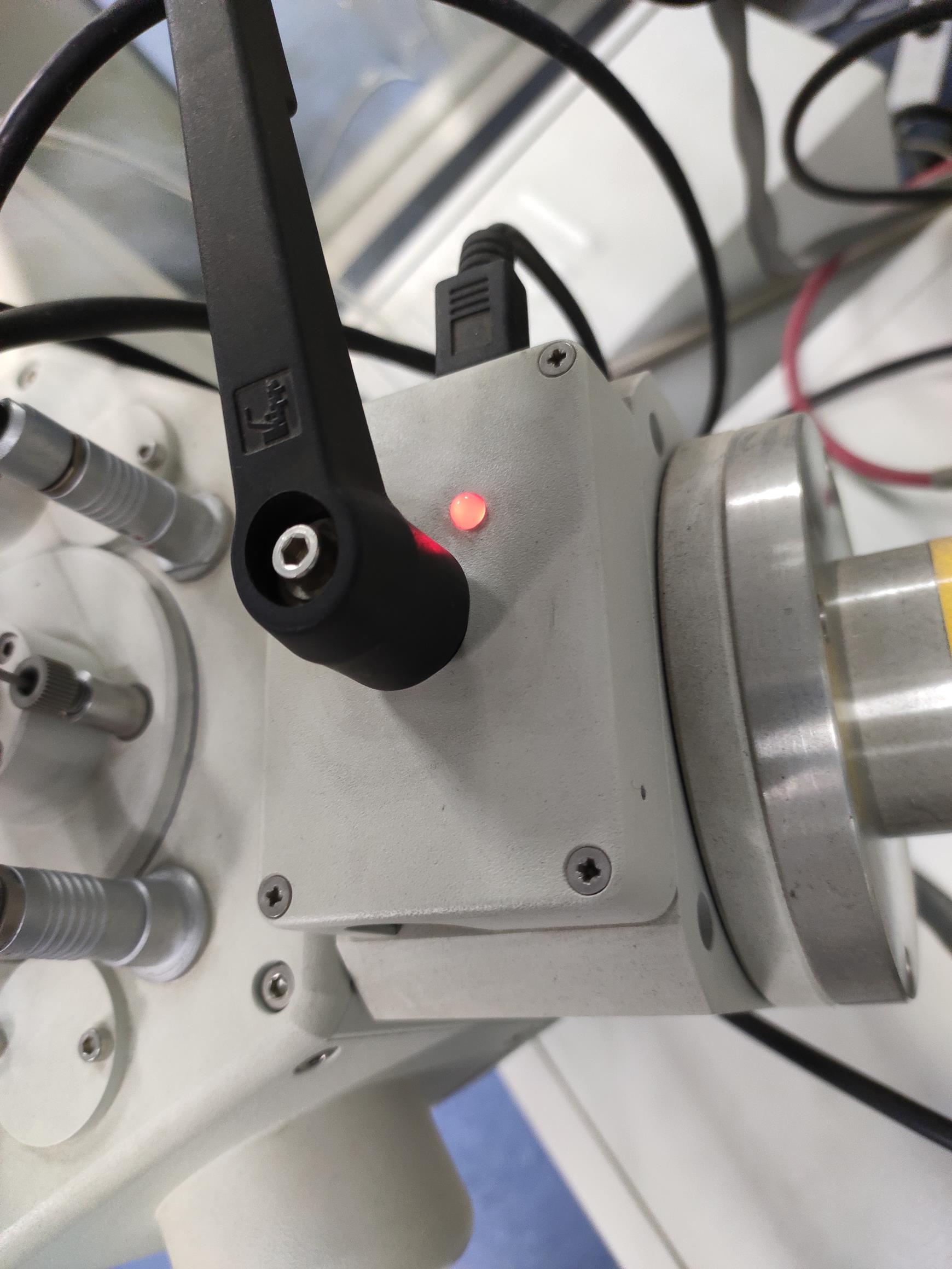
Figure 10. The ball valve LED is red. In this situation, the mechanical interlock cannot be opened.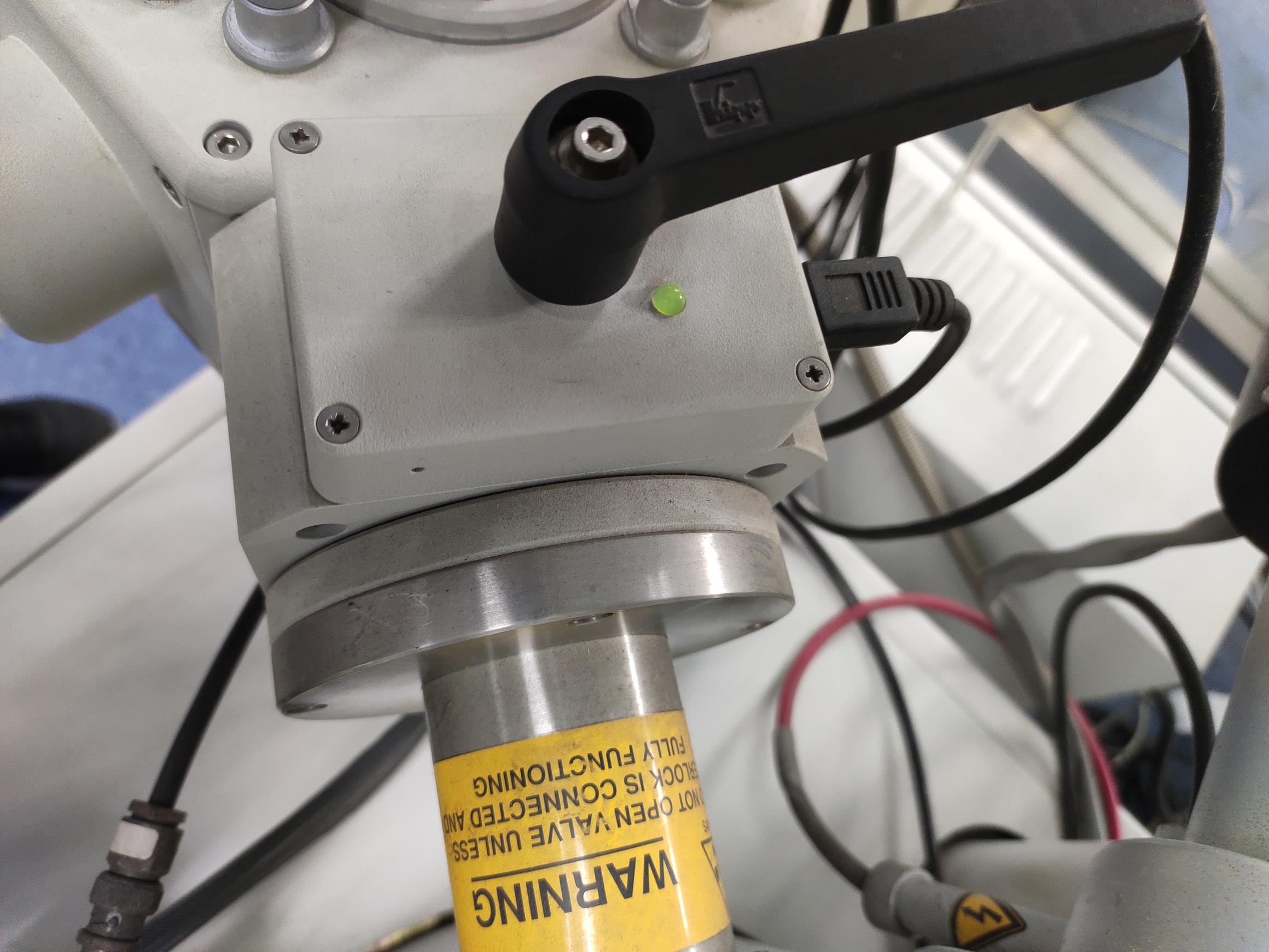
Figure 11. The ball valve LED is green. When the vacuum in the prep chamber and the SEM equilibrates, the LED turns green, and the mechanical interlock can be opened.Transfer the specimen holder to the SEM cold stage module (see Video 14).
Video 14. Transfer the sample from the prep chamber to the SEMRotate the rod and separate the specimen holder from the rod.
Retract the rod back into the prep chamber and close the ball valve. SEM imaging has now started.
Open the software and click the HV button to start the preview and shooting mode.
Set the SEM acceleration voltage (6 kV or 15 kV).
Adjust the SEM sample stage position by rotating different control knobs for the SEM standard stage (Figure 12).
Rotate the rotary functional knobs on the HITACHI control unit by adjusting MAGNIFICATION, CONTRAST, BRIGHTNESS, and FOCUS (Figure 13).
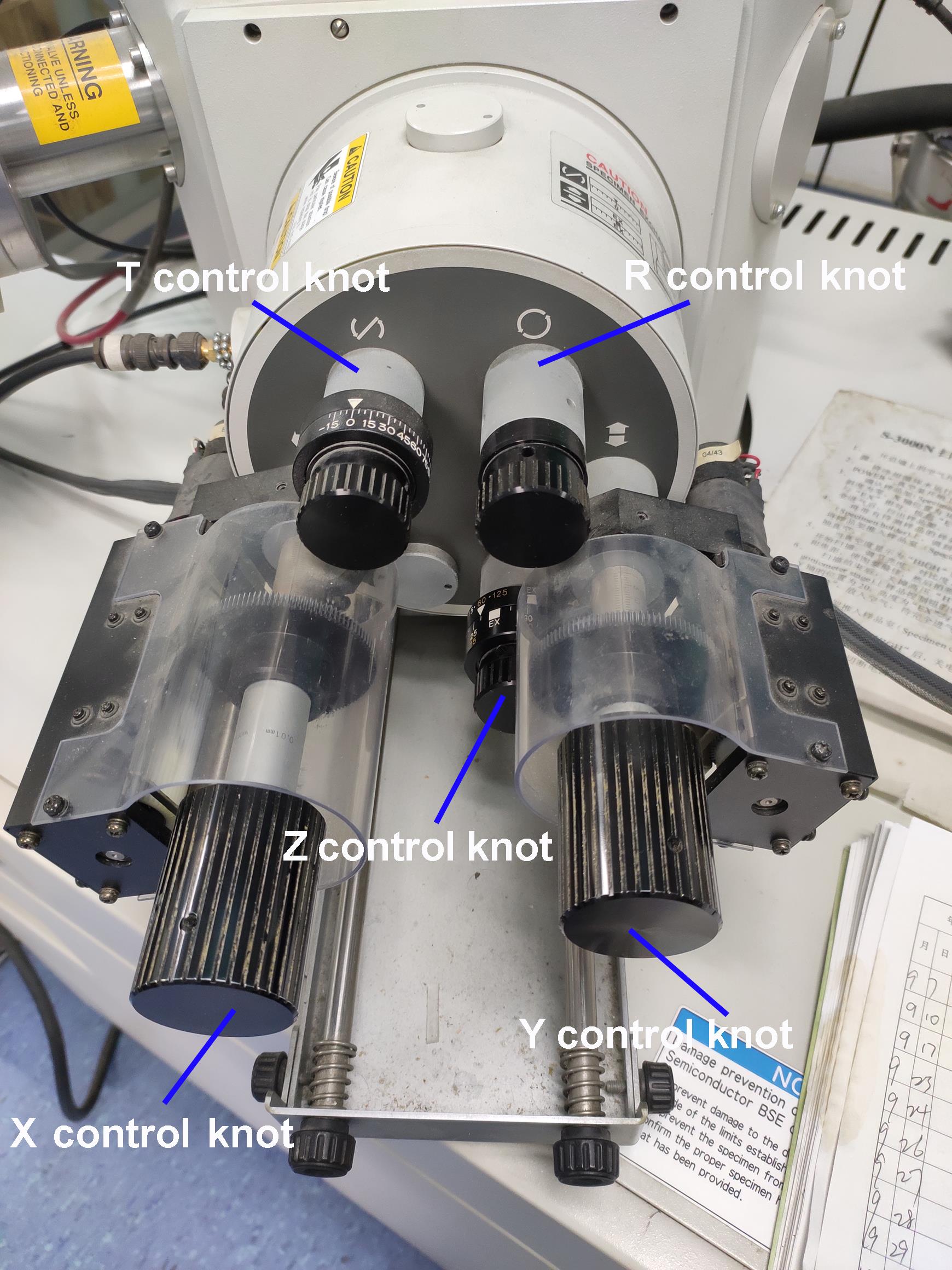
Figure 12. The standard stage of the SEM. The T control knob tilts the specimen (-20 to 90°); the R control knob rotates the specimen (±360°); the X control knob moves the specimen in the longitudinal direction; the Y control knob moves the specimen in the lateral direction; the Z control knob moves the specimen in the vertical direction.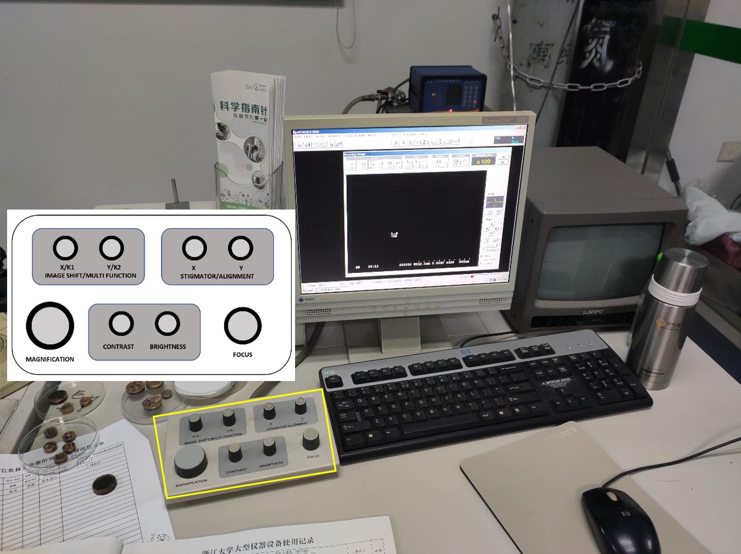
Figure 13. Appearance of the SEM display unit. The rotary knob unit is shown in the yellow rectangle. The control button layout on the unit is embedded in the image.Click the mouse to open or close dialog windows and run the settings. Input characters and comments with the keyboard.
Switch to different sample parts by moving the mouse wheel.
Click the H.R. Capture button to scan the sample. The scanning speed is optional.
Note: The slower the scanning speed, the higher the resolution of the image. However, a slow scanning speed occasionally causes image deformation.
Click the SAVE button to save and name the acquired image in the target folder.
Click the H.V. button again to turn off the SEM filament when imaging is finished.
Open the BALL VALVE, and remove the specimen holder from the Cold Stage Module located by the rod.
Haul the rod backwards and insert the holder into the dovetail stage in the prep chamber.
Close the BALL VALVE.
Haul the rod backwards to the end and shut the airlock valve.
Push the LOAD PUMP button on the Alto control panel twice and vent the airlock to remove the VTD.
Place the VTD on the slushing chamber and engage the trapdoor valve onto the control lever.
Data analysis
Root hair parameters were obtained from the cryo-SEM images (Figure 14). The root hairs from the region of 2-3 mm from the root apex were used for the statistics and analysis of the root hair parameters. According to the results, the root hair length in the Osbhlh115 mutant was much shorter than that in the wild type (Table 1). The difference in root hair diameter between the wild type and mutant was insignificant. Although the angles between root hairs and seminal roots of the wild type and mutant were not different, cryo-SEM provided an important tool for the study of the root hair angle parameter (Table 1).
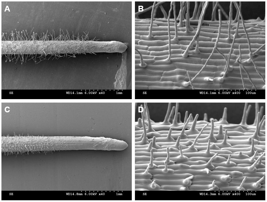
Figure 14. Root hair phenotype analyzed by cryo-SEM. A-B. Kathalath (wild type) root hair phenotype. A is 40× magnification and B is 400× magnification; C-D. Osbhlh115 mutant root hair phenotype. C is 40× magnification and D is 400× magnification.
Table 1. Quantitative parameters of the root hairs*
| Sample | Root hair length (µm) | Root hair diameter (µm) | Angle between root hair and seminal root (°) |
| Wild type | 177.92±11.00 | 6.26±0.03 | 79.67±4.42 |
| Mutant | 26.93±1.56 | 6.34±0.14 | 80.17±5.15 |
*All data were obtained according to the reference instructions (Tajima and Kato, 2013)
In addition to imaging root hairs, cryo-SEM can be used to image root cell internal structures (Figure 15). After the water in the epidermal and cortical cells is removed by sublimation, the reticulate structure and layered structure, respectively, at 2,000× magnification are shown (Figure 15B). Similar cytoplasmic lamellar and reticulate structures were found in the drupelet mesocarp cells of red raspberry (Rubus indaeus L.) (Williamson and Duncan, 1989). Conventional paraffin and resin sections could not show the true structures of the cytoplasm. When resin or paraffin replaced the water in the tissue, it likely took away some of the proteins or other components in the cytoplasm. Cryo-SEM can eliminate water through sublimation, retaining the cytoplasmic contents to the greatest extent. It was reported many years ago that electron microscope freeze-fixation was better than chemical fixation (Walther and Müller, 1999).
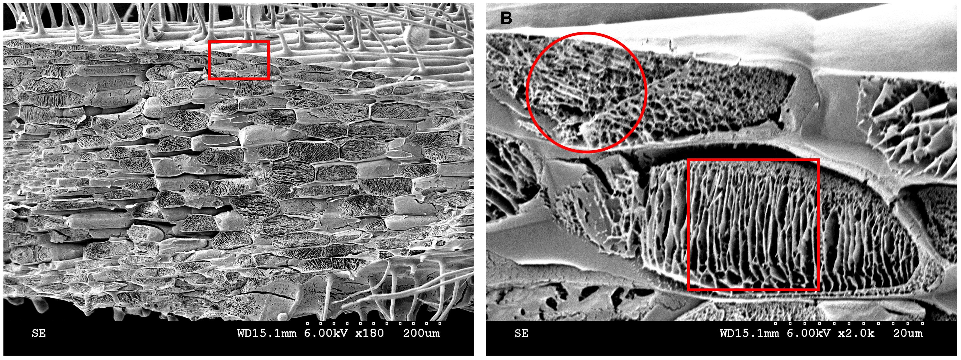
Figure 15. Cytoplasmic contents analyzed by cryo-SEM. A. Kathalath root transverse fracture cytoplasmic structure at 180× magnification. B. Enlarged view of the red rectangular zone in B at 2,000× magnification. The red circle in B indicates a reticulate structure; the red square in B indicates a lamellar structure.
Nitrogen sludge may transform into nitrogen solids during the root hair freezing process. The root hair tubular protuberant parts were broken occasionally when the specimen holder was retracted from the slush chamber. In Figure 16, a variety of broken root hair holes are visible (Figure 16A). Root hairs exhibit a large vacuole in the protruding part (Preuss et al., 2004). After the sublimation finished, the entire vacuole was evaporated to dryness and an empty cavity was left (Figure 16B). Some of the residual particles in the cavity most likely represent cytoskeletal proteins (Walther and Müller, 1999). In conclusion, there are reasons to believe that the reticulate and layered structures displayed in Figure 15B have different functions in the formation of cell morphology, organelle positioning, signal transduction, and material transportation. Note that only a small portion of the information displayed by cryo-SEM was utilized and further exploration is needed.
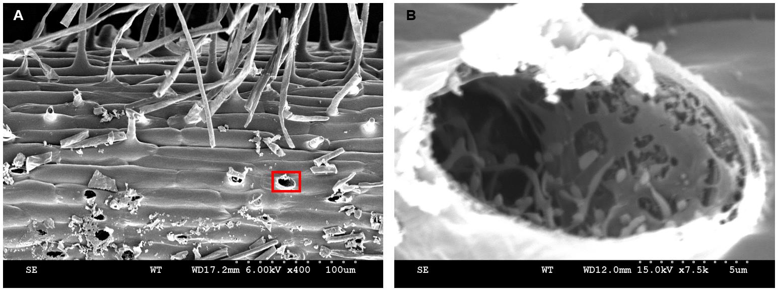
Figure 16. Broken root hairs left holes. A-B. Kathalath (wild type) root hair phenotype. A is 400× magnification and B is 7,500× magnification.
Acknowledgments
This project was supported by Zhejiang Provincial Natural Science Foundation (LY19C020002), the National Science Foundation of China NSFC (31200913), the Entrepreneurship and Innovation Project for the Overseas Returnees (or Teams) in Hangzhou (4105C5062000611), China Scholarship Council (201709645003) and National Undergraduate Innovation and Entrepreneurship Training Program (1085C5212030510). This protocol was adapted from Yu et al. (2013). We give great thanks to Mr. Hanmin Chen at Zhejiang University for his technical support. Our personal heartfelt appreciation goes to Dr. Zhiming Yu’s late advisor Professor Dr. Ping Wu at Zhejiang University. The protocol presented here was developed from a previous publication (Yu et al., 2011).
Competing interests
The authors declare no competing financial interests.
References
- Alto 2100 operator’s handbook. (2005). GATAN.
- Binder, K. (2014). Simulations clarify when supercooled water freezes into glassy structures. Proc Natl Acad Sci 111(26): 9374-9375.
- Berger, F., Linstead, P., Dolan, L. and Haseloff, J. (1998). Stomata patterning on the hypocotyl of Arabidopsis thaliana is controlled by genes involved in the control of root epidermis patterning. Dev Biol 194(2): 226-234.
- Brizzolara, S., Minnocci, A., Yembaturova, E. and Tonutti, P. (2020). Ultrastructural analysis of berry skin from four grapes varieties at harvest and in relation to postharvest dehydration. OENO One 4: 1121-1131.
- Chen, X. and Meyerowitz, E. M. (1999). HUA1 and HUA2 are two members of the floral homeotic AGAMOUS pathway. Mol Cell 3(3): 349-360.
- Cocozza, C., Minnocci, A., Tognetti, R., Iori, V., Zacchini, M. and Mugnozza, G. S. (2008). Distribution and concentration of cadmium in root tissue of Populus alba determined by scanning electron microscopy and energy-dispersive x-ray microanalysis. iForest 1(2): 96-103.
- Czarnota, M. A., Paul, R.N., Weston, L. A. and Duke, S. O. (2003). Anatomy of Sorgoleone-Secreting Root Hairs of Sorghum Species. Int J Plant Sci 164(6): 861-866.
- Ding, W., Yu, Z., Tong, Y., Huang, W., Chen, H. and Wu, P. (2009). A transcription factor with a bHLH domain regulates root hair development in rice. Cell Res 19(11): 1309-1311.
- Dolan, L., Duckett, C. M., Grierson, C., Linstead, P., Schneider, K., Lawson, E., Dean, C., Poethig, S. and Roberts, K. (1994). Clonal relationships and cell patterning in the root epidermis of Arabidopsis. Development 120: 2465-2474.
- Echlin, P. (1971). The application of scanning electron microscopy to biological research. Philo T R Soc B 261: 51-59.
- Eveling, D. W. and McCall, R. D. (1983). An evaluation of methods for preparing easily damaged cuticular surfaces of plants for scanning electron microscopy. J Microsc 129: 113-122.
- Foreman, J. and Dolan, L. (2001). Root Hairs as a Model System for Studying Plant Cell Growth. Ann Bot 88: 1-7.
- Giri, J., Bhosale, R., Huang, G., Pandey, B.K., Parker, H., Zappala, S., Yang, J., Dievart, A., Bureau, C., Ljung, K., Price, A., Rose, T., Larrieu, A., Mairhofer, S., Sturrock, C.J., White, P., Dupuy, L., Hawkesford, M., Perin, C., Liang, W., Peret, B., Hodgman, C. T., Lynch, J., Wissuwa, M., Zhang, D., Pridmore, T., Mooney, S.J., Guiderdoni, E., Swarup, R. and Bennett, M.J. (2018). Rice auxin influx carrier OsAUX1 facilitates root hair elongation in response to low external phosphate. Nat Commun 9(1): 1408.
- Huang, J., Kim, C.M., Xuan, Y.H., Liu, J., Kim, T.H., Kim, B.K. and Han, C.D. (2013). Formin homology 1 (OsFH1) regulates root-hair elongation in rice (Oryza sativa). Planta 237(5): 1227-1239.
- Ishida, T., Kurata, T., Okada, K. and Wada, T. (2008). A genetic regulatory network in the development of trichomes and root hairs. Annu Rev Plant Biol 59: 365-386.
- Kaneko, Y., Matsushima, H., Wada, M. and Yamada, M. (1985). A study of living plant specimens by low-temperature scanning electron microscopy. J Electron Microsc Tech 2: 1-6.
- Kim, C. M. and Dolan, L. (2016). ROOT HAIR DEFECTIVE SIX-LIKE Class I Genes Promote Root Hair Development in the Grass Brachypodium distachyon. PLoS Genet 12(8): e1006211.
- Larkin, J. C., Brown, M. L. and Schiefelbein, J. (2003) How do cells know what they want to be when they grow up? Lessons from epidermal patterning in Arabidopsis. Annu Rev Plant Biol 54: 403-430.
- Lefebvre, D. D. (1985). Stomata on the Primary Root of Pisum sativum L. Ann Bot 55(3): 337-341.
- Limmer, D. T. and Chandler, D. (2014). Theory of amorphous ices. Proc Natl Acad Sci 11(26): 9413-9418.
- McMullan, D. (1995). Scanning Electron Microscopy 1928–1965. Scanning 17: 175-185.
- Mendrinna, A. and Persson, S. (2015). Root hair growth: it's a one way street. F1000Prime Rep 7: 23.
- Müller, M. and Schmidt, W. (2004). Environmentally induced plasticity of root hair development in Arabidopsis. Plant Physiol 134(1): 409-419.
- Preuss, M. L., Serna, J., Falbel, T. G., Bednarek, S. Y. and Nielsen, E. (2004). The Arabidopsis Rab GTPase RabA4b localizes to the tips of growing root hair cells. Plant Cell 16(6): 1589-1603.
- Read, N. D. and Jeffree, C. E. (1991). Low-temperature scanning electron microscopy in biology. J Microsc 161: 59-72.
- Refshauge, S., Watt, M., McCully, M. and Huang, C. (2006). Frozen in time: a new method using cryo-scanning electron microscopy to visualize root-fungal interactions. New Phytol 172(2): 369-374
- Rey, L. R. (1960). Thermal analysis of eutectics in freezing solutions. Ann NY Acad Sci pp.510-534.
- Ryan, E., Grierson, C. S., Cavell, A., Steer, M. and Dolan, L. (1998). TIP1 is required for both tip growth and non-tip growth in Arabidopsis. New Phytol 138: 49-58.
- Sargent, J. A. (1983). The preparation of leaf surfaces for scanning electron microscopy: a comparative study. J Microsc 129: 103-110.
- Sargent, J. A. (1986). Cryo-preservation of roots for scanning electron microscopy. Ann bot 58: 183-185.
- Tajima, R. and Kato, Y. (2013). A Quick Method to Estimate Root Length in Each Diameter Class Using Freeware ImageJ. Plant Prod Sci 16: 9-11.
- Utsumi, Y., Sano, Y., Fujikawa, S., Funada, R. and Ohtani, J. (1998). Visualization of Cavitated Vessels in Winter and Refilled Vessels in Spring in Diffuse-Porous Trees by Cryo-Scanning Electron Microscopy. Plant Physiol 117: 1463-1471.
- Vartanian, N., Wertheimer, D. S. and Couderc, H. (1983). Scanning electron microscopic aspects of short tuberized roots, with special reference to cell rhizodermis evolution under drought and rehydration. Plant Cell Environ 6: 39-46.
- Vega-Gálvez, A., Lemus-Mondaca, R., Bilbao-Sáinz, C., Fito, P. and Andrésc, A. (2008). Effect of air drying temperature on the quality of rehydrated dried red bell pepper (var. Lamuyo). J Food Eng 85(1): 42-50.
- Walther, P. and Muller, M. (1999). Biological ultrastructure as revealed by high resolution cryo-SEM of block faces after cryo-sectioning. J Microsc 196: 279-287.
- Wang, C. X., Qi, C. Y., Luo, J. H., Liu, L., He, Y. and Chen, L. Q. (2019). Characterization of LRL5 as a key regulator of root hair growth in maize.Plant J 98(1): 71-82.
- Webb, J. and Jackson, M. B. (1986). A Transmission and Cryo-Scanning Electron Microscopy Study of the Formation of Aerenchyma (Cortical Gas-Filled Space) in Adventitious Roots of Rice (Oryza sativa). J Exp Bot 37(6): 832-841.
- Williamson, B. and Duncan, G. H. (1989). Use of cryo-techniques with scanning electron microscopy to study infection of mature red raspberry fruits by Botrytis cinerea. New Phytol 111(1): 81-88.
- Yan, Y. (2010). Tribology and tribo-corrosion testing and analysis of metallic biomaterials. Met Biomed Devic Ch.7: 178-201.
- Yi, K., Menand, B., Bell, E. and Dolan, L. (2010). A basic helix-loop-helix transcription factor controls cell growth and size in root hairs. Nat Genet 42(3): 264-267.
- Yu, L., Shi, D., Li, J., Kong, Y., Yu, Y., Chai, G., Hu, R., Wang, J., Hahn, M. G. and Zhou, G. (2014). CELLULOSE SYNTHASE-LIKE A2, a glucomannan synthase, is involved in maintaining adherent mucilage structure in Arabidopsis seed. Plant Physiol 164(4): 1842-1856.
- Yu, Z., Chen, H., Tong, Y. and Wu, P. (2013). Analysis of rice root hair morphology using cryo-scanning electron microscopy. Methods Mol Biol 956: 243-248.
- Yu, Z., Kang, B., He, X., Lv, S., Bai, Y., Ding, W., Chen, M., Hyung-Taeg, C. and Wu, P. (2011). Root hair-specific expansins modulate root hair elongation in rice. Plant J 66(5): 725-734.
- Zenone, A., Alagna, A., D'Anna, G., Kovalev, A., Kreitschitz, A., Badalamenti, F. and Gorb, S. N. (2020). Biological adhesion in seagrasses: The role of substrate roughness in Posidonia oceanica (L.) Delile seedling anchorage via adhesive root hairs. Mar Environ Res 160: 105012.
- Zou, H. Y., Wenwen Y. H., Zang G. C., Kang Z. H., Zhang Z. Y., Huang J. L. and Wang G. X. (2015). OsEXPB2, a β-expansin gene, is involved in rice root system architecture. Mol Breeding 35: 41.
Article Information
Copyright
© 2021 The Authors; exclusive licensee Bio-protocol LLC.
How to cite
Yan, H., Wang, Y., Zhang, J., Cui, X., Wu, J., Zhou, J., Chen, Y., Lu, J., Guo, R., Ou, M., Lai, H. and Yu, Z. (2021). Rice Root Hair Phenotypes Imaged by Cryo-SEM. Bio-protocol 11(11): e4037. DOI: 10.21769/BioProtoc.4037.
Category
Plant Science > Plant developmental biology > Morphogenesis
Developmental Biology > Morphogenesis > Organogenesis
Cell Biology > Cell structure > Cell wall
Do you have any questions about this protocol?
Post your question to gather feedback from the community. We will also invite the authors of this article to respond.