


- Protocols

- Articles and Issues
- For Authors
- About
- Become a Reviewer


Hemispherectomy-Based Optical Window for In Vivo Visualization of Trigeminal Ganglion Neurons in Mice

Published: Vol 16, Iss 13, Jul 5, 2026 DOI: 10.21769/BioProtoc.5716 Views: 329
Reviewed by: Olga KopachRaniki KumariAnonymous reviewer(s)
 PDF
PDF  Ask a question
Original research article
The authors used this protocol in:

Jul 2025
Advertisement


Protocol Collections
Comprehensive collections of detailed, peer-reviewed protocols focusing on specific topics




Related protocols
Abstract
Functional imaging of neural structures at the base of the cranium, including the trigeminal ganglion (TG), is technically challenging due to limited optical access. The TG—the largest sensory ganglion in the head—houses primary afferent neurons that relay information from the teeth, oral cavity, and face, yet investigation of somatosensory processing at the population level has remained limited. Here, we present a surgical procedure for an optical-window preparation that enables direct optical access to the TG. The ganglion is exposed by a large temporal craniotomy with removal of overlying tissue, and a glass cuboid is then placed in direct contact with the TG to suppress motion while maintaining the cranial cavity as a closed compartment without continuous perfusion. This preparation allows reliable visualization and recording of individual TG neurons during controlled stimulation of diverse facial and intraoral sites. Our approach provides a practical platform to map peripheral sensory representations within the TG and to investigate mechanisms underlying dental sensation, orofacial pain, and trigeminal circuit function.
Key features
• Establishes stable optical access to the mouse trigeminal ganglion using a hemispherectomy-based glass cuboid cranial window preparation.
• Reduces motion artifacts through direct cuboid-TG contact, enabling robust single-neuron calcium imaging.
• Provides a large field of view of the whole TG with fluorescence microscopy hardware and supports imaging in vivo.
Keywords: Trigeminal ganglion In vivo calcium imaging
Epifluorescence microscopy
Cranial window
Hemispherectomy
In vivo calcium imaging
Epifluorescence microscopy
Cranial window
Hemispherectomy
Graphical overview

Schematic overview of the trigeminal ganglion (TG) window implantation. The head plate is horizontally fixed to the skull, followed by placement of a glass cuboid onto the exposed TG after hemispherectomy. This enables stable optical access and visualization of the TG through the glass window. V1–V3 denote the three branches of the trigeminal nerve: V1, ophthalmic; V2, maxillary; and V3, mandibular. A, anterior; P, posterior; M, medial; L, lateral.
Background
The trigeminal system provides the principal gateway by which mechanical, thermal, and nociceptive signals from the face and oral cavity reach the brain [1–5]. These inputs shape everyday behaviors—feeding, speech-related movements, grooming—and are also central to common clinical conditions such as dental hypersensitivity, temporomandibular disorders, migraine, and trigeminal neuralgia. Trigeminal ganglion (TG) neurons are the first-order sensory afferents for these modalities, projecting to brainstem nuclei and higher-order somatosensory regions where structured representations of the periphery emerge [2,6–15]. Analogous to the dorsal root ganglia, which convey somatosensory information from the body, the TG contains, together with satellite glial cells, pseudounipolar sensory neurons of diverse sizes and functions. TG neurons are highly heterogeneous, with relatively fewer proprioceptive neurons and a larger proportion of cold-sensitive neurons, in addition to tactile-responsive neurons [16–18]. Despite extensive work on downstream somatosensory processing in the brainstem and cortex, how ensembles of TG neurons collectively encode distinct orofacial structures and stimulus features in vivo remains poorly resolved.
A key limitation has been methodological: the TG is deep and mechanically coupled to surrounding tissues, making it difficult to achieve optical access with sufficient stability for single-neuron imaging. Traditional extracellular recordings [19,20] and anatomical tracing [21] have provided important insights, but they sample limited numbers of neurons at a time and do not readily capture the coordinated population dynamics that may underlie sensory coding and plasticity. To address this knowledge gap, we developed a surgical preparation for in vivo calcium imaging [22–29] that combines direct exposure of the TG [30–33] via hemispherectomy with placement of a rigid glass cuboid window that mechanically stabilizes the ganglion. This protocol enables wide-field monitoring of large TG neuronal populations in genetically encoded calcium indicator mice (Figure 1) [5] and can be combined with optogenetic and chemogenetic manipulation, facilitating functional mapping of facial and intraoral representations and offering a versatile entry point for studying trigeminal sensory processing and disease-relevant mechanisms [5].
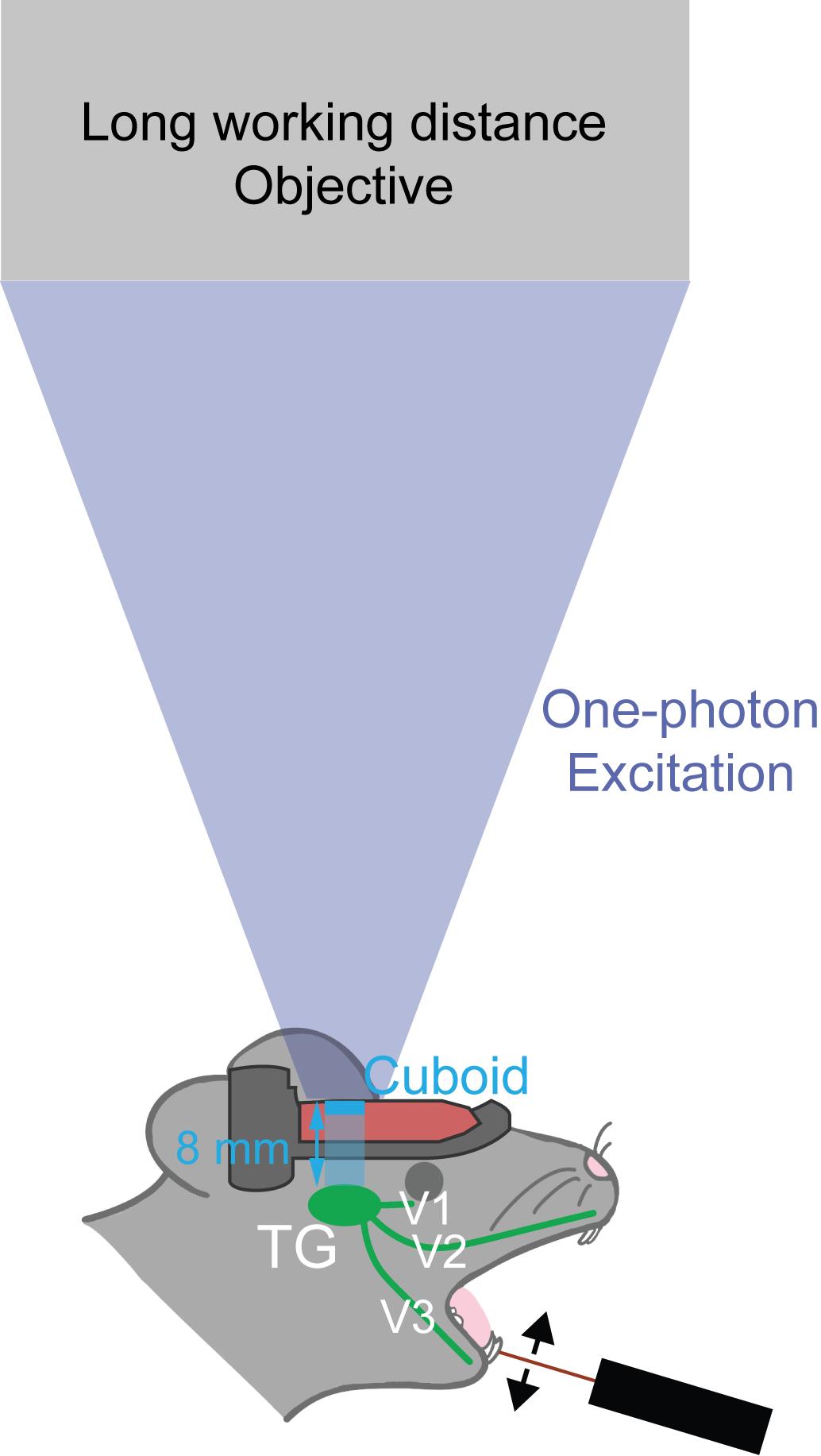
Figure 1. Schematic illustration of trigeminal ganglion (TG) innervation of the face, including the oral cavity.The glass cuboid enables in vivo calcium imaging of the entire TG. In our previous work [5], sensory stimulation was applied to the left mandibular incisor using a piezoelectric bender. V1–V3 denote the three branches of the trigeminal nerve: V1, ophthalmic; V2, maxillary; and V3, mandibular. Working distance of the objective lens needs to be longer than 8 mm (100 mm for MV PLAPO 1×).
Materials and reagents
Biological materials
1. Thy1-GCaMP6f mice (aged >8 weeks) (The Jackson Laboratory, stock number: 025393)
Reagents
1. Carprofen (Rimadyl, catalog number: VetRx MW 026357)
2. Lidocaine hydrochloride jelly, 2% (IMS, catalog number: 76329-3015-5)
3. Cyanoacrylate adhesive (Aron Alpha, TOAGOSEI, catalog number: 04613)
4. Dental cement (Jet Denture Repair Package, LANG, catalog number: 1223CLR)
5. Phosphate-buffered saline (PBS), 10× (Gibco, catalog number: 70011-044)
6. Hair remover cream (Veet, catalog number: 3299655)
7. Antibiotic ointment (Medi-First, catalog number: 22373)
8. Povidone-iodine, 10% (Betadine, catalog number: 67618-150-01)
9. Isoflurane (Piramal Critical Care, catalog number: 66794-017-25)
10. Ketamine 100 mg/mL (Patterson Veterinary, catalog number: 07-894-8462)
11. Xylazine 100 mg/mL (AKORN animal health, catalog number: 59399-111-50)
12. Bupivacaine 5 mg/mL (Cook-Waite, catalog number: 99184)
Laboratory supplies
1. Glass cuboid, 3 × 3 × 8 mm (UQG Optics; glass cuboid, 3 mm × 3 mm × 8 mm)
2. Head post/head plate (316L stainless steel, Craftcloud)
3. Forceps (FST, catalog number: 11252-00)
4. Micro-scissors (FST, catalog number: 15000-04)
5. Scissors (FST, catalog number: 14060-09)
6. Surgifoam (Ethicon, catalog number: 1972)
7. Needles: 20G (BD, catalog number: 305176), 18G (Air-Tite, catalog number: 14-817-220), 16G (Air-Tite, catalog number: 14-817-104)
8. Cotton swabs (Puritan, catalog number: 826-WC)
9. Kimwipes (Kimberly-Clark Professional, catalog number: 34155)
10. 3 mL transfer pipettes (Falcon, catalog number: 357575)
11. Tissue culture dish (Fisherbrand, catalog number: FB012920)
12. Insulin syringe with fixed needle (Sol-Vet, catalog number: V12905)
13. Sandpaper, 80 grit
14. Toothpicks
15. Erlenmeyer flask, 500 mL (KIMAX, catalog number: 26500)
16. Hose couplers (ROTH, catalog number: E806.1-E809.1)
17. PFA tubing (ROTH, catalog number: 1NAY.1-1NAT.1)
18. Two-hole rubber stopper (Fisherbrand, catalog number: 14-140S)
19. Sandpaper (Johnson abrasives, catalog number: 10110-15)
20. Toothpicks (KingSeal, catalog number: 77150)
Equipment
1. Anesthetic vaporizer (E-Z Systems, model: EZ-108SA)
2. Oxygen concentrator (VARON, model: Y-105)
3. Stereotaxic alignment system (KOPF, model: 1900)
4. Auxiliary ear bars (Narishige, model: EB-5N)
5. Animal temperature controller (WPI, model: ATC 1000)
6. Micro drill (Harvard Apparatus, model: 75-1874)
7. LED illumination (Amscope, model: LED-50WY)
8. Germinator (Braintree Scientific, model: NC9956482)
9. Vacuum regulator (Ohio Medical, model: PISA)
10. Epifluorescence microscope (Olympus, model: MVX-10)
11. Blue LED (Thorlabs, model: SOLIS-470)
12. 1× objective lens (MV PLAPO 1×/0.25 NA)
13. Filter cube (U-MF/XL, Olympus), containing an excitation bandpass filter of 470 nm, a dichroic filter of 495 nm, and an emission bandpass filter of 525/50 nm
14. Monochrome CMOS camera (Thorlabs, model: CS135MU)
15. Piezoelectric bender (Thorlabs, model: PB4NB2S)
16. Wixey digital angle gauge (Wixey, model: WR300 Type 2)
Software and datasets
1. Tinkercad (Autodesk, https://www.tinkercad.com/)
Procedure
A. Preparation of the head plate and glass cuboid
1. Design a custom head plate (using Tinkercad) and order (via Craftcloud) the plate fabricated from 316L stainless steel, which allows rigid head fixation during imaging (Figure 2A–B).
2. Prepare a glass cuboid (3 mm × 3 mm × 8 mm; height × width × depth, ordered from UQG optics) to serve as the optical element of the TG window (Figure 2C–D).
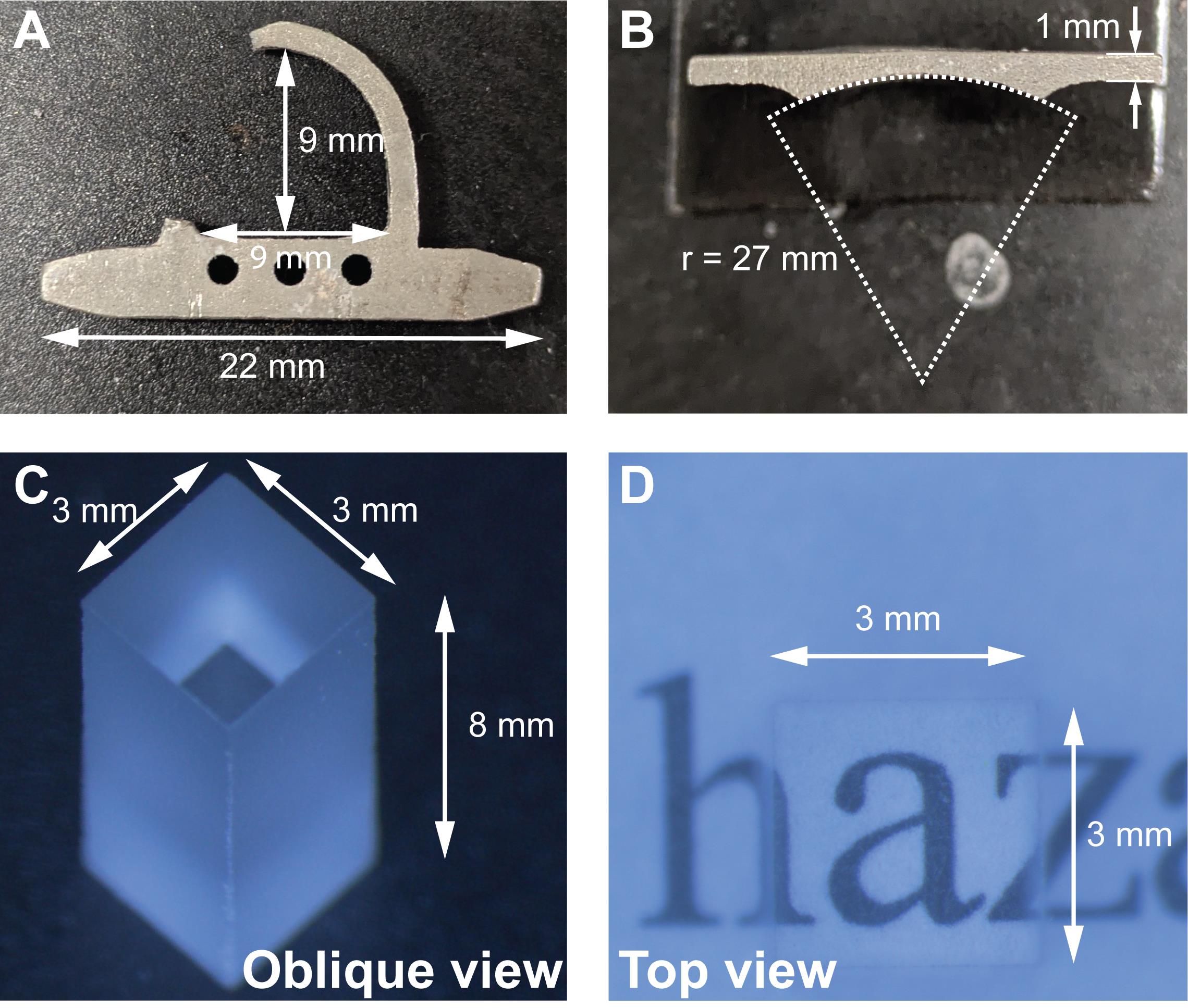
Figure 2. Custom-designed head plate and glass cuboid for trigeminal ganglion (TG) imaging. (A, B) Top and rear views of the head plate. (C, D) Oblique and top views of the 3 × 3 × 8 mm glass cuboid.
B. Preparation of the suction system
1. Blunt 16-, 18-, and 20-gauge needles by cutting off the tips and smoothing the cut ends with sandpaper.
2. Connect a laboratory vacuum valve to a 500 mL Erlenmeyer flask dust trap via a vacuum regulator. Attach the tubing to the dust trap and fit the distal end with a blunted needle to serve as the suction tip (Figure 3).
Note: The suction system is an efficient approach to remove brain tissue while simultaneously controlling bleeding, thereby facilitating exposure of the TG and maintaining a clear surgical field. The smaller gauge needles need to be used to perform slow but subtle suction.
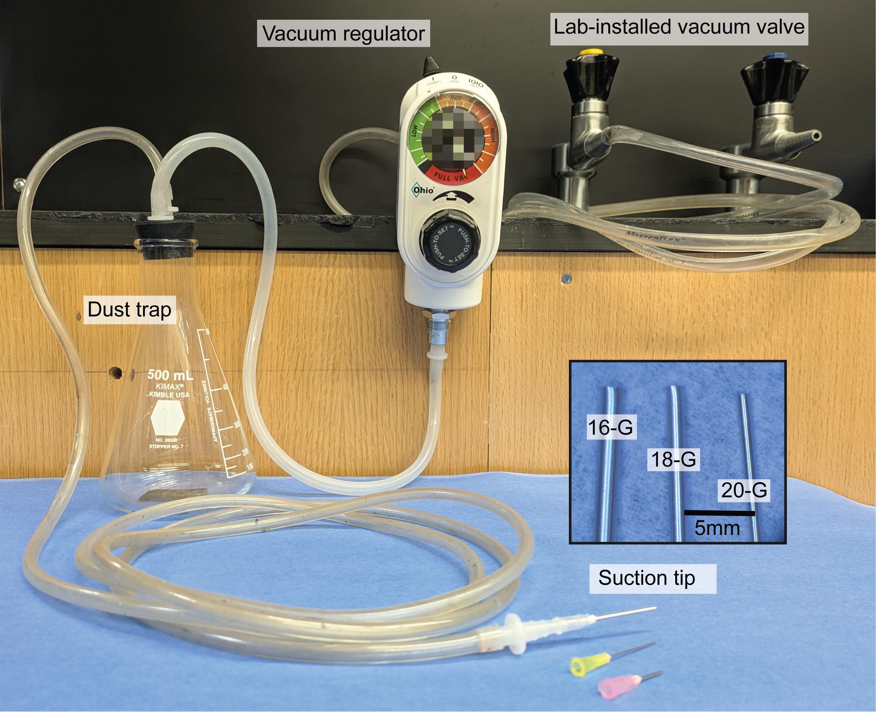
Figure 3. Example suction system used for tissue aspiration during hemispherectomy. The suction tip consists of a flattened needle, whose size can be easily adjusted depending on the surgical requirement, e.g., structures to be sucked. Suction power is controlled using a vacuum regulator.
C. Trigeminal ganglion window implantation
Note: Disinfect surgical instruments, the head plate, and cotton swabs with 70% ethanol and sterilize prior to use (e.g., autoclave, germinator, 30 s).
1. Pre-emptive analgesia: Administer carprofen (5 mg/kg, subcutaneous) 30 min prior to surgery to provide pre-emptive analgesia and reduce intraoperative and postoperative nociceptive responses.
2. Anesthesia and preparation
a. Induce anesthesia with isoflurane (4% in oxygen).
b. Place the mouse (>8 weeks old) in a stereotaxic frame with ear bars and maintain anesthesia at 1.5% isoflurane.
c. Apply ophthalmic antibiotic ointment to both eyes to prevent corneal drying.
d. Remove scalp hair using hair remover cream.
e. Disinfect the scalp with 10% povidone-iodine. Apply 2% lidocaine or 0.25% bupivacaine subcutaneously at the incision site for local analgesia and allow it to take effect for ~3 min.
3. Expose the skull and attach head plate
a. Make a midline scalp incision to expose the dorsal skull surface (Figure 4A).
b. Tilt the head ~20° to the right (optional; used here for convenience).
c. Remove the left temporal muscle using micro-scissors and forceps (Figure 4B–C).
d. Return the head to a horizontal position.
e. Remove the periosteum from the skull surface using cotton swabs and a microdrill.
f. Position the head plate horizontally with sufficient clearance above the left temporal bone. Then, fix it to the skull with cyanoacrylate adhesive (Figure 4D) and allow it to cure (~5 min).
g. Reinforce fixation with dental cement applied at the plate edges (Figure 4E) and allow it to set (~10 min).
4. Temporal bone craniotomy
a. Tilt the head again ~20° to the right (optional; used here for convenience).
b. Using a microdrill, create a groove outlining a large craniotomy extending from the left temporal bone to ~2 mm left of the midline; include the left dorsal temporal bone, most of the left parietal bone, and the caudal half of the frontal bone (Figure 4F).
Note: During skull drilling, use an air blower to remove bone debris and prevent overheating.
c. Gradually deepen the groove until the bone flap can be depressed with light pressure.
d. Soak the groove with 1× PBS and wait ~5 min to soften remaining attachments.
e. Insert forceps or micro-scissors between the skull and brain surface to sever remaining connections, then gently lift off the bone flap (Figure 4G).
f. Control bleeding using cotton swabs and Surgifoam placed along the bone edges as needed.
5. Hemispherectomy and TG exposure
a. Reduce isoflurane to ~1% for hemispherectomy.
Notes:
1. Continuous 1.5% isoflurane may result in excessively deep anesthesia during hemispherectomy, which can increase the risk of intraoperative death in mice.
2. During and after hemispherectomy, periodically assess anesthetic depth (e.g., tail pinch).
b. Continuously irrigate the exposed cortex with 1× PBS.
c. Gradually aspirate cortical and subcortical tissue within the craniotomy using the suction system (Figure 4H).
d. As bleeding occurs, repeatedly irrigate the aspiration site with 1× PBS using a transfer pipette and remove pooled blood/fluid by suction.
e. Continue aspiration/irrigation cycles until the left TG becomes visible (Figure 4I).
Note: Gentle suction is initiated from the more lateral region and gradually advanced toward the medial side, which facilitates the detachment of residual brain tissue from the brain cavity, thereby improving visualization of the underlying TG.
f. Adjust head position to ~5° rightward rotation and ~10° dorsal tilt to optimize access.
g. If necessary, switch to a 20G suction tip and remove the remaining tissue without touching the TG surface.
h. Repeat irrigation/suction cycles until the TG is fully exposed and bleeding is controlled (Figure 4J).
6. Glass cuboid placement and sealing
a. Using forceps, gently place the glass cuboid directly onto the exposed TG. Apply minimal pressure to prevent blood from entering the cuboid–TG interface (Figure 4K).
b. Pre-soak Surgifoam pieces (~2 mm) in 1× PBS for ~10 min.
c. Pack PBS-soaked Surgifoam into the space between the cuboid and surrounding tissue to stabilize the cuboid and absorb residual blood (Figure 4L–M).
Note: To prevent the adhesive from entering the cranial cavity, pack Surgifoam until it slightly protrudes above the skull margin. Because PBS-soaked Surgifoam can shrink, a greater volume can be packed than appears visually.
d. Apply cyanoacrylate adhesive to the head plate to secure the cuboid; maintain gentle downward pressure until cured (~5 min) (Figure 4N).
e. Reinforce fixation with dental cement applied over the hardened adhesive and allow it to set (~10 min) (Figure 4O–P).
Note: This is a non-survival procedure. The surgery typically takes 90 min, followed by approximately 1 h for imaging.
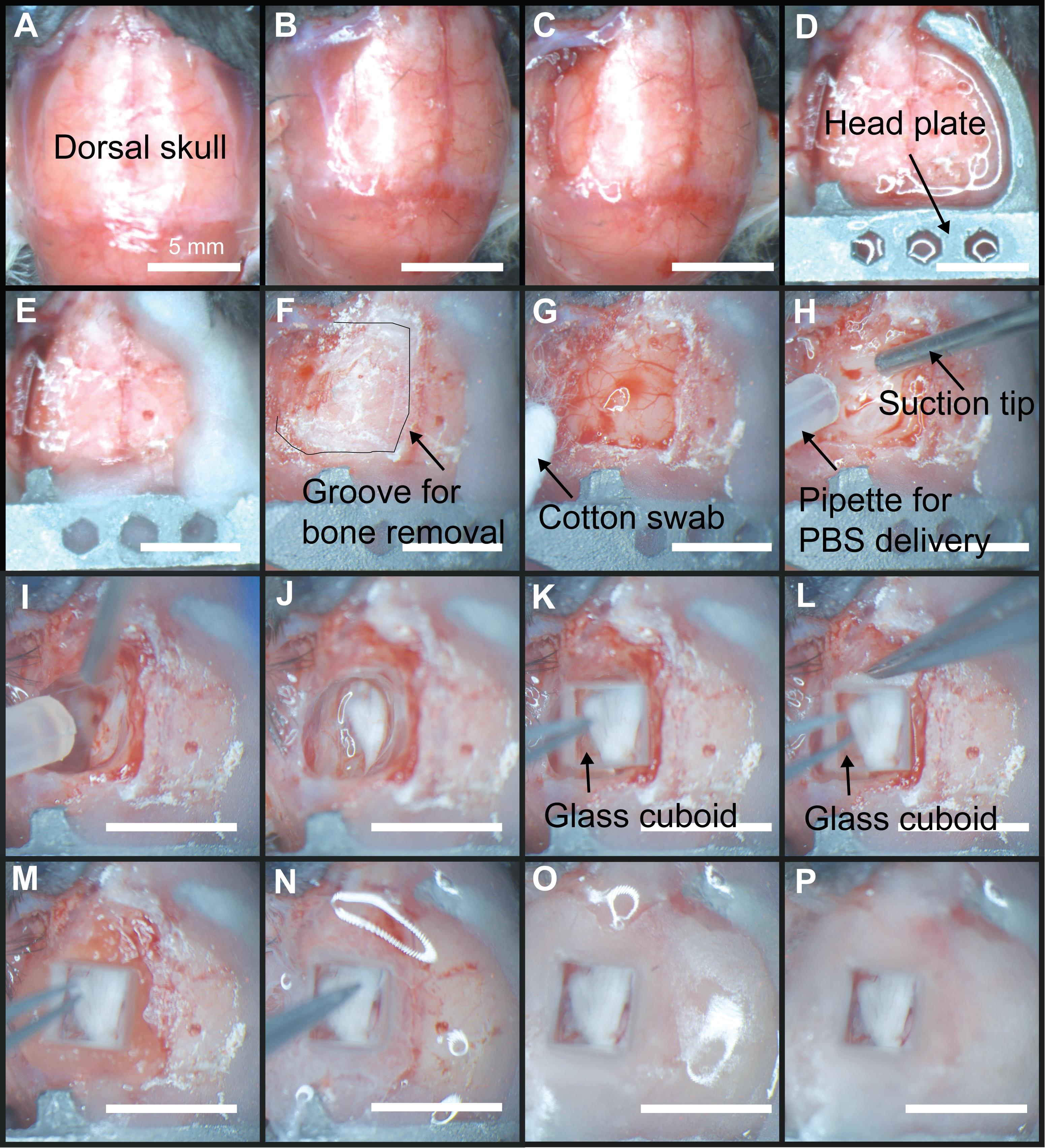
Figure 4. Step-by-step procedure for trigeminal ganglion (TG) window implantation. (A) Midline scalp incision to expose the dorsal skull surface. (B–C) Removal of the left temporal muscle. (D) Positioning and attachment of the head plate horizontally onto the skull using cyanoacrylate adhesive. (E) Reinforcement of head plate fixation with dental cement. (F) Creation of a groove for craniotomy. (G) Removal of the bone flap. (H) Gradual aspiration of cortical and subcortical tissue. The cannula on the right is a 20G needle. The tube on the left is to apply phosphate buffer saline (PBS) to wash out bleeding. (I) Initial visualization of the left TG following tissue removal. The needle is a 20G needle. (J) Full exposure of the TG after repeated aspiration and irrigation cycles with bleeding control. (K) Placement of a glass cuboid directly onto the exposed TG with minimal pressure using fine forceps. (L–M) Packing of PBS-soaked Surgifoam (gelatin sponge) around the cuboid. (N) Securing the glass cuboid to the head plate using cyanoacrylate adhesive. (O–P) Reinforcement of the implant with dental cement to ensure stable fixation for imaging. Scale bars, 5 mm.
Validation of protocol
We validated this procedure using in vivo calcium imaging, which was performed as described in the methods section of our previously published study [5]. Briefly, once the glass cuboid was secured, the animal was anesthetized with an intraperitoneal injection of a ketamine/xylazine cocktail (0.2 mL) and placed under an epifluorescence microscope (MVX, Olympus) for one-photon imaging. We chose this microscope because of its long working distance, which accommodates the 8 mm cuboid.
Sensory stimulation was applied to the facial labial surface of the left mandibular incisor and the outer surface of the lower lip in the diastema region using a toothpick attached to a piezoelectric bender. Each trial consisted of 15 stimuli delivered over 3 s at 200 ms intervals, with a 3 s baseline period before and after stimulation. The stimulation force ranged from 20 to 40 mN. This procedure was repeated for 10 trials per stimulation site.
During stimulation, excitation light was provided by a blue LED, and emitted fluorescence was detected using a monochromatic camera (Thorlabs). Images were acquired at a sampling rate of 20–30 frames per second with a resolution of 512 × 512 pixels.
The imaging data were analyzed using a custom-written MATLAB program, as previously described [25–27,34]. Imaging data were processed for motion correction and registration. Cells were detected for region-of-interest (ROI) drawing using a custom-made MATLAB program [25,35]. Fluorescence traces were calculated as the sum of pixel values for each ROI and normalized to baseline fluorescence, defined as the 1-s period prior to stimulus onset, to calculate ΔF/F0.
Using this preparation, stimulus-evoked calcium responses can be reliably recorded from TG neurons through the glass cuboid window. In the original study, tactile stimulation of the lower incisor or lower lip elicited reproducible activity in subsets of TG neurons during imaging under anesthesia (Figure 5). We adopted one-photon imaging because the cuboid requires an objective lens with a long-working distance (>8 mm).
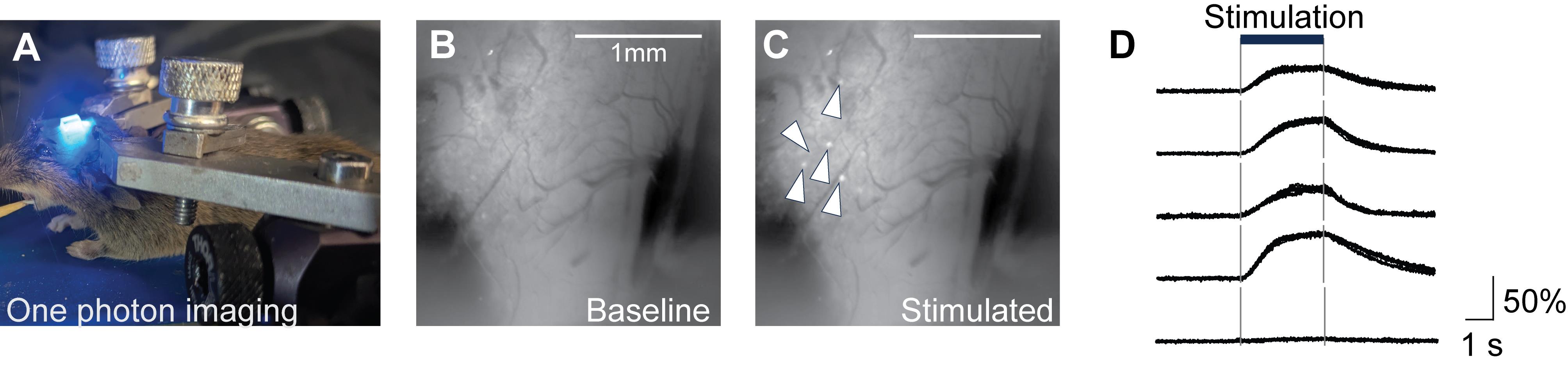
Figure 5. Example in vivo calcium imaging of the trigeminal ganglion (TG) through the glass cuboid window. (A) Lateral view of the mouse with the glass cuboid inserted above the trigeminal ganglion. Blue light from LED is shown. (B) Fluorescent image of the trigeminal ganglion during the baseline period. (C) Fluorescent image of the same mouse during tooth stimulation. (D) Trial-averaged fluorescent traces of the five neurons indicated by the arrows in panel C.
General notes and troubleshooting
General notes
1. Maintain body temperature at 37 °C using a temperature-controlled heating system throughout surgery.
2. Adjust the stereotaxic frame angles as needed to optimize access and visualization during hemispherectomy and TG exposure.
Troubleshooting
Problem 1: Hemorrhage.
Hemispherectomy is highly invasive. Maintain anesthesia at the lightest level compatible with immobility. To avoid excess blood loss, do not repeatedly interrupt the procedure to obtain complete hemostasis at each step. Instead, continuously clear the field by applying suction while irrigating with 1× PBS to prevent blood pooling. Bleeding typically decreases in deeper regions, but multiple irrigation cycles may be required after TG exposure.
Problem 2: Loss of TG neuronal viability (no stimulus-evoked responses).
This is most commonly caused by mechanical damage to the TG or compromised local blood flow. Avoid contacting the TG with the suction tip; once near the TG, switch to a smaller tip (e.g., 20G) and aspirate cautiously. During cuboid fixation, apply only minimal pressure (slight TG deformation) to avoid compressing surface vessels.
Problem 3: Bleeding enters the TG–cuboid interface after fixation.
This indicates a gap between the TG and the cuboid face. Because the cranial base is concave, adjust the cuboid angle and confirm that there is no gap through which bleeding enters. Hold the cuboid steady until the adhesive cures, while avoiding excessive pressure. Firmly pack Surgifoam to the cuboid base to fill residual side gaps and absorb bleeding around the cuboid.
Acknowledgments
R.I., A.M., T.H., T.K.S., and T.R.S. conceived the project and designed the experiments. T.R.S. and T.K.S. prepared the analysis code. R.I., A.M., E.S., S.T., T.I., and K.A. performed experiments. R.I., A.M., E.S., K.A., Y.K., T.H., T.K.S., and T.R.S. analyzed data and wrote the manuscript. This work was supported by grants from the Brain and Behavior Research Foundation (Young Investigator Grant, 29268), National Institute on Drug Abuse (COCA pilot grant, P50 DA046373), National Institute on Aging (R03 AG070517), National Institute of Neurological Disorders and Stroke (R21 NS125571, R01 NS131549), BrightFocus (A2021041S), and American Heart Association (19IPLOI34760424) to T.R.S.; JSPS KAKENHI (JP24KJ1644) to R.I.; AMED (JP25wm0625322, JP21gm1510006) and KAKENHI (JP25K02547), the Collaborative Research Program of Institute for Protein Research, University of Osaka (ICR-25-03) to T.H.; JST PRESTO (JPMJPR1883) and KAKENHI (20K23378) to T.K.S.
Competing interests
The authors declare no competing interests.
Ethical considerations
All experimental procedures were approved by the Institutional Animal Care and Use Committee (IACUC) at the participating institutions and were conducted in accordance with relevant guidelines and regulations.
References
- Purkart, L., Tuff, J. M., Shah, M., Kaufmann, L. V., Altringer, C., Maier, E., Schneeweiß, U., Tunckol, E., Eigen, L., Holtze, S., et al. (2022). Trigeminal ganglion and sensory nerves suggest tactile specialization of elephants. Curr Biol. 32(4): 904–910.e3. https://doi.org/10.1016/j.cub.2021.12.051
- Petersen, C. C. (2007). The Functional Organization of the Barrel Cortex. Neuron. 56(2): 339–355. https://doi.org/10.1016/j.neuron.2007.09.017
- Stüttgen, M. C., Kullmann, S. and Schwarz, C. (2008). Responses of Rat Trigeminal Ganglion Neurons to Longitudinal Whisker Stimulation. J Neurophysiol. 100(4): 1879–1884. https://doi.org/10.1152/jn.90511.2008
- Severson, K. S., Xu, D., Yang, H. and O'Connor, D. H. (2019). Coding of whisker motion across the mouse face. eLife. 8: e41535. https://doi.org/10.7554/elife.41535
- Matunis, A., Iwamoto, R., Stacy, E., Abe, K., Tamura, S., Kambe, Y., Itokazu, T., Hikida, T., Sato, T. K., Sato, T. R., et al. (2025). Intermingled representation of oral cavity in mouse trigeminal ganglion. Sci Rep. 15(1): e1038/s41598–025–05382–6. https://doi.org/10.1038/s41598-025-05382-6
- Sato, T. R. and Svoboda, K. (2010). The Functional Properties of Barrel Cortex Neurons Projecting to the Primary Motor Cortex. J Neurosci. 30(12): 4256–4260. https://doi.org/10.1523/jneurosci.3774-09.2010
- Sato, T. R., Gray, N. W., Mainen, Z. F. and Svoboda, K. (2007). The Functional Microarchitecture of the Mouse Barrel Cortex. PLoS Biol. 5(7): e189. https://doi.org/10.1371/journal.pbio.0050189
- Penfield, W. and Rasmussen, T. (1950). The cerebral cortex of man; a clinical study of localization of function. JAMA. 144(16):1412. https://doi.org/10.1001/jama.1950.02920160086033
- Brecht, M. (2017). The Body Model Theory of Somatosensory Cortex. Neuron. 94(5): 985–992. https://doi.org/10.1016/j.neuron.2017.05.018
- Taira, K. (1987). The representation of the oral structures in the first somatosensory cortex of the cat. Brain Res. 409(1): 41–51. https://doi.org/10.1016/0006-8993(87)90739-6
- Cusick, C., Wall, J. and Kaas, J. (1986). Representations of the face, teeth and oral cavity in areas 3b and 1 of somatosensory cortex in squirrel monkeys. Brain Res. 370(2): 359–364. https://doi.org/10.1016/0006-8993(86)90494-4
- Catania, K. C. and Remple, M. S. (2002). Somatosensory cortex dominated by the representation of teeth in the naked mole-rat brain. Proc Natl Acad Sci USA. 99(8): 5692–5697. https://doi.org/10.1073/pnas.072097999
- Jain, N., Qi, H. X., Catania, K. C. and Kaas, J. H. (2000). Anatomic correlates of the face and oral cavity representations in the somatosensory cortical area 3b of monkeys. J Comp Neurol. 429(3): 455–468. https://doi.org/10.1002/1096-9861(20010115)429:3<455::aid-cne7>3.0.co;2-f
- Remple, M. S., Henry, E. C. and Catania, K. C. (2003). Organization of somatosensory cortex in the laboratory rat (Rattus norvegicus): Evidence for two lateral areas joined at the representation of the teeth. J Comp Neurol. 467(1): 105–118. https://doi.org/10.1002/cne.10909
- Molotkov, D., Ferrarese, L., Boissonnet, T. and Asari, H. (2023). Topographic axonal projection at single-cell precision supports local retinotopy in the mouse superior colliculus. Nat Commun. 14(1): e1038/s41467–023–43218–x. https://doi.org/10.1038/s41467-023-43218-x
- Vandewauw, I., Owsianik, G. and Voets, T. (2013). Systematic and quantitative mRNA expression analysis of TRP channel genes at the single trigeminal and dorsal root ganglion level in mouse. BMC Neurosci. 14(1): e1186/1471–2202–14–21. https://doi.org/10.1186/1471-2202-14-21
- Nguyen, M. Q., Wu, Y., Bonilla, L. S., von Buchholtz, L. J. and Ryba, N. J. P. (2017). Diversity amongst trigeminal neurons revealed by high throughput single cell sequencing. PLoS One. 12(9): e0185543. https://doi.org/10.1371/journal.pone.0185543
- Bhuiyan, S. A., Xu, M., Yang, L., Semizoglou, E., Bhatia, P., Pantaleo, K. I., Tochitsky, I., Jain, A., Erdogan, B., Blair, S., et al. (2024). Harmonized cross-species cell atlases of trigeminal and dorsal root ganglia. Sci Adv. 10(25): eadj9173. https://doi.org/10.1126/sciadv.adj9173
- Leiser, S. C. and Moxon, K. A. (2006). Relationship Between Physiological Response Type (RA and SA) and Vibrissal Receptive Field of Neurons Within the Rat Trigeminal Ganglion. J Neurophysiol. 95(5): 3129–3145. https://doi.org/10.1152/jn.00157.2005
- Zucker, E. and Welker, W. (1969). Coding of somatic sensory input by vibrissae neurons in the rat's trigeminal ganglion. Brain Res. 12(1): 138–156. https://doi.org/10.1016/0006-8993(69)90061-4
- Maklad, A., Fritzsch, B. and Hansen, L. A. (2004). Innervation of the maxillary vibrissae in mice as revealed by anterograde and retrograde tract tracing. Cell Tissue Res. 315(2): 167–180. https://doi.org/10.1007/s00441-003-0816-z
- Dombeck, D. A., Harvey, C. D., Tian, L., Looger, L. L. and Tank, D. W. (2010). Functional imaging of hippocampal place cells at cellular resolution during virtual navigation. Nat Neurosci. 13(11): 1433–1440. https://doi.org/10.1038/nn.2648
- Busche, M. A., Chen, X., Henning, H. A., Reichwald, J., Staufenbiel, M., Sakmann, B. and Konnerth, A. (2012). Critical role of soluble amyloid-β for early hippocampal hyperactivity in a mouse model of Alzheimer’s disease. Proc Natl Acad Sci USA. 109(22): 8740–8745. https://doi.org/10.1073/pnas.1206171109
- Busche, M. A., Kekuš, M., Adelsberger, H., Noda, T., Förstl, H., Nelken, I. and Konnerth, A. (2015). Rescue of long-range circuit dysfunction in Alzheimer's disease models. Nat Neurosci. 18(11): 1623–1630. https://doi.org/10.1038/nn.4137
- Itokazu, T., Hasegawa, M., Kimura, R., Osaki, H., Albrecht, U. R., Sohya, K., Chakrabarti, S., Itoh, H., Ito, T., Sato, T. K., et al. (2018). Streamlined sensory motor communication through cortical reciprocal connectivity in a visually guided eye movement task. Nat Commun. 9(1): e1038/s41467–017–02501–4. https://doi.org/10.1038/s41467-017-02501-4
- Sato, T. R., Itokazu, T., Osaki, H., Ohtake, M., Yamamoto, T., Sohya, K., Maki, T. and Sato, T. K. (2019). Interhemispherically dynamic representation of an eye movement-related activity in mouse frontal cortex. eLife. 8: e50855. https://doi.org/10.7554/elife.50855
- Hasegawa, M., Majima, K., Itokazu, T., Maki, T., Albrecht, U. R., Castner, N., Izumo, M., Sohya, K., Sato, T. K., Kamitani, Y., et al. (2017). Selective Suppression of Local Circuits during Movement Preparation in the Mouse Motor Cortex. Cell Rep. 18(11): 2676–2686. https://doi.org/10.1016/j.celrep.2017.02.043
- Abe, K., Kambe, Y., Majima, K., Hu, Z., Ohtake, M., Momennezhad, A., Izumi, H., Tanaka, T., Matunis, A., Stacy, E., et al. (2024). Functional diversity of dopamine axons in prefrontal cortex during classical conditioning. eLife. 12: e3. https://doi.org/10.7554/elife.91136.3
- Ohtake, M., Abe, K., Hasegawa, M., Itokazu, T., Selvakumar, V., Matunis, A., Stacy, E., Froebrich, E., Huynh, N., Lee, H., et al. (2024). Encoding of self-initiated actions in axon terminals of the mesocortical pathway. Neurophotonics. 11(3): e033408. https://doi.org/10.1117/1.nph.11.3.033408
- Ghitani, N., Barik, A., Szczot, M., Thompson, J. H., Li, C., Le Pichon, C. E., Krashes, M. J. and Chesler, A. T. (2017). Specialized Mechanosensory Nociceptors Mediating Rapid Responses to Hair Pull. Neuron. 95(4): 944–954.e4. https://doi.org/10.1016/j.neuron.2017.07.024
- Yarmolinsky, D. A., Peng, Y., Pogorzala, L. A., Rutlin, M., Hoon, M. A. and Zuker, C. S. (2016). Coding and Plasticity in the Mammalian Thermosensory System. Neuron. 92(5): 1079–1092. https://doi.org/10.1016/j.neuron.2016.10.021
- Hu, M., Doyle, A. D., Yamada, K. M. and Kulkarni, A. B. (2022). Visualization of trigeminal ganglion sensory neuronal signaling regulated by Cdk5. Cell Rep. 38(10): 110458. https://doi.org/10.1016/j.celrep.2022.110458
- Moayedi, Y., Xu, S., Obayashi, S. K., Hoffman, B. U., Gerling, G. J. and Lumpkin, E. A. (2023). The cellular basis of mechanosensation in mammalian tongue. Cell Rep. 42(2): 112087. https://doi.org/10.1016/j.celrep.2023.112087
- Niethard, N., Hasegawa, M., Itokazu, T., Oyanedel, C. N., Born, J. and Sato, T. R. (2016). Sleep-Stage-Specific Regulation of Cortical Excitation and Inhibition. Curr Biol. 26(20): 2739–2749. https://doi.org/10.1016/j.cub.2016.08.035
- Pachitariu, M., Stringer, C., Dipoppa, M., Schröder, S., Rossi, L. F., Dalgleish, H., Carandini, M. and Harris, K. D. (2016). Suite2p: beyond 10,000 neurons with standard two-photon microscopy. bioRxiv: e1101/061507. https://doi.org/10.1101/061507
Article Information
Publication history
Received: Feb 11, 2026
Accepted: May 10, 2026
Available online: Jun 1, 2026
Published: Jul 5, 2026
Copyright
© 2026 The Author(s); This is an open access article under the CC BY-NC license (https://creativecommons.org/licenses/by-nc/4.0/).
How to cite
Iwamoto, R., Matunis, A., Stacy, E., Abe, K., Tamura, S., Kambe, Y., Itokazu, T., Hikida, T., Sato, T. K. and Sato, T. R. (2026). Hemispherectomy-Based Optical Window for In Vivo Visualization of Trigeminal Ganglion Neurons in Mice. Bio-protocol 16(13): e5716. DOI: 10.21769/BioProtoc.5716.

 Download Citation in RIS Format
Category
Neuroscience > Neuroanatomy and circuitry > Fluorescence imaging
Neuroscience > Sensory and motor systems > Animal model
Do you have any questions about this protocol?
Post your question to gather feedback from the community. We will also invite the authors of this article to respond.
 Post a Question


