- Protocols

- Articles and Issues
- For Authors
- About
- Become a Reviewer

Live Leaf-Section Imaging for Visualizing Intracellular Chloroplast Movement and Analyzing Cell–Cell Interactions
(§Technical contact: yuta.kato2145@gmail.com) Published: Vol 15, Iss 15, Aug 5, 2025 DOI: 10.21769/BioProtoc.5404 Views: 2316
Reviewed by: Samik BhattacharyaAnonymous reviewer(s)
Original research article
The authors used this protocol in:

Feb 2025

Protocol Collections
Comprehensive collections of detailed, peer-reviewed protocols focusing on specific topics


Abstract
In response to environmental changes, chloroplasts, the cellular organelles responsible for photosynthesis, undergo intracellular repositioning, a phenomenon known as chloroplast movement. Observing chloroplast movement within leaf tissues remains technically challenging in leaves consisting of multiple cell layers, where light scattering and absorption hinder deep tissue visualization. This limitation has been particularly problematic when analyzing chloroplast movement in the mesophyll cells of C4 plants, which possess two distinct types of concentrically arranged photosynthetic cells. In response to stress stimuli, mesophyll chloroplasts aggregate toward the inner bundle sheath cells. However, conventional methods have not been able to observe these chloroplast dynamics over time in living cells, making it difficult to assess the influence of adjacent bundle sheath cells on this movement. Here, we present a protocol for live leaf section imaging that enables long-term and detailed observation of chloroplast movement in internal leaf tissues without chemical fixation. In this method, a leaf blade section prepared either using a vibratome or by hand was placed in a groove made of a silicone rubber sheet attached to a glass slide for microscopic observation. This technique allows for the quantitative tracking of chloroplast movement relative to the surrounding cells. In addition, by adjusting the sectioning angle and thickness of the unfixed leaf sections, it is possible to selectively inactivate specific cell types based on their size and shape differences. This protocol enables the investigation of the intercellular interactions involved in chloroplast dynamics in leaf tissues.
Key features
• Thin leaf sections prepared while still alive enable prolonged microscopic observation of chloroplast movement within the leaf tissue.
• Selective cell inactivation can be achieved by adjusting the slice thickness and angle.
• This method is applicable to a wide range of plant species.
Keywords: C4 plant
Graphical overview
Background
Chloroplasts are organelles responsible for photosynthesis in leaves that change their intracellular positions in response to various environmental stimuli. In C4 plants, which perform photosynthesis across two types of photosynthetic cells, mesophyll and bundle sheath cells, an aggregative movement of mesophyll chloroplasts has been observed. Under stress conditions such as high-intensity light, drought, and salinity, mesophyll chloroplasts aggregate to bundle sheath cells [1–3]. Techniques such as transmittance measurements, band assays, polarized light irradiation, and microbeam irradiation have been used to elucidate the mechanisms involved in chloroplast movement [4–6]. However, these conventional methods have been insufficient for investigating the mechanism of mesophyll chloroplast aggregative movement in C4 plants, particularly the potential involvement of adjacent bundle sheath cells. This is because C4 plants possess a concentric leaf structure composed of multiple cell layers, and mesophyll chloroplasts aggregate toward the inner bundle sheath cells. Such inward movements cannot be accurately measured using transmittance-based methods or similar techniques, and the behavior of individual mesophyll chloroplasts relative to adjacent bundle sheath cells within the tissue remains unclear. Although thin sectioning after chemical fixation allows for the precise observation of chloroplast positioning, biological activity ceases after fixation, preventing the assessment of physiological responses.
To address these challenges, we developed a live leaf-section imaging technique that enables the long-term observation of chloroplast movement in unfixed leaf sections. This technique requires a certain level of technical proficiency; however, it is fundamentally simple because it involves thin sectioning live tissues without chemical fixation. This allows for quantitative analysis of chloroplast movement relative to bundle sheath cells, providing insights into intercellular interactions and movement dynamics. Furthermore, by adjusting the sectioning angle and thickness of the unfixed leaf sections, we successfully prepared sections that excluded the contents of bundle sheath cells, enabling investigation of the role of adjacent bundle sheath cells in chloroplast movement. Using these approaches, we demonstrated that mesophyll chloroplast movement in C4 plants is an intercellular response [7].
In this protocol, using the C4 plant Eleusine coracana (finger millet) as an example, we describe the preparation of leaf sections, the setup for observation, and the analytical methods used to track chloroplast movement. Additionally, we introduce a hand-sectioning method that allows for the preparation of unfixed sections in plant species that are difficult to section using a vibrating microtome owing to leaf hardness. Our method enables the observation of entire leaf tissues in a living state, making it applicable to the study of chloroplast movement and providing a valuable tool for analyzing tissue-level physiological responses.
Materials and reagents
Biological materials
1. Eleusine coracana (finger millet), seed purchased from Snow Brand Seed, Japan
2. Arabidopsis thaliana, accession Col-0
Reagents
1. Agar powder for plant culture medium (FUJIFILM Wako Pure Chemical, Japan, catalog number: 016-11875)
Solutions
1. Agar solution for embedding (see Recipes)
2. Agar solution for mounting (see Recipes)
Recipes
1. Agar solution for embedding
| Reagent | Final concentration | Quantity or Volume |
|---|---|---|
| Agar powder | 5% w/v | 10 g |
| Purified water | n/a | Up to 200 mL |
Melt the solution in a microwave before use. It can be stored in the solidified state under refrigerated conditions.
Caution: Continuously monitor the agar during heating to prevent spillage. Stirring after prolonged heating may cause sudden boiling; therefore, heating and stirring must be performed intermittently.
2. Agar solution for mounting
| Reagent | Final concentration | Quantity or Volume |
|---|---|---|
| Agar powder | 0.1% w/v | 0.1 g |
| Purified water | n/a | Up to 100 mL |
Melt the solution in a microwave before use. It does not completely solidify even after cooling. To ensure uniform viscosity, the mixture should be stirred while cooling. Reuse is not possible.
Laboratory supplies
1. Silicon rubber plate, 100 × 100 mm, 3 mm thick (Ohsato, Japan, catalog number: 901-1418)
2. Razor blade (FEATHER, Japan, catalog number: FH-10B)
3. 10 mL syringe (Terumo, Japan, catalog number: SS-10SZ)
4. 300 mL flask (SIBATA, Japan, catalog number: 010530-300A)
5. Small glass Petri dish (AS ONE, Japan, catalog number: 1-4564-01)
6. Micro spatula (AS ONE, Japan, catalog number: 6-524-01)
7. Instant adhesive (Toagosei, Japan, catalog number: 12470)
8. Tweezers (Rubis, Switzerland, catalog number: 5-SA)
9. Inoculation loop, ϕ 2 mm (SCI, SCIENCE CENTER, USA, catalog number: 3512)
10. Ultra-transparent silicone rubber film, thickness 200 μm (AS ONE, Japan, catalog number: 3-9207-06)
11. Slide glass (Matsunami Glass, Japan, catalog number: S1214)
12. Cover glass, 18 × 18 mm, thickness 0.13–0.17 mm (No. 1) (Matsunami Glass, Japan, catalog number: C218181)
13. Paper wiper (Kimwipes) (Nippon Paper Crecia, Japan, catalog number: 62011)
Equipment
1. Microwave (e.g., Panasonic, Japan, model: NE-EG-211)
2. Vibratome (e.g., Leica Microsystems, Germany, model: VT1200S; Dosaka EM, Japan, model: DTK 300 W)
3. Microscope (e.g., Olympus, Japan, model: BX51 equipped with fluorescence illuminator BX-URA2)
4. CMOS camera (e.g., Olympus, Japan, model: DP74)
5. Red filter on the microscope light (e.g., Kenko, Japan, catalog number: 000000003411, https://shop.kenko-tokina.co.jp/view/item/000000003411)
6. Red filter in the light pass of the microscope (Edmund, USA, catalog number: 15-226)
7. Blue light LED panel (CCS, Japan, catalog number: ISL-150X150-BB45)
8. Light meter (LI-COR, USA, model: LI-250A)
9. Light table (e.g., Shosai, Japan, model: A4-LED Tracing Stand, Amazon ASIN: B084M65BB3)
Software and datasets
1. Microscope imaging software (e.g., Olympus, cellSense, or Advan Vision, AdvanView)
2. Fiji (ImageJ) software (Version 1.54m, https://imagej.net/software/fiji/)
Procedure
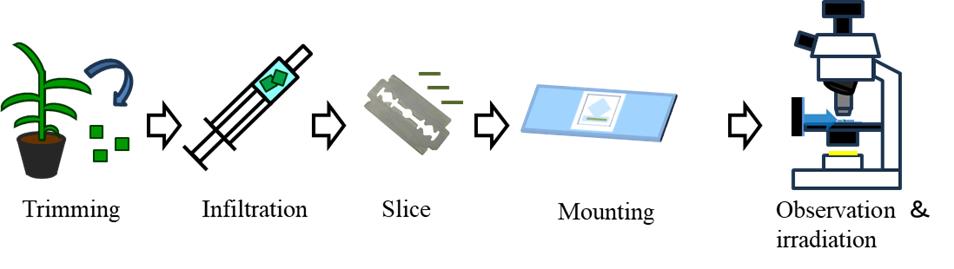
A. Infiltration of leaf segments using a syringe
Air in the intercellular spaces in leaf tissue interferes with light transmission and hinders microscopic observation. To remove air, use a syringe to alternately apply mild vacuum and pressure around the leaf.
1. On a silicon rubber plate, cut the leaf blade using a razor blade into approximately 5 × 5 mm segments, avoiding the midrib.
2. Put 2–4 leaf segments and approximately 1 mL of purified water into the syringe.
3. Expel the air from the syringe by pushing the plunger.
4. Seal the syringe tip with a finger and slowly pull back the plunger to induce a low-pressure environment. While keeping the tip sealed, gradually return the plunger to its original position.
5. While keeping the tip sealed, push the plunger to induce a high-pressure environment in the syringe.
6. Repeat the push and pull movements of the plunger until water infiltrates the leaf tissue, causing the leaf segments to darken in color and sink into the water (Video 1).

B1. Slicing the leaf segments using a vibratome
Embedding the leaf segment in agar and slicing it with a vibratome allows for the stable and consistent production of uniformly thick sections.
1. Add 100 mL of purified water and 5 g of agar to a 300 mL flask, then dissolve it using a microwave.
2. Pour the melted agar solution into a small-diameter glass Petri dish and cool it in an ice bath while stirring with tweezers until the solution reaches a highly viscous state, immediately before solidification (Video 2).
3. Insert one infiltrated leaf segment (5 × 5 mm) into the agar solution just before it solidifies, and then immediately place ice on top of the agar to accelerate cooling.
4. Once the agar is fully solidified, remove the dish from the ice bath and use the flat part of a spatula to lift the agar block out of the glass dish.
5. Trim the agar block with a razor blade, ensuring that the vascular bundle and the leaf plane are perpendicular to the bottom surface of the agar block (Figure 1A, B).
Note: If you want to observe a longitudinal section, you must align the vascular bundle horizontally with the bottom surface of the agar block.
6. Attach the agar block containing the leaf segment to the vibratome sample tray using instant adhesive and wait for at least 5 min to ensure complete solidification.
7. Set the tray to the vibratome (Figure 1C).
8. Fill the tray with water, set the desired thickness, and proceed with sectioning.
Note: The optimal thickness setting varies depending on plant species and growth conditions. In our experience, setting the thickness to approximately twice the size of the individual cells in the cutting direction helps balance the risk of structural disintegration owing to excessive thinness and loss of visibility caused by excessive thickness. For transverse sections of finger millet, we consider 100 μm to be the optimal thickness.
9. Place the cut leaf section in a drop of water produced by surface tension on an inoculation loop or on the tip of tweezers that are not fully closed, and then carefully transfer it to a water-filled Petri dish.
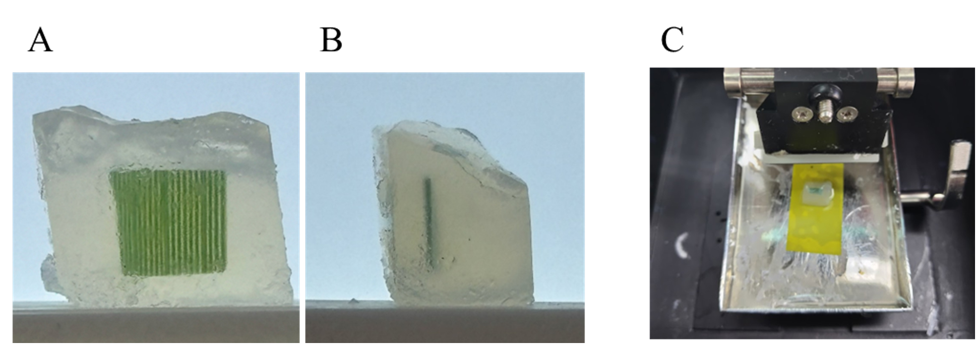
Figure 1. Slicing the leaf segment in the agar block using a vibratome. (A,B). Trimmed agar block containing leaf segments. The bottom surface of the agar block is perpendicular to the vascular bundles of the leaf (A) and the leaf plane (B). (C) Agar blocks glued to a tray in a vibratome.
Note: In unfixed sections, partial cell cutting leads to the expulsion of intracellular contents owing to turgor pressure, rendering the cells non-functional. This phenomenon can be utilized for the selective deactivation of cells based on size and shape differences between the cell types (Figure 2). In finger millet, the bundle sheath cells are thicker than the mesophyll cells in transverse sections (Figure 2A, B). Therefore, it is possible to selectively remove the contents of bundle sheath cells by making longitudinal slices that are thinner than the bundle sheath cells but thicker than the mesophyll cells. At 60 μm thickness, both bundle sheath cells and adjacent mesophyll cells remain intact (Figure 2C). At 40 μm thickness, bundle sheath cells lose their contents, while adjacent mesophyll cells remain intact (Figure 2D). However, if the section does not include vascular bundles, bundle sheath cells are also not included (Figure 2E); therefore, the relationship between the two cells cannot be verified. Precise targeting of vascular bundles during cutting is nearly impossible; therefore, it is necessary to verify the presence of vascular bundles after slicing. Although microscopic observation is required for a precise selection, sections containing vascular bundles tend to be slightly firmer in structure and less prone to deformation, allowing for a simple preliminary selection.
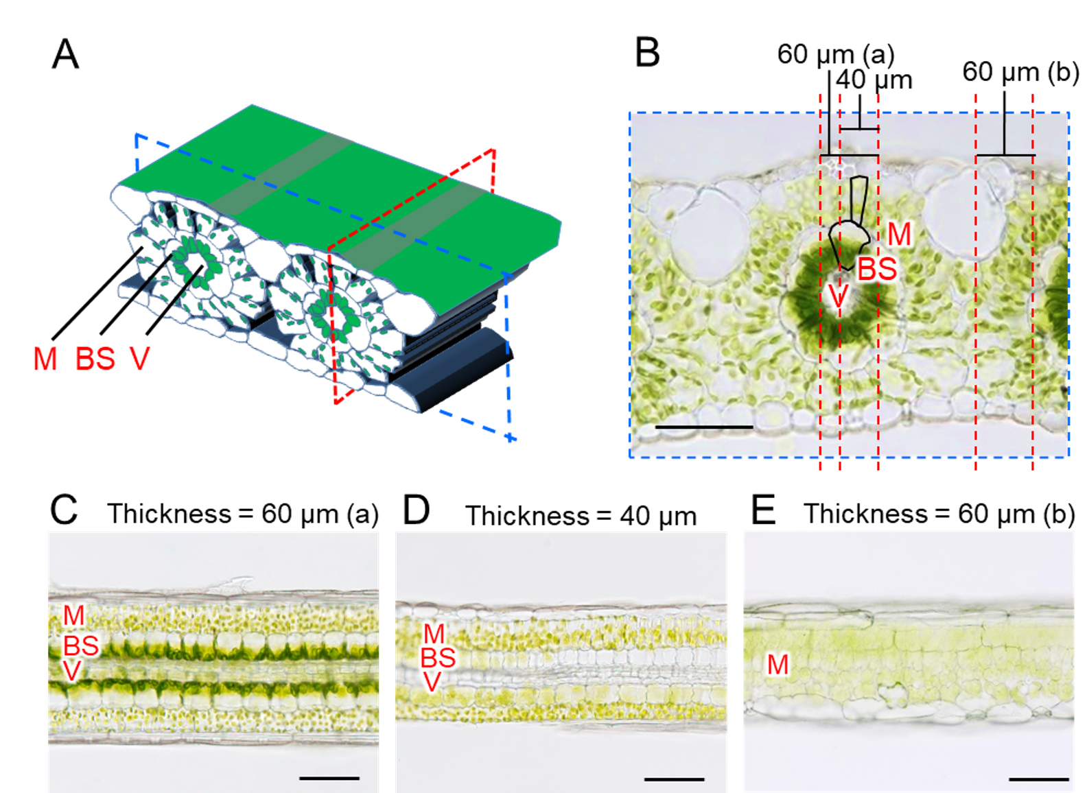
Figure 2. Selective removal of bundle sheath cells in C4 plants by longitudinal sectioning. (A) Schematic diagram of the leaf blade of finger millet. A transverse section was made by cutting the leaf blade perpendicular to the vascular bundle (blue dashed line), and a longitudinal section was cut parallel to the vascular bundle (red dashed line). (B) Microscope image of a transverse section. Since bundle sheath cells are larger than mesophyll cells, it is possible to cut only bundle sheath cells while leaving mesophyll cells intact. (C–E) Longitudinal sections. (C) 60 μm-thick section with intact bundle sheath cells. (D) 40 μm-thick section without bundle sheath cell contents. (E) 60 μm-thick section, not including the vascular bundle, obtained by sectioning at 60 μm. Depending on the location of the slice, most of the cells in the section are partially broken off. M, mesophyll cell; BS, bundle sheath cell; V, vascular bundle. Scale bars, 100 μm. This figure is based on Figure 4 from Kato et al. (2025) [7] with modifications and additions.
B2. Slicing the leaf segments by hand sectioning
Using the vibratome method, soft leaves (e.g., Arabidopsis thaliana) tend to fall apart during sectioning, whereas hard leaves (e.g., Camellia japonica) often detach from the agar. The hand-sectioning method overcomes these limitations by allowing sectioning regardless of leaf firmness. However, it should be noted that the thickness of the sections is not consistent.
1. Place the infiltrated leaf segment (5 × 5 mm) with approximately 1 mL of water on a translucent rubber plate and slice it into thin sections by pulling the blade while gently pressing the leaf with a finger (Video 3).
2. Check the quality of the leaf sections on a rubber plate (Figure 3).
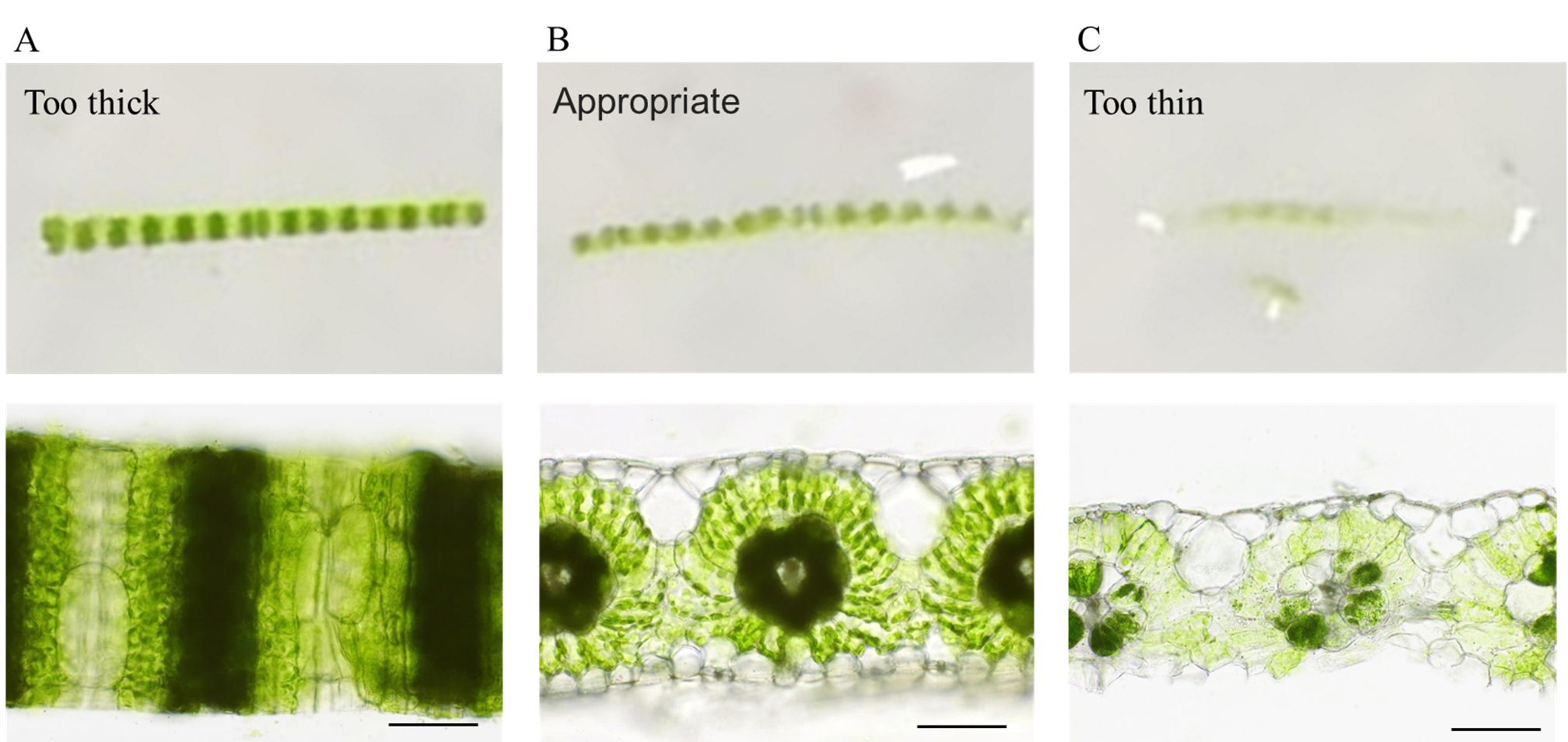
Figure 3. Appearance and microscopic images of hand sections from leaf blades of finger millet. (A) The slice thickness is greater than the leaf thickness. The cut surface does not face upward, and the leaf section is viewed from the epidermal side. (B) The slice thickness is appropriate. The cut surface is facing upward, and the leaf section maintains the gentle curvature of the leaf itself. (C) The slice thickness is thinner than most of the leaf cells. Some parts of the leaf tissue have collapsed. Scale bars, 100 μm.
3. Place the cut leaf section in a drop of water produced by surface tension on an inoculation loop or on the tip of tweezers that are not fully closed, and then carefully transfer it to a water-filled Petri dish.
Note: In hand-sectioning, the most critical step is not the cutting process itself but rather checking the quality of the leaf sections. To help assess the condition of the leaf sections, placing a white paper under a silicone rubber plate can brighten the background and improve visibility. If the visibility remains poor, using a light source such as a light table under the silicone rubber plate further increases the visibility.
C. Preparation of the microscope slide for live leaf-section imaging
Creating a frame with a silicone rubber sheet allows for stable, long-term observation by simply placing a cover glass that prevents water evaporation (Figure 4). Additionally, the use of a transparent silicone rubber sheet enables light irradiation through the rubber sheet to reach the epidermal surface of the leaf.
1. Cut the rubber sheet slightly larger than the cover glass with a razor blade or a utility knife. Then, cut a narrow rectangular groove for placing the leaf section and a larger square buffer space to slow liquid movement when sealed with a cover glass (Figure 4B).
2. Wash the rubber sheet and a glass slide, then rinse them with purified water. While still wet, place the rubber sheet at the center of the glass slide.
3. Wipe off excess water protruding from the rubber sheet with a paper wiper and allow the glass slide to dry at room temperature for at least 1 h.
Note: If drying is insufficient, the mounting liquid may seep between the glass slide and the rubber sheet, causing the sheet to lift. Ideally, a rubber sheet should be placed and left to dry the day before mounting.
4. Pour a thin layer of 0.1% agar solution into the groove created in the silicone rubber sheet, then carefully transfer the leaf section into the groove using an inoculation loop or tweezers (Video 4).
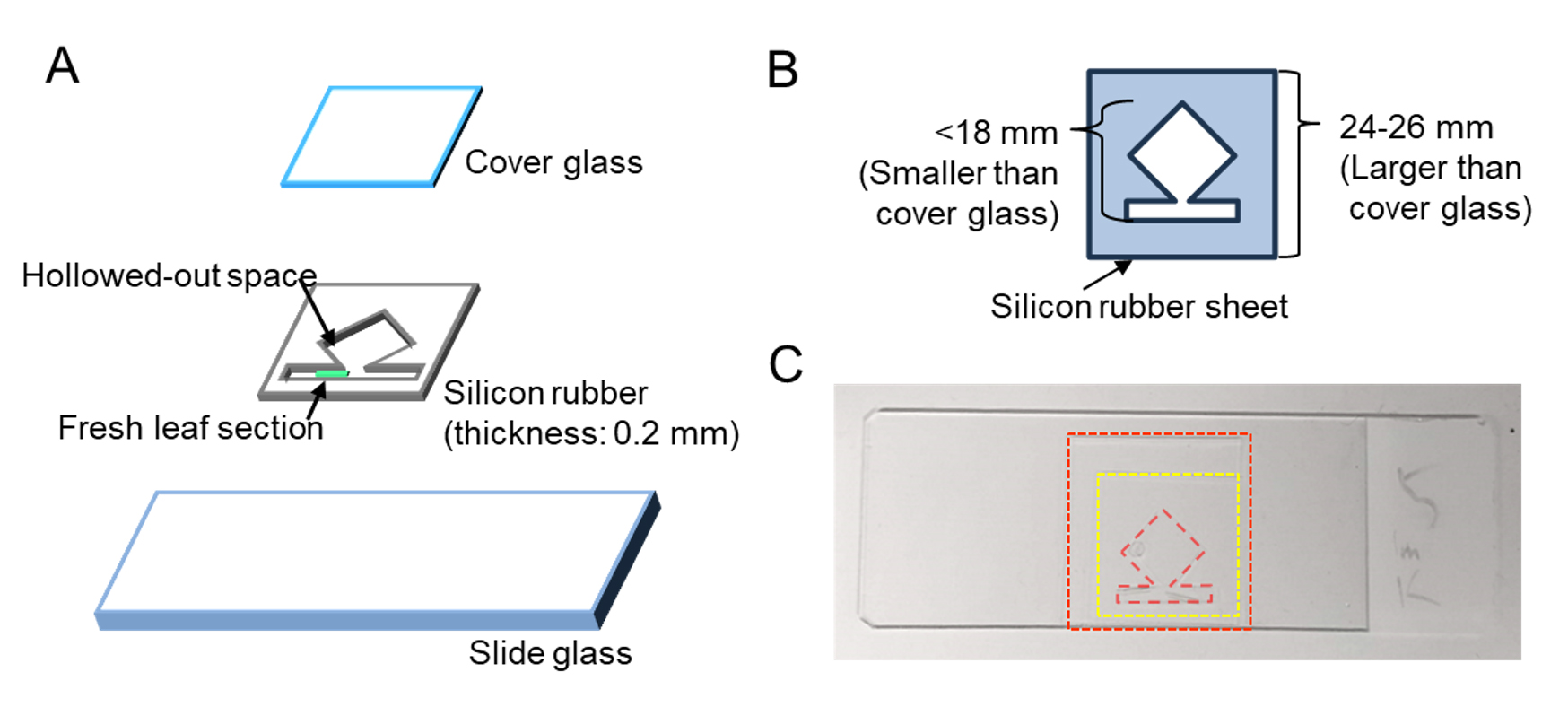
Figure 4. Slide preparation for long-term observation using a transparent silicone rubber sheet. (A) Composition of the live leaf-section mount. (B) Dimensions for cutting the silicone rubber sheet. (C) Top view of the microscope slide. This figure is based on a part of Supplementary Figure S1 from Kato et al. (2025) [7] with modifications and additions.
5. Adjust the orientation and alignment of the leaf section by gently pressing its edges with the tip of the tweezers.
6. Seal the sample with a cover glass.
Note: If the leaf section protrudes from the groove when sealed with a cover glass, the liquid volume is too high. Adjust the amount of liquid and attempt sealing again.
7. Wipe off excess water protruding from the cover glass with a paper wiper.
D. Microscopic observation under light irradiation to induce chloroplast movement
1. Place red filters after the microscope light and before the camera (Figure 5).
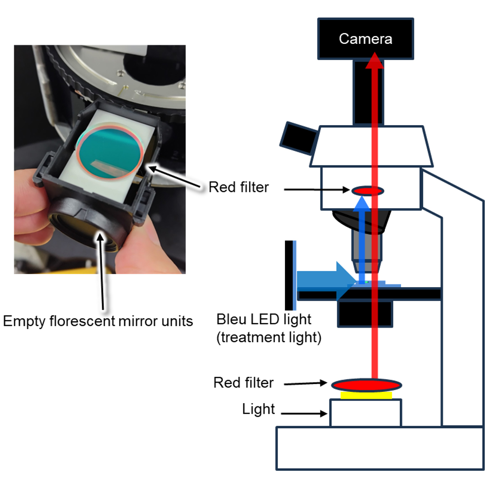
Figure 5. Schematic diagram of the live leaf-section imaging. Schematics and image of the optical path. Red filters are placed within the optical path of the microscope, after the light source and in front of the camera. Weak red light (less than 1 μmol·m-2·s-1) was used for observation. A red filter was placed over the light source. The red filter is installed in front of the camera in an empty fluorescence mirror unit of the microscope. This figure is based on part of Supplementary Figure S1 from Kato et al. (2025) [7] with modifications and additions.
2. Set the prepared microscope slide on the microscope and adjust the focus under dim red light.
3. Use the timelapse function of the camera software to capture images once per minute, continuing until the observation is complete.
Note: It is recommended to observe under only a dim red light for at least 1 h to allow the leaf to stabilize. If this step is skipped, there is a high probability that the focal position will shift or that the XY position of the leaf section will fluctuate during chloroplast movement induction. See Troubleshooting problem 2.
4. Place a light panel in front of the microscope to illuminate the leaf section through the rubber sheet.
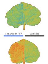
Note: For finger millet, chloroplast movement can be induced and completed by irradiating the sample with 500 μmol·m-2·s-1 of blue light for 4 h from the adaxial side (Video 5). The light intensity is measured by placing the light sensor at the same distance from the light source as the leaf section during observation. To properly control the light environment, observations should be conducted in a dark room.
E. Tracking chloroplast movement using Fiji
1. Launch Fiji (ImageJ).
2. Go to File → Import → Image Sequence.
3. Select the folder containing the time-lapse images and click Open.
4. Open an image that contains a known scale bar.
5. Select the Line Tool from the toolbar and draw a line along the reference scale.
6. Go to Analyze → Set Scale.
7. In the Set Scale window, enter the known distance in the Known distance field.
8. Go to Plugins → Tracking → Manual Tracking.
9. In the Manual Tracking window, set Time Interval to 1 min.
10. Click Add Track and manually click on the first chloroplast to start tracking. Continue clicking on the same chloroplast in each subsequent frame to track its movement over time.
Note: Chloroplasts also move along the Z-axis, which may cause them to move out of focus. Therefore, not all chloroplasts are continuously tracked throughout the observation period.
11. Repeat for other chloroplasts.
12. After tracking is complete, click End Track.
13. Save the result data by clicking File → Save As... and choose CSV format for further analysis in Excel or R.
14. (Optional) To visualize movement trajectories, use Plot Track in the Manual Tracking tool (Figure 6A).
Note: Using the coordinates of each chloroplast and the coordinates of the edges of the adjacent cell, the variation in the distance of the chloroplast from the neighboring cell can be calculated (Figure 6B, C). The linear distance from the bundle sheath (BS) cell in Figure 6C was calculated using the coordinates of each chloroplast at each time point (x0, y0), and the coordinates of the two endpoints (x1, y1) and (x2, y2) of the interface between the mesophyll and bundle sheath cells, all obtained using ImageJ. The formula is shown below.
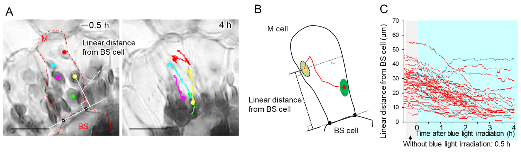
Figure 6. Tracking chloroplast. (A) Images of adaxial mesophyll cells at the start of observation (-0.5 h) and 4 h after irradiation. A dot indicates the chloroplast position at each observation time, and chloroplast movement up to that time is indicated by a line. The shortest distance between the center of the chloroplast and the tangent to the bundle sheath cell is the "linear distance from BS cell." (B) Schematic diagram showing changes in mesophyll chloroplast position. (C) Temporal changes in linear distance from bundle sheath cells in each chloroplast at each time were plotted at 1 min intervals from 0.5 before to 4 h after blue light irradiation treatment. If the chloroplasts could not be tracked because they overlapped or turned out of focus, tracking was terminated at that point. Red lines represent chloroplasts that moved closer to the bundle sheath cells, and the blue line represents those that moved farther from the bundle sheath cells after 4 h of blue light irradiation, compared to their initial position at the initial stage of irradiation (t = 0). The line colors were determined based on the tracking endpoint for chloroplasts that could not be tracked for 4 h after initiation of the blue light irradiation treatment. More than 10 chloroplasts were randomly selected for monitoring from the adaxial side of leaf sections taken from three plants (chloroplast number = 39). M: mesophyll cell; BS: bundle sheath cell. Scale bars, 25 μm. This figure is based on Figure 2 and a part of Figure 3 from Kato et al. (2025) [7] with modifications and additions.
Validation of protocol
This protocol or parts of it has been used and validated in the following research articles:
Kato et al. [7]. Bundle sheath cell-dependent chloroplast movement in mesophyll cells of C4 plants analyzed using live leaf-section imaging. Scientific Reports (Figure 2B, Figure 3B–D, Figure 5C, Supplementary Figure S2B and S2C, Supplementary Figure S3B, Supplementary Figure S4B, and Supplementary Figure S5B and S2C)
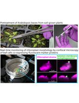
To minimize the influence of light other than the blue light used to induce chloroplast movement, red filters were used in Kato et al. [7]. However, the red filters are not essential. In Arabidopsis thaliana, avoidance movement and recovery were observed under blue light irradiation from the adaxial side even without a red filter (Video 6). If a red filter is not used, full-color imaging can be performed.
General notes and troubleshooting
General notes
1. In the cutting step, it is important that the blade is not pressed against the leaf sample to be cut but is pulled back to slice. This technique prevents tissue damage to the cut surface and ensures high-quality samples.
2. The mounting liquid does not have to be purified water. At least in finger millet, chloroplast movement was observed even in Good's buffer, such as HEPES (data not shown).
Troubleshooting
Problem 1: The sectioning is not successful.
Possible cause: The razor blade has lost its sharpness.
Solution: Change the razor blade edges to new ones. Ideally, a new blade should be used for each sample.
Problem 2: The leaf section shifts during observation.
Possible cause: Insufficient stabilization time or improper sealing.
Solution: Do not begin observation immediately after the preparation of microscope slides. Wait for at least 1 h for the leaf sections to stabilize on the microscope slides. If the shift persists, dust may be trapped between the silicone rubber sheet and the slide or cover glass, leading to water evaporation through the gaps. To prevent this, carefully wash all components before assembling.
Problem 3: Cell contents of the specific cell type (e.g., C4 plant bundle sheath cells) cannot be selectively removed.
Possible cause: Insufficient number of slicing attempts.
Solution: Precise control of the cutting position at the micrometer level is nearly impossible. Therefore, it is necessary to repeat the slicing process until a satisfactory section is obtained. In our experience, it is common to create more than 50 slices before successfully obtaining a single high-quality section.
Problem 4: Bubbles appear during observation.
Possible cause: Air dissolved in the mounting water may outgas over time.
Solution: In most cases, they occur at the corners of the silicon rubber sheet and are rarely obstructive to observation. If they are of concern, gently stir the mounting solution after melting to avoid introducing excess air, or degas the solution to reduce the amount of dissolved gas using a syringe.
Acknowledgments
The author (Y.K.) would like to take this opportunity to thank the Interdisciplinary Frontier Next-Generation Researcher Program of the Tokai Higher Education and Research System.
This study was supported by the Japan Society for the Promotion of Science (JSPS) KAKENHI. Grant numbers: JP20H02966 and JP23H02195 (to M.T.). Grant number: JP23K26799 (to Y.S.). Grant number: JP- MJSP2125 (to Y.K.).
The original research paper in which the protocol was described and validated is [7].
Competing interests
The authors declare no conflicts of interest.
References
- Yamada, M., Kawasaki, M., Sugiyama, T., Miyake, H. and Taniguchi, M. (2009). Differential Positioning of C4 Mesophyll and Bundle Sheath Chloroplasts: Aggregative Movement of C4 Mesophyll Chloroplasts in Response to Environmental Stresses. Plant Cell Physiol. 50(10): 1736–1749. https://doi.org/10.1093/pcp/pcp116
- Maai, E., Shimada, S., Yamada, M., Sugiyama, T., Miyake, H. and Taniguchi, M. (2011). The avoidance and aggregative movements of mesophyll chloroplasts in C4 monocots in response to blue light and abscisic acid. J Exp Bot. 62(9): 3213–3221. https://doi.org/10.1093/jxb/err008
- Kato, Y., Oi, T. and Taniguchi, M. (2023). Aggregative movement of C4 mesophyll chloroplasts is promoted by low CO2 under high intensity blue light. Plant Biol. 25(4): 563–570. https://doi.org/10.1111/plb.13512
- Wada, M., Kagawa, T., Sato, Y. (2003). Chloroplast movement. Annu Rev Plant Biol. 54: 455–468. https://doi.org/10.1146/annurev.arplant.54.031902.135023
- Wada, M. (2013). Chloroplast movement. Plant Sci. 210: 177–182. https://doi.org/10.1016/j.plantsci.2013.05.016
- Wada, M. and Kong, S. G. (2018). Actin-mediated movement of chloroplasts. J Cell Sci. 131(2): e210310. https://doi.org/10.1242/jcs.210310
- Kato, Y., Oi, T., Sato, Y. and Taniguchi, M. (2025). Bundle sheath cell-dependent chloroplast movement in mesophyll cells of C4 plants analyzed using live leaf-section imaging. Sci Rep. 15(1): 3447. https://doi.org/10.1038/s41598-025-86153-1
Article Information
Publication history
Received: Apr 18, 2025
Accepted: Jun 30, 2025
Available online: Jul 22, 2025
Published: Aug 5, 2025
Copyright
© 2025 The Author(s); This is an open access article under the CC BY-NC license (https://creativecommons.org/licenses/by-nc/4.0/).
How to cite
Kato, Y., Oi, T., Sato, Y. and Taniguchi, M. (2025). Live Leaf-Section Imaging for Visualizing Intracellular Chloroplast Movement and Analyzing Cell–Cell Interactions. Bio-protocol 15(15): e5404. DOI: 10.21769/BioProtoc.5404.
Category
Plant Science > Plant cell biology > Cell imaging
Cell Biology > Cell imaging > Live-cell imaging
Plant Science > Plant cell biology > Cell structure
Do you have any questions about this protocol?
Post your question to gather feedback from the community. We will also invite the authors of this article to respond.