- Protocols

- Articles and Issues
- For Authors
- About
- Become a Reviewer

Analysis and Quantification of Functional Regeneration of Dendrite and Axon of PVD Neuron After Laser Injury in Caenorhabditis elegans
Published: Vol 15, Iss 8, Apr 20, 2025 DOI: 10.21769/BioProtoc.5280 Views: 2265
Reviewed by: Sravanthi S P NadimintiAnonymous reviewer(s)
Original research article
The authors used this protocol in:

May 2024
Advertisement


Protocol Collections
Comprehensive collections of detailed, peer-reviewed protocols focusing on specific topics


Related protocols
Abstract
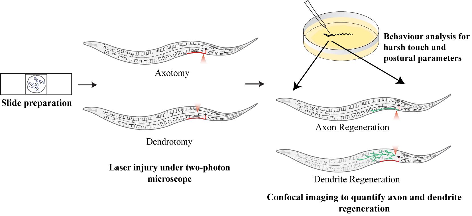
Research into nervous system injuries and regeneration has emerged as a crucial field of study. In many cases such as trauma or stroke, both axons and dendrites are equally damaged; however, studying injury and repair mechanisms in both neurite processes (axons and dendrites) of the same neuron has been challenging. Additionally, correlating the behavioral aspects of neuronal injury with anatomical regeneration is important for a better understanding of the functional rewiring process. Here, we describe protocols for injuring the dendrites and the axon of the PVD neuron of C. elegans using a two-photon infrared (IR) femtosecond laser system, and subsequent imaging of injured neurites during the course of regeneration. Additionally, we describe the protocols for the behavioral study concerning the PVD neuron and their analysis, which can offer valuable insights. These assays can be implemented to assess the function of the pathways that play specific roles in dendrite vs. axon regeneration.
Key features
• Dendritic and axonal injury in PVD neurons using a two-photon microscope.
• Behavioral analysis involving harsh touch response and proprioception following neurite injury.
• Correlation of dendrite and axon regeneration events with behavioral parameters.
Keywords: C. elegansGraphical overview
Background
The structure and function of dendrites play a crucial role in the processing and integration of the input signal from synapses. While the severing of axons, their regeneration responses, and repair, along with their impact on associated behaviors, have been widely studied in Caenorhabditis elegans as well as other organisms [1–5], much less is known about the mechanisms underlying dendrite regeneration. Although both dendrites and axons are structurally and functionally distinct, they are part of the same cell, and both play important roles in the transmission of information. Thus, to comprehend the molecular mechanisms that may be involved in the regeneration events of both dendrites and axons, as well as how they vary, it is necessary to investigate both of them in the same neuron. Therefore, developing protocols for targeted dendrite injury is crucial to bridging the knowledge gap involving dendritic response to injury and its impact on behavioral outcomes. Dendrites present a unique challenge as they are thinner, more fragile, and more branched than axons, making their precise severing difficult [6,7]. Additionally, dendrites receive input as graded potential, as opposed to the transmission of input as action potential through the axon. This imparts another level of complexity in information processing, rendering challenges in studying the functional aspect of dendrite regeneration. Also, dendrotomy protocols must be carefully developed to allow for targeted and reproducible dendritic injury with minimal collateral damage. Laser-based techniques have been highly successful in axotomy and could potentially be adapted for dendrotomy as well [6,8]. Femtosecond lasers offer the precision necessary for severing an individual neurite [5,9–12]. Moreover, advancements in imaging technologies such as high-resolution confocal and multiphoton microscopy make it easier to manipulate both the axon and dendrites of the same neuron in C. elegans model [6,13]. However, no systematic protocol for performing dendrotomy and subsequent study of dendrite regeneration events currently exist for C. elegans, implying the need for innovation in this area.
Here, we have outlined both axotomy and dendrotomy protocols using a femtosecond laser in a two-photon microscope, which is adapted from a recent study in PVD neurons labeled with the genetically encoded green fluorescent protein (GFP) [13]. This protocol has been used to quantify various parameters involving dendritic responses to injury, their remodeling, and the impact on the behavioral outcomes related to the PVD neuron [6]. This protocol allowed researchers to compare the roles of molecular pathways in dendrite and axon regeneration post-laser surgery [6,13]. The PVD neuron acts as a multisensory neuron, which controls both nociceptive touch sensation and body posture or proprioception [14]. The dendrites are known to play a role in proprioception and axons relay the information about nociceptive stimuli. We used assays based on these two sensory behaviors for the functional assessment of dendrite and axon regeneration events [13]. Potentially, this approach could lead to the discovery of novel genes and pathways that specifically regulate dendrite repair, further expanding our understanding of neuronal plasticity and repair mechanisms.
Materials and reagents
Biological materials
1. C. elegans strains (wdIs52)(F49H12.4::GFP) expressing GFP in the PVD neuron. The C. elegans strains utilized in this work were obtained from the Caenorhabditis Genetic Center (CGC) in Minneapolis, USA. Please refer to wormbook.com for fundamental worm culture procedures
2. OP50 E. Coli bacteria obtained from CGC USA
Reagents
1. Sodium chloride (NaCl) (Sigma, catalog number: 71376)
2. Tryptone (TM Media, catalog number: 3514)
3. Peptone (TM Media, catalog number: 1506)
4. Agarose (Sigma, catalog number: A9539)
5. Agar agar type 1 (TM Media, catalog number: 242M)
6. Cholesterol (Sigma, catalog number: C8667)
7. Levamisole hydrochloride (Sigma, catalog number: L0380000)
8. Calcium chloride (CaCl2) (Qualigens Fine Chemicals, catalog number: 22205)
9. Magnesium sulphate heptahydrate (MgSO4.7H2O) (Merck, catalog number: 193645)
10. Potassium phosphate monobasic anhydrous (KH2PO4) (Merck, catalog number: 193205)
11. Absolute ethanol (Merck, catalog number: 100983)
12. Sodium phosphate dibasic anhydrous (Na2HPO4) (Merck, catalog number: 193609)
13. Ammonium Chloride (NH4Cl) (Merck, catalog number: 193621)
Solutions
1. Nematode growth medium (NGM) plates (see Recipes)
2. B broth (see Recipes)
3. OP50 culture (see Recipes)
4. 5% agarose solution (see Recipes)
5. M9 buffer (see Recipes)
Recipes
1. Nematode growth medium (NGM) plates
For preparation of 1 L of media, add 3 g of NaCl, 2.5 g of peptone, and 20 g of agar to 700 mL of MilliQ water; then, bring up the volume to 1,000 mL. Autoclave the media, let it cool down to 55 °C, and add the following solutions after filter sterilization using a 0.22 μm filter: 1 mL of cholesterol (10 mg/mL prepared in absolute ethanol), 1 mL of 1 M CaCl2, 1 mL of 1 M MgSO4.7H2O, and 25 mL of 1 M KH2PO4 under sterile conditions. Mix well and pour media into 60 mm Petri plates with 10 mL of media per plate. Keep at room temperature for 24 h and then store at 4 °C for later use.
2. B broth
Add 0.5 g of tryptone and 0.25 g of NaCl to 50 mL of MilliQ water. Autoclave and store it at 4 °C.
3. OP50 culture and seeded NGM plates
Thaw the OP50 bacteria from its glycerol stock by streaking it onto an NGM plate. Incubate this plate at 37 °C for 12 h. Using a sterile tip, pick one colony of OP50 bacteria from the freshly streaked plate and place it into autoclaved B broth. Incubate it overnight at 37 °C. Use this liquid culture for seeding the NGM plates for worm growth and maintenance. Parafilm the freshly streaked plate of OP50 and the liquid culture in B broth and store in a 4 °C refrigerator. This liquid culture can be used for up to 2 weeks.
From the cultured media, pour around 5 mL in a sterile 60 mm plate. Take a sterile glass L-shaped rod, dip in the culture of OP50 in the 60 mm plate, and use this L rod to spread the culture in a square patch on the sterile NGM plate. Sterilize the L rod over a flame in between spreading on multiple plates. Incubate these plates at 37 °C for 10–12 h so that a thin square-shaped patch of OP50 bacteria grows. These plates are used for regular worm maintenance.
To create a uniform lawn for behavioral experiments, pour around 100 μL of cultured OP50 on the sterile NGM plates and spread the culture onto the plate by swirling the Petri plate. Do not put the lids on until the culture has dried completely. Incubate these plates at 37 °C for 10–12 h so that a uniform circular lawn appears on the plates. These seeded plates can be stored at 15 °C for a week.
4. 5% agarose solution
Weigh 0.15 g of agarose in a test tube. Add 3 mL of 1× M9 buffer to it. Hold the test tube with the test tube holder and heat it up on a Bunsen burner or spirit lamp until the solution boils. Keep that test tube in the heating block set to 60 °C for 5 min to remove bubbles. When bubbles in the solution are cleared up, use it for making slides. Keep that test tube in the heating block until the experiment is done.
Note: Make sure to use a solution clear of bubbles as they may hinder imaging. Make fresh agarose solution every time imaging or injury experiments are to be conducted.
5. M9 buffer
For preparing 5× M9 buffer, add the following salts to make their final concentration as mentioned: 0.1 M KH2PO4, 0.2 M Na2HPO4, 0.04 M NaCl, and 0.1 M NH4Cl. Mix the salts (heat to 60–65 °C if needed). Autoclave the solution and store it at room temperature. Dilute the solution to 1× using MilliQ water for agarose preparation.
Laboratory supplies
1. Test tube, 5 mL (Praveen Scientific Corporation, catalog number: 40487)
2. Tips [Tarsons, catalog numbers: 521000 (10 μL), 521010 (200 μL), 521016 (1,000 μL)]
3. Filter tips, 200 μL (Tarsons, catalog number: 527104)
4. Micropipette [Gilson, catalog numbers: F144054M (P2), F144056M (P20), F144058M (P200), F144059M (P1000)]
5. Disposable sterile Petri dishes, 60 mm (Praveen Scientific Corporation, catalog number: 20440)
6. Glass slides (Blue Star, PIC 1.75 mm long × 25 mm wide, 1.35 mm thick)
7. Coverslips (Blue star, 0.13 mm thick, 18 mm square)
8. Thin glass capillary (World Precision Instruments, catalog number: TW150-6)
9. Rubber tube (7 mm outer diameter, 4 mm inner diameter)
10. Butterfly scalp vein set (HMD, 22G × 19 mm)
11. Erlenmeyer flask (Borosil Scientific)
12. Measuring cylinder (Borosil Scientific)
13. Pasteur pipette (VWR, catalog number: 612-1798)
14. Spatula
15. Rubber bulb
16. Permanent marker
17. Worm pick of platinum wire with 99.99% purity of 0.15 mm diameter for the harsh-touch stimuli and 0.3 mm diameter for regular worm picking
Equipment
1. Weighing balance [Sartorius, model: BSA224S-CW, 220 g(max), d-0.1 mg]
2. Laminar flow hood (Atlantis)
3. Luer connector (isolated from the butterfly scalp vein set)
4. Stereomicroscope (Nikon, model: SMZ745, zoom 5× max)
5. Leica stereomicroscope with attached camera for taking videos and still images of the worms over the NGM plate (Leica, model: M165FC), zoom 12× max, attached camera (Leica, model: MC120HD), resolution 2.5 megapixels (1,216 × 912), pixel size 3.34 μm, field of view 15 mm × 15 mm required for harsh touch videos
6. Two-photon microscope (Bruker ULTIMA multiphoton microscopy system) coupled with two spectra-physics, tunable infra-red femtosecond lasers (λ = 690–1,040 nm) having automated dispersion compensation (MaiTai with DeepSee), Conoptics Pockel cells with microseconds temporal resolution to control the output of the laser, two independent X-Y scan galvanometer mirrors for simultaneous imaging and cutting (6 mm scan galvanometer for imaging, 3 mm scan galvanometer for cutting). Imaging laser set at 920 nm with 50 fps (frames per second) pulse width, cutting laser set at 720 nm with 80 fps pulse width, irradiation time 20–30 ms, laser power 23 mW, lateral point spread function (PSF) ~400 nm, Z axis PSF ~1.5 μm, 60× Olympus water immersion objective (60×, 0.9 NAP). The IR femtosecond lasers can be switched on from MaiTai SpectraPhysics software (Figure 1E) or from the Prairie View software itself. The resting wavelength at which the lasers are switched on or off is 820 nm. Pockel-1 is used as a controller for primary laser power (used for imaging) (Figure 1E), which is present in the main home tab of Prairie View software. The output signal is detected by the photomultiplier tube (PMT) detector unit (green and red). The cutting laser is controlled by Pockel-2 (Figure 1E). The cutting laser controls reside in the electrophysiology tab in Prairie View software, where the power of the cutting laser and pulse duration can be tweaked
7. Confocal microscope (60×/1.4 NA oil objective of Nikon A1R confocal system for GFP imaging: 488 nm laser; for RFP imaging: 543 nm laser; intensity 4.0 and gain 48.3; pinhole set 1.0 AU; using AX galvanometer scanner with up to 8,192 × 8,192 pixels, 10 fps speed, 512 × 512 resolution image acquisition, dwell time 2 ms, averaging 2 frames, frame time 7.0 s, FITC scan mode, NPARC detector unit for imaging, Z-stack image acquisition at range of 25 μm, slice thickness 1 μm)
8. Worm incubator at 20 °C
9. Bacterial incubator at 37 °C
10. Worm pick platinum wire
11. Eyelash pick
12. Heating block kept at 60 °C (Neolab, model: TC544)
Software and datasets
1. Leica microscope software LAS V4.12
2. Prairie View software for two-photon microscope v5.4
3. MaiTai Spectra-Physics software
4. Nikon imaging software (NIS) Elements-C (imaging software)
5. ImageJ FIJI (analysis software)
6. GraphPad Prism v10.2.3
Procedure
A. Dendritic and axonal injury using two-photon microscope
1. Preparation of anesthetizing solution: prepare a 10 mM Levamisole solution in 1× M9 buffer.
Note: This solution can be used for a week when stored at 4 °C.
2. Assembling mouth pipette (Figure 1A): A mouth pipette is needed to transfer the axotomized or dendrotomized worms from the agar pad to the NGM plate after neurosurgery.
a. To make a mouth pipette, take a rubber tube and plug it with a luer connector (removed from the scalp vein set) at one end.
b. Pull a thin glass capillary over a flame to create a pointed end. (Gently rub the pointed ends of these capillaries with each other to create breaks. Use the capillary with smooth edges in the conical end.)
c. Heat the other end of the capillary over a flame and use it to perforate the cap of the luer connector.
d. Attach the pointed end of the 200 μL filter tip to the other end of the rubber tube.
e. Use the filter tip to gently apply suction force and use the capillary end to pick up worms suspended in 1× M9 buffer.
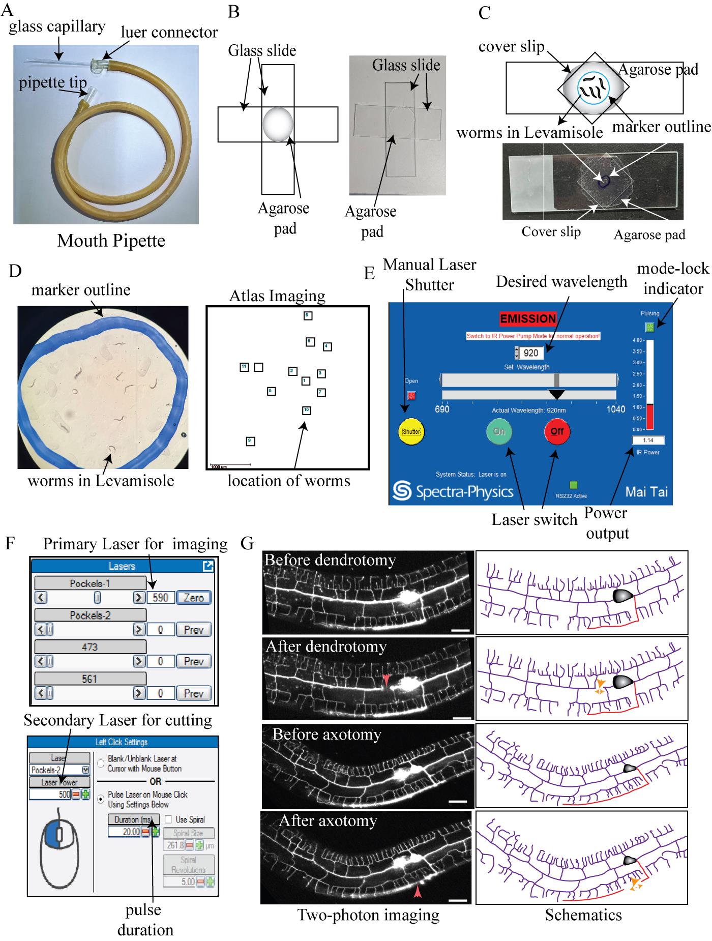
Figure 1. Preparation of worms and induction of dendrite and axon injury using a two-photon microscope. (A) Mouth pipette used for recovering the worms after injury. (B) Picture and schematics of the agarose pad made by the mounting of two glass slides. (C) Picture and schematics of the slide prepared for the two-photon cutting experiment. (D) Zoomed picture and Atlas Imaging panel representing the location of the worms saved on the Prairie View software. (E) Screenshot of the Laser control panel from Maitai Spectra-Physics software showing the controls of the laser switch, manual shutter, power output, and mode-lock indicator. (F) The upper panel represents the control of the imaging laser using Pockels-1, which is present under the main Prairie View software window. The lower panel represents the control of the cutting laser power using Pockels-2 along with the duration of the pulse laser. This panel is present under the electrophysiology tab of Prairie View software. (G) Schematics and two-photon imaging of worms before and just after the laser injury. The upper two represent dendrotomy; the bottom two represent the axotomy. A clear gap after injury is labeled with an orange dashed double arrowhead in the schematics. The site of injury is labeled with red arrowheads on the images and orange arrows on the schematics. The scale bar represents 20 μm.
3. Preparation of the agarose slide (Figure 1B)
a. Take the Pasteur pipette and mount a rubber bulb over the top.
b. Crush the thin part of the Pasteur pipette using pliers to widen its neck.
c. Using this Pasteur pipette, draw agarose solution and put a drop onto a clean glass slide.
d. Mount another glass slide over it and press it gently until it spreads evenly.
Note: Avoid the formation of bubbles in the agarose pad.
e. Keep the slides together for 1 min.
f. Gently remove the glass slide so that the agarose pad remains on one slide.
g. Label the slide with the agarose pad and use it for mounting worms.
4. Mounting worms on agar bed for neurosurgery (Figure 1C)
a. Take 2–4 μL of 10 mM levamisole solution and place a drop over the freshly prepared agarose pad.
b. Using the worm pick, pick the appropriate aged worms (L4 or Day 1 adults) from a growing NGM plate.
Note: An eyelash pick may also be used if the worms are sick. Take approximately 15–20 worms per slide for laser injury.
c. Place that worm pick in the levamisole solution on the agarose pads until the worm swims off the pick.
Note: Do not apply too much pressure to avoid creating irregularities in the agarose pad, which can cause worms to move while imaging or interfere with the injury procedure.
d. Wait for 30 s for the worms to get immobilized.
e. Place a coverslip over the worms, leaving a pointy overhang (Figure 1C).
Note: This coverslip configuration allows worms to be recovered without any damage after an injury by grabbing the cover slip overhang.
f. Using a marker, mark the boundary of the worms on the slide on the side opposite to the coverslip to avoid injuring the worms (Figure 1C). This helps in locating the worms under the two-photon microscope (Figure 1D).
5. Laser injury using a two-photon microscope (Figure 1D–G)
a. Switch on the lasers manually from the Prairie View or MaiTai software and wait until they get mode-locked at 820 nm.
Note: While switching on or off, the laser’s resting wavelength should be 820 nm as this is the buffer wavelength.
b. Set the primary or imaging laser at 920 nm (for imaging GFP-labeled neurons) or 1,020 nm (for imaging the RFP-labeled neurons).
c. Set the secondary or uncaging laser at 720 nm (for injuring the neurons).
d. Wait for the lasers to get mode-locked (Figure 1E).
Notes:
1. Achieving the mode-lock status is necessary before continuing with the experiment.
2. For more technical details, please see the Equipment section.
e. Apply a drop of MilliQ water on the coverslip to the marked region and place the slide on the two-photon microscope stage.
f. Using the z-control of the microscope, focus on the plane of agarose under a 60× water (0.9 NA) immersion lens.
Note: Do not let the lens touch the surface. When it touches the water droplet, use the eyepiece to focus it further.
g. Using the Atlas Imaging tool in the Prairie View software linked to the two-photon microscope, locate the worms and add the location of each worm in the white light imaging (Figure 1D).
h. When all locations are added, change the turret position to the laser mode and shut down the main shutter of the microscope.
i. Switch off the room's lights to avoid interference with PMTs and start the live scan over the Prairie View software.
j. Locate the PVD neuron by going to the mapped location in Atlas Imaging using x, y, and z controls or by simply clicking on it.
k. For dendrite injury, set the desired region around 20–50 μm from the cell body.
l. In the electrophysiology tab, set power to 400–500 and time duration to 10–20 ms (Figure 1F).
m. Point the crossover cursor over the site of injury and then click mark point.
n. After a few seconds, the GFP of that site will disappear, indicating that a break in the dendritic structure or injury has been done (Red arrow pointing downward, Figure 1G).
Note: A bright horizontal bar in the imaging window signifies that that laser has been shot.
o. Make another site of injury at around 5 μm from the previous laser shot to create a tandem break of around 10–15 μm. This paradigm is followed for dendrite injury since the proximal and distal dendrites often fuse following one injury [15] precluding the study of the branching response following dendrotomy.
p. Repeat this process by locating all worms that were tagged in the Atlas Imaging.
6. Recovering the worms after the injury experiment
a. Remove the slide from the two-photon microscope and take it under the stereoscope.
b. Remove the coverslip gently without squishing the worms.
c. Using the mouth pipette, apply suction pressure to aspirate the M9 buffer in it.
d. Pour the M9 buffer on the agarose pad containing worms and wait until the worms get suspended in it.
e. Gently aspirate the M9 buffer containing the injured worms and transfer it onto a freshly seeded NGM plate.
f. Keep these recovery plates in the worm incubator at 20 °C.
Note: The recovery period can vary according to the desired time point, i.e., 7, 12, and 24 h after injury.
B. Behavioral imaging and data acquisition
1. Preparing the plates for behavioral experiments (Figure 2A)
a. Using a pipette, transfer approximately 100 μL of the OP50 E. coli culture onto the NGM plates in the laminar hood, swirling to ensure even distribution.
b. Keep these spotted plates in the bacterial incubator for around 10–12 h.
Note: The bacterial lawn should be uniform as compared to the seeded plate, where colonies are visible. This allows for proper visualization of the worm tracings, which can be impeded in a non-uniform lawn. This should be prepared before the start of the experiment (Figure 2A).
c. Verify that the worms are moving normally after the proper recovery period, which may be 6–7 or 24 h following damage. Typically, 80%–90% of worms move normally, indicating less collateral injury due to the laser.
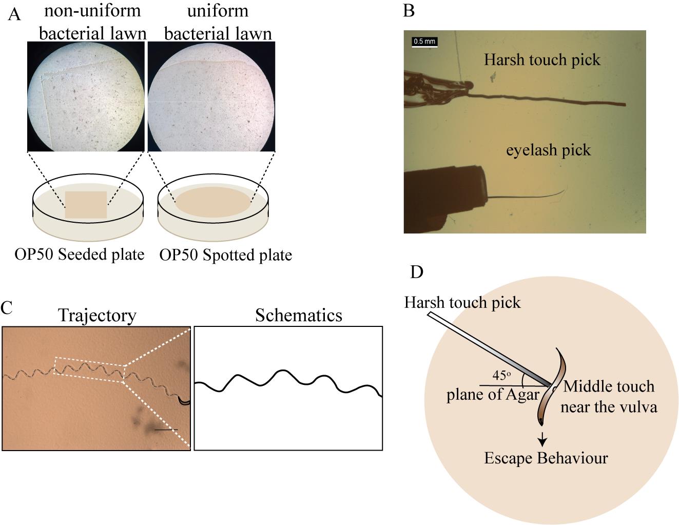
Figure 2. Behavioral experiments on recovered worms post-injury, including posture (proprioception) and harsh touch (nociception) analyses. (A) Seeded and spotted plates, showing the difference in the uniformity of the OP50 culture. (B) Harsh touch pick and eyelash pick images taken under the stereomicroscope. (C) Trajectory tracing in black dashed line along with zoomed trajectory schematics, showing the sinusoidal wave pattern. The scale bar represents 1 mm. (D) Angle and location where the worm is to be stimulated with harsh touch pick.
d. Making the eyelash pick.
i. Pluck an eyelash from the upper or lower lid of the eye.
ii. Fix the blunt end of the eyelash to the tip of the Pasteur pipette using adhesive tape.
iii. Using a pair of scissors, carefully cut the thin end of the eyelash to make it blunt (Figure 2B).
e. Making the harsh touch pick.
i. Cut a few centimeters of a thin platinum wire of 0.15 mm diameter.
ii. Fix one end of the wire with the glass Pasteur pipette by melting it over the flame.
iii. Take the small plier and press the other end of the pick sticking out of the pipette to flatten it (Figure 2B).
Note: Make sure the dimensions of the tip of the harsh touch pick are 0.15 mm in diameter as compared to the normal diameter of 0.3 mm for normal worm picking.
2. Postural data acquisition
a. At the desired time point, either at 6–7 or 24 h after injury, pick up the worms from the recovery plate and place each worm onto a separate OP50 E. coli spotted plate using an eyelash pick (Figure 2B). Since we immobilize the worms using Levamisole, it usually takes 7 h for worms to display normal locomotion. Therefore, we follow this minimum 6–7 h recovery period before performing the behavioral assays.
b. Keep these plates aside for 3–5 min, during which worms will leave a sinusoidal trail on the OP50 lawn (Figure 2C).
c. Using a Leica stereomicroscope with LASV4.12 software, capture an image of the sinusoidal trajectory of the worm at 1.2× magnification and note down which side of the worm is up (left side or right side) (Figure 2C).
d. Flip the worms to the other side using an eyelash pick and let them crawl for 3–5 min.
e. Take snapshots of the trajectories of the other side of these freely moving worms.
3. Harsh touch response data acquisition
a. Place each worm that underwent dendrotomy or axotomy in the spotted NGM plate with an eyelash pick and let it crawl for 3–5 min until it settles down.
Note: The resting period for worms to settle is essential as it removes foraging factors that might impact basal behavior. The eyelash pick is better to be used in the harsh touch response as it does minimal damage to the worms compared to the platinum wire pick.
b. Start recording the video using LSM software LAS V4.12 at 1.2× zoom while the worm is in the field of view at 10 fps minimum capturing speed.
Note: The frame speed was determined by analyzing 30 frames both before and after the application of harsh touch stimuli.
c. Using a harsh touch pick, touch the middle part of the worm (near the vulva) at an angle of 45° to the plane of the plate (Figure 2D).
Note: Avoid touching worms at a 90° angle as it would squish the worms and damage them. Avoid doing multiple touches. If the touch is improper, discard the video and start over with a new, untouched worm.
d. Start the video recording before the harsh touch and finish it after the harsh touch response until the worm is out of the field of view (Video 1).
Note: Avoid moving the plate during the recording process since this may interfere with the speed analysis of the recorded video.

C. Imaging of the recovered worms and data acquisition
1. Preparation of agarose slides
a. As described earlier, prepare the slides by taking 2 μL of 10 mM Levamisole and pouring multiple drops onto the agarose pad so that there is one worm per drop on an agarose pad.
Note: Limit to six worms per agarose pad. Too many worms can make it harder to find individual worms, especially if they need flipping to image the injured neurons after dendrotomy and axotomy.
b. After performing the behavioral assays, pick the worms with the eyelash and put them into separate drops (Figure 3A).
c. Pay attention to which side of the worm is up. If it is not the specific operated side for dendrotomy or axotomy, flip them using an eyelash pick to get the desired side up for confocal imaging (Figure 3B).
d. Once the desired sides are up, put the coverslip over them.
e. Mark the location of each worm on the side of the slide opposite to the coverslip (Figure 3A).
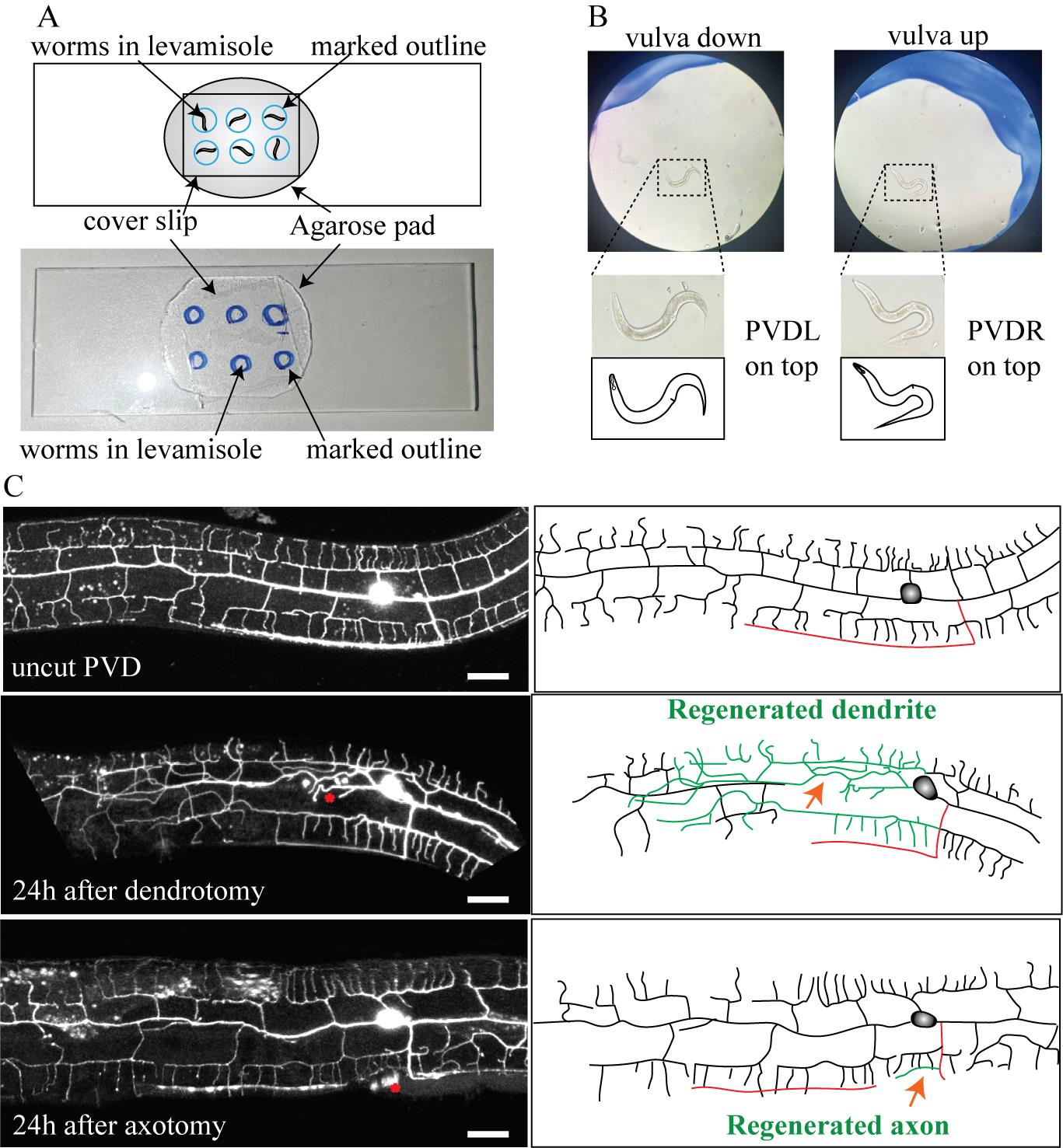
Figure 3. Anatomical visualization of dendrite and axon regeneration through confocal imaging. (A) Image and schematics of the slide containing worms for imaging; the blue circle represents the site where the worms are placed. (B) Zoomed image illustrating the orientation of the worms. On the left, the image shows the vulva-down orientation with PVDL (PVD neuron on the left side) on the top. On the right, the image represents the vulva-up orientation of the worm, with PVDR (PVD neuron on the right side) on the top. (C) Confocal images and schematics of the uncut PVD neuron, 24 h after dendrotomy and 24 h after axotomy. The red asterisk and the red arrowhead mark the site of injury in the confocal images and schematics, respectively. In the schematics, red represents the axon, green represents the regenerating neurite, and black represents uncut dendrites. The scale bar represents 20 μm.
2. Imaging using the confocal microscope
a. Put a little drop of oil on the coverslip over the marked regions of the slide.
b. Locate the worms using the marked sites.
c. Focus the worm with an eyepiece with 60× or 100× oil lens.
d. Shift the turret to the laser mode, using a 422 nm laser for imaging the GFP and 543 nm laser for RFP-labeled neurons.
Note: For technical details, please see the Equipment section.
e. Open the Z-stack imaging and set the first and last slice of the z-stack to include whole-PVD neuron.
Note: Make sure to include the primary and higher-order dendrite branches including menorahs and the axon of the PVD neuron.
f. Set the thickness of each slice to 1 μm and start capturing the Z-stack. Once capturing happens, save it in the desired location.
g. By doing the maximum projection of the z-stack, you can visualize the regeneration phenomena post-dendritic injury as well as axonal injury (Figure 3C).
Note: Depth coding for these images is necessary to analyze the reconnection event between the regenerating proximal dendrite and the distal dendrite. See the Data analysis section for more information.
h. Repeat for each recovered worm and save it in the desired location.
Data analysis
1. For the quantification of postural parameters, open the still images of the trajectory in ImageJ FIJI software. Create ROIs using the rectangle tool on the trajectory images of the worm. Duplicate the selected ROI from the image using command Ctrl + D. Use the line segment tool to measure the amplitude and wavelength of the trajectories (Figure 4A) and save these selected ROIs as a list using command Ctrl + t. Click on the measure tab in the ROI manager. (ROI manager can be accessed from Analyze > Tools > ROI Manager.) If the images are not calibrated, the value will be in the form of pixels. In such a situation, you need to convert it into micrometers using the scale at the same zoom. If the Leica software is properly calibrated, then data will be saved in micrometers. For the measurement of the angles, use the angle tool of ImageJ and make the three points as shown in Figure 4A. Save these ROIs and their measurements in the form of Excel sheet data points. For statistical analysis of postural parameters for each dataset, normality tests are done. A comparison between two groups (uninjured and injured) is performed using students’ t-test; a comparison between multiple groups is done using ANOVA with Tukey’s multiple comparisons method.
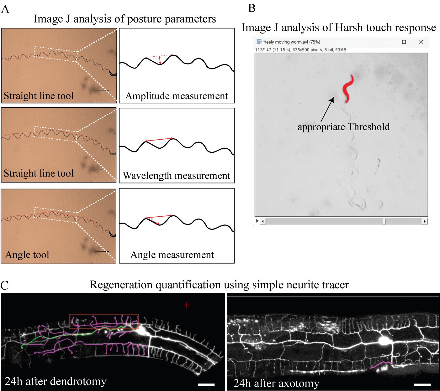
Figure 4. Data analysis for behavioral experiments and anatomical regeneration after dendrotomy and axotomy. (A) Images and schematics of the sinusoidal trajectories of the worms, along with the amplitude (top), wavelength (middle), and angle measurements (bottom). In the schematics, magenta indicates the measurements. (B) Thresholding of the worm in the harsh touch video; only the worm area is highlighted for optimum thresholding. (C) Snapshot of the simple neurite tracer of the regenerated dendrites and axon. The left panel illustrates the regenerated dendrites 24 h after dendrotomy. Regenerated branches are illustrated in pink. The regenerating branch that covers the maximum length is termed territory length and is illustrated in green. Menorah-menorah fusion, a phenomenon where multiple menorahs connect with more than one secondary, is marked by the red rectangle. The right panel shows regenerating axons illustrated in pink.
2. For the quantification of harsh touch response, open the recorded videos in ImageJ FIJI software and split these videos into before harsh touch and after harsh touch. Convert these videos into 8-bit and threshold in such a way that the worm can be detected (Figure 4B). Use the plugin wrmtrck on these videos using the parameters minsize = 100, maxsize = 19999, maxvelocity = 800, maxareachange = 900, mintracklength = 2, bendthreshold = 1, binsize = 0, showpathlengths, showlabels, showpositions, smoothing, rawdata = 2, benddetect = 0, fps = 10, backsub = 0, threshmode = Otsu, fontsize = 16). If the plugin is not present, then install it from the website https://phage.dk/plugins/wrmtrck.html and thereafter access it from the plugins tab. The result will be the speed of the worm in the Result section output. Save this data to an Excel sheet. Repeat the same procedure for the video after the harsh touch. Take the ratio of the speed after harsh touch to the speed before harsh touch as the Harsh Touch Response Index (HTRI) and plot it into GraphPad prism. For statistical analysis of HTRI for each dataset, normality tests are done. Comparison between two groups (uninjured and injured) is performed using students’ t-test, and comparison between multiple groups is done using ANOVA with Tukey’s multiple comparisons.
3. For the quantification of the regrowth and fusion parameters of dendrite regeneration, open the Z-stacks in ImageJ FIJI software. Separate the channels using the split channel tool (Image > Color > Split channels). Convert the images of the Z-stack into 8-bit (Image > Type > 8-bit). Open the simple neurite tracer (SNT) plugin (you can install it from the website https://imagej.net/plugins/snt/ and access it from the plugins tab). Click on the Hessian-based analysis tab, with variance 0.4143 and multiplier 4.0. First, mark the cell body as the starting point using the red cursor. Then, mark the tip of the longest regenerated neurite as the end point. The traced path should now be highlighted. If the traced path is right, then press y and complete the path. This “longest regenerated path” is termed territory length. To calculate the total number of branches emerging out of that dendrite, use the Ctrl key, click on the start of the secondary branch, and click on the tip of that branch to trace all the branches of the regenerated dendrites (Figure 4C). The data will be saved on the Path list, which can be exported as an Excel sheet. Save the data of the longest regenerating dendrite and the total number of branches into an Excel sheet. The analysis of axon regeneration is similar to the quantification of dendrite growth: using the Simple Neurite Tracer plugin of ImageJ. Start from the point where the axon starts regenerating and end at the tip of the growing axon. Save the resulting values in the Excel sheet and use them for further statistical analysis.
Menorahs are the higher-order branches of the PVD neuron that form a candelabra-like structure. To analyze the reconnection events between regenerating proximal dendrites and either distal primary dendrites or distal menorahs, observe the connection of the regrowing dendrite with the distal dendrite at the same Z-level using depth coding in ImageJ software. If the regenerating branch reconnects with the distal primary branch or distal menorahs, they will appear in the same color, as depth coding assigns the same color to neurites in the same Z-section and different colors in different Z-sections. If neurites appear to be reconnecting in the max projection but have different colors, it means they are not reconnecting, as they have a variable Z-distance between them. To perform depth coding, click Image > Hyperstack > Temporal Color Code. Calculate the percentage of worms exhibiting these phenomena. For the quantification of menorah fusion, observe menorahs that are connected to more than one secondary branch and categorize that as menorah-menorah fusion. Calculate the percentage of PVD neurons displaying this fusion event. The statistical analyses for the mentioned parameters are conducted using one-way ANOVA with Tukey’s multiple comparison test for different groups. To compare the population data, fraction values for each sample are calculated and analyzed using the two-tailed Chi-square Fisher’s exact test.
Validation of protocol
This protocol has been used in the following publications:
• Brar et al. [6]. Dendrite regeneration in C. elegans is controlled by the RAC GTPase CED-10 and the RhoGEF TIAM-1. PLos Genet. 18(3): e1010127. https://doi.org/10.1371/journal.pgen.1010127 (Sections A and C were validated in Figures 1B, 2B, 3A–B, 3D, 4A, 5A–B, 6A. Data analysis step 3 was validated in Figures 1C–F, 2C–F, 3C, 3E–F, 4B–C, 5C–F, 6B–D).
• Brar et al. [13]. Functional Recovery Associated with Dendrite Regeneration in PVD Neuron of Caenorhabditis elegans. eNeuro. 11(5): ENEURO.0292–23.2024. https://doi.org/10.1523/eneuro.0292-23.2024 (Sections A and C were validated in Figures 1E, 3A–D, 4F. Section B was validated in Figures 1B, 2A and C, and 4B and Movie 1. Data analysis step 1 was validated in Figures 1D and F–H and 3B–C and E–F. Data analysis step 2 was validated in Figures 2D–I and K–M and 4C–E and G–I).
General notes and troubleshooting
1. One limitation of using levamisole as anesthetics for neurosurgery is that behavioral assays can only be performed 6–7 h after surgery since levamisole-treated worms remain paralyzed for 6 h. An alternative choice for restraining worms during neurite injury is using polystyrene beads on an agar pad. However, we noticed that in a fraction of worms, the body posture phenotype is affected following immobilization using beads even in uninjured worms, although nociceptive behavior remains unaltered. Therefore, we preferred levamisole for our behavioral experiments.
2. This protocol is limited to the number of worms, as the injury to each worm is done separately. Thus, only a handful of worm samples can be obtained from these experiments (~30 worms in a batch). For greater populations or screening processes, this protocol cannot be used.
3. The IR femtosecond laser should be recalibrated every month for optimum performance, as the alignment gets changed with the changing weather. The humidity level for the laser should not exceed 8%.
4. Bleach the worms regularly to avoid contamination in the strains as it will interfere with the basal behaviors and background noise in the imaging experiments.
5. Make sure to handle the injured worms with the eyelash pick; otherwise, harsh handling will compromise the behavioral results.
Acknowledgments
We thank NBRP, Japan and Caenorhabditis Genetics Center (CGC) for strains. CGC is supported by the NIH Office of Research Infrastructure Programs (P40 OD010440). We thank Shirshendu Dey and Swagata Dey for maintaining the 2-photon and the micro-point UV laser setup, respectively. This work is supported by the NBRC core fund from the Department of Biotechnology, The India Alliance DBT Wellcome Senior fellowship (Grant #IA/S/22/1/506243) to Anindya Ghosh-Roy. This protocol was used in [6,13].
Competing interests
There are no conflicts of interest or competing interest.
References
- Basu, A., Dey, S., Puri, D., Das Saha, N., Sabharwal, V., Thyagarajan, P., Srivastava, P., Koushika, S. P. and Ghosh-Roy, A. (2017). let-7miRNA controls CED-7 homotypic adhesion and EFF-1–mediated axonal self-fusion to restore touch sensation following injury. Proc Natl Acad Sci USA. 114(47): e1704372114. https://doi.org/10.1073/pnas.1704372114
- Ghosh-Roy, A., Wu, Z., Goncharov, A., Jin, Y. and Chisholm, A. D. (2010). Calcium and Cyclic AMP Promote Axonal Regeneration in Caenorhabditis elegans and Require DLK-1 Kinase. J Neurosci. 30(9): 3175–3183. https://doi.org/10.1523/jneurosci.5464-09.2010
- Hammarlund, M., Nix, P., Hauth, L., Jorgensen, E. M. and Bastiani, M. (2009). Axon Regeneration Requires a Conserved MAP Kinase Pathway. Science. 323(5915): 802–806. https://doi.org/10.1126/science.1165527
- Wu, Z., Ghosh-Roy, A., Yanik, M. F., Zhang, J. Z., Jin, Y. and Chisholm, A. D. (2007). Caenorhabditis elegans neuronal regeneration is influenced by life stage, ephrin signaling, and synaptic branching. Proc Natl Acad Sci USA. 104(38): 15132–15137. https://doi.org/10.1073/pnas.0707001104
- Yanik, M. F., Cinar, H., Cinar, H. N., Chisholm, A. D., Jin, Y. and Ben-Yakar, A. (2004). Functional regeneration after laser axotomy. Nature. 432(7019): 822–822. https://doi.org/10.1038/432822a
- Brar, H. K., Dey, S., Bhardwaj, S., Pande, D., Singh, P., Dey, S. and Ghosh-Roy, A. (2022). Dendrite regeneration in C. elegans is controlled by the RAC GTPase CED-10 and the RhoGEF TIAM-1. PLos Genet. 18(3): e1010127. https://doi.org/10.1371/journal.pgen.1010127
- Thompson-Peer, K. L., DeVault, L., Li, T., Jan, L. Y. and Jan, Y. N. (2016). In vivo dendrite regeneration after injury is different from dendrite development. Genes Dev. 30(15): 1776–1789. https://doi.org/10.1101/gad.282848.116
- Shorey, M., Stone, M. C., Mandel, J. and Rolls, M. M. (2020). Neurons survive simultaneous injury to axons and dendrites and regrow both types of processes in vivo. Dev Biol. 465(2): 108–118. https://doi.org/10.1016/j.ydbio.2020.07.006
- Byrne, A. B., Edwards, T. J. and Hammarlund, M. (2011). In vivo Laser Axotomy in C. elegans. J Visualized Exp. e2707. https://doi.org/10.3791/2707
- Dey, S. and Ghosh-Roy, A. (2021). In vivo Assessment of Microtubule Dynamics and Orientation in Caenorhabditis elegans Neurons. J Visualized Exp. 62744. https://doi.org/10.3791/62744
- Guo, S. X., Bourgeois, F., Chokshi, T., Durr, N. J., Hilliard, M. A., Chronis, N. and Ben-Yakar, A. (2008). Femtosecond laser nanoaxotomy lab-on-a-chip for in vivo nerve regeneration studies. Nat Methods. 5(6): 531–533. https://doi.org/10.1038/nmeth.1203
- Oren-Suissa, M., Gattegno, T., Kravtsov, V. and Podbilewicz, B. (2017). Extrinsic Repair of Injured Dendrites as a Paradigm for Regeneration by Fusion in Caenorhabditis elegans. Genetics. 206(1): 215–230. https://doi.org/10.1534/genetics.116.196386
- Brar, H. K., Dey, S., Singh, P., Pande, D. and Ghosh-Roy, A. (2024). Functional Recovery Associated with Dendrite Regeneration in PVD Neuron of Caenorhabditis elegans. eNeuro. 11(5): ENEURO.0292–23.2024. https://doi.org/10.1523/eneuro.0292-23.2024
- Tao, L., Porto, D., Li, Z., Fechner, S., Lee, S. A., Goodman, M. B., Xu, X. S., Lu, H. and Shen, K. (2019). Parallel Processing of Two Mechanosensory Modalities by a Single Neuron in C. elegans. Dev Cell. 51(5): 617–631.e3. https://doi.org/10.1016/j.devcel.2019.10.008
- Oren-Suissa, M., Hall, D. H., Treinin, M., Shemer, G. and Podbilewicz, B. (2010). The Fusogen EFF-1 Controls Sculpting of Mechanosensory Dendrites. Science. 328(5983): 1285–1288. https://doi.org/10.1126/science.1189095
Article Information
Publication history
Received: Nov 28, 2024
Accepted: Mar 12, 2025
Available online: Mar 26, 2025
Published: Apr 20, 2025
Copyright
© 2025 The Author(s); This is an open access article under the CC BY-NC license (https://creativecommons.org/licenses/by-nc/4.0/).
How to cite
Readers should cite both the Bio-protocol article and the original research article where this protocol was used:
- Brar, H. K., Bassi, D. and Ghosh-Roy, A. (2025). Analysis and Quantification of Functional Regeneration of Dendrite and Axon of PVD Neuron After Laser Injury in Caenorhabditis elegans. Bio-protocol 15(8): e5280. DOI: 10.21769/BioProtoc.5280.
- Brar, H. K., Dey, S., Singh, P., Pande, D. and Ghosh-Roy, A. (2024). Functional Recovery Associated with Dendrite Regeneration in PVD Neuron of Caenorhabditis elegans. eNeuro. 11(5): ENEURO.0292–23.2024. https://doi.org/10.1523/eneuro.0292-23.2024
Category
Neuroscience > Neuroanatomy and circuitry > Fluorescence imaging
Cell Biology > Cell imaging > Two-photon microscopy
Do you have any questions about this protocol?
Post your question to gather feedback from the community. We will also invite the authors of this article to respond.