- Protocols

- Articles and Issues
- For Authors
- About
- Become a Reviewer

Safety Profiling of Tumor-targeted T Cell–Bispecific Antibodies with Alveolus Lung- and Colon-on-Chip
(*contributed equally to this work) Published: Vol 13, Iss 1, Jan 5, 2023 DOI: 10.21769/BioProtoc.4579 Views: 3706
Reviewed by: Gal HaimovichTakashi NishinaMarieta Ruseva
Original research article
The authors used this protocol in:

Aug 2021

Protocol Collections
Comprehensive collections of detailed, peer-reviewed protocols focusing on specific topics


Abstract
Traditional drug safety assessments often fail to predict complications in humans, especially when the drug targets the immune system. Rodent-based preclinical animal models are often ill-suited for predicting immunotherapy-mediated adverse events in humans, in part because of the fundamental differences in immunological responses between species and the human relevant expression profile of the target antigen, if it is expected to be present in normal, healthy tissue. While human-relevant cell-based models of tissues and organs promise to bridge this gap, conventional in vitro two-dimensional models fail to provide the complexity required to model the biological mechanisms of immunotherapeutic effects. Also, like animal models, they fail to recapitulate physiologically relevant levels and patterns of organ-specific proteins, crucial for capturing pharmacology and safety liabilities. Organ-on-Chip models aim to overcome these limitations by combining micro-engineering with cultured primary human cells to recreate the complex multifactorial microenvironment and functions of native tissues and organs. In this protocol, we show the unprecedented capability of two human Organs-on-Chip models to evaluate the safety profile of T cell–bispecific antibodies (TCBs) targeting tumor antigens. These novel tools broaden the research options available for a mechanistic understanding of engineered therapeutic antibodies and for assessing safety in tissues susceptible to adverse events.
Graphical abstract
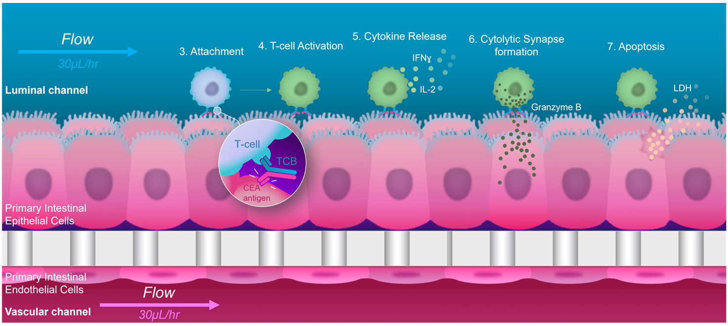
Figure 1. Graphical representation of the major steps in target-dependent T cell–bispecific antibodies engagement and immunomodulation, as performed in the Colon Intestine-Chip
Background
Cancer immunotherapies are treatments that promise delivering durable treatment by harnessing the cytotoxic potential of the immune system against tumor cells (Yang, 2015; Gong et al., 2018; Waldman et al., 2020). Although impressive improvement in long-term survival has been reported (Hodi et al., 2010; Schadendorf et al., 2015; Wolchok et al., 2017), systemic immunomodulation mediated by these drugs often elicits immune-related adverse events, limiting their broad clinical application in battling cancer (Naidoo et al., 2015; Champiat et al., 2017; Kennedy and Salama, 2020).
T cell–engaging bispecific antibodies (TCBs) are a novel class of cancer immunotherapeutic agents that have the potential to improve on the clinical efficacy and safety of traditional immunotherapy (Clynes and Desjarlais, 2019; Labrijn et al., 2019). TCBs exert their anti-tumor activity by simultaneously binding to a cancer surface antigen and to the CD3 T-cell receptor, thereby both activating the T cell and physically crosslinking it to target cells (Bacac et al., 2016). This synthetic immunity approach is particularly favorable for targeting less immunogenic, neo-antigen-lacking tumors, as T cells can be recruited and activated independently of their T-cell receptor specificity. This strictly tumor–targeted immunomodulation is also expected to reduce the systemic inflammatory toxicities associated with traditional immunotherapies (Milling et al., 2017). The therapeutic potential of TCBs is exemplified by the large number of molecules targeting solid and blood tumors, which are currently in various stages of clinical evaluation (Ishiguro et al., 2017; Goebeler and Bargou, 2020).
Although TCBs hold promise for a safer therapeutic option, they are not risk-free. The antigens targeted are rarely exclusive to the tumor, but are also often expressed, albeit at lower levels, in normal tissues, rendering TCBs subject to on-target, off-tumor safety liabilities. This is particularly true for epithelial tumor antigens, as they are frequently targeted in solid tumor indications. For example, a bispecific T-cell engager (BiTE) targeted to the epidermal growth factor receptor (EGFR) produced severe liver and kidney toxicities in non-human primates, in line with EGFR expression in these organs, and led to the termination of the animals (Lutterbuese et al., 2010; Klinger et al., 2016). Clinical adverse events were reported in a recent Phase I study evaluating an epithelial cell adhesion molecule (EpCAM)–targeted BiTE as a therapy for a variety of epithelial carcinomas. Consistent with the expression of EpCAM in the gastrointestinal tract, the molecule triggered severe diarrhea and ultimately prevented escalation to efficacious doses and the identification of a therapeutic window (Kebenko et al., 2018; Trabolsi et al., 2019). Reliable human TCB safety evaluation at the preclinical stage is therefore of vital importance to ensure that well-tolerated and efficacious therapeutics reach patients.
Traditional animal-based preclinical models are often ill-suited for predicting some cancer immunotherapy-mediated adverse events in humans, in part because of the fundamental differences in the immunological responses between the species (Bjornson-Hooper et al., 2019). In the EpCAM example mentioned above, the severity of the diarrhea elicited by the treatment was not predicted by preclinical studies in mice (Brischwein et al., 2006). Moreover, an increasing number of TCBs target human-specific antigens that lack expression in animals, rendering preclinical animal studies uninformative for safety and efficacy assessment (Bacac et al., 2016). Indeed, the development of preclinical models that better translate to human immunity is regarded as one of the top current challenges of cancer immunotherapy (Hegde and Chen, 2020).
While human-relevant cell-based models of tissues and organs promise to bridge this gap, conventional in vitro two-dimensional models fail to provide the complexity required to model the biological mechanisms of immunotherapeutic effects. Furthermore, their reductive microenvironment, devoid of essential cellular, biochemical, and biophysical factors found in the native organ, precludes the expression of TCB targets at physiologically relevant levels and patterns, crucial for capturing TCB pharmacology and safety liabilities.
Organ-on-Chip models aim to overcome these limitations by combining micro-engineering with cultured primary human cells to recreate the complex multifactorial microenvironment and functions of native tissues and organs (Huh et al., 2010). The tissue microenvironment in vivo provides the external signals that help driving cellular differentiation toward mature phenotypes. The key functional aspects of the Organs-on-Chip model regarding tissue-level physiology, such as epithelial and microvascular tissue–tissue interfaces and physiologically relevant mechanical forces, have been shown to capture in vivo relevant phenotypes more accurately (Gayer and Basson, 2009; Kasendra et al., 2018, 2020). The enhanced tissue maturation promoted by Organs-on-Chip could help ensure organ-specific expression of TCB targets, while the modularity of these devices and the possibility for controlled circulation of molecules and immune cells could better capture the functional interactions between TCBs, immune cells, and target-expressing cells that occur in patients. Motivated by these advantages, we set out to evaluate Alveolus Lung- and Colon Intestine-Chip as platforms for the assessment of on-target, off-tumor TCB safety risks in human organs, using a panel of targeting and non-targeting molecules, and leveraging in vivo target expression and toxicity data (Figure 1). We found that these systems could reproduce and predict target-dependent TCB safety liabilities, showing sensitivity to key determinants thereof, such as target expression and antibody affinity (Kerns et al., 2021).
Briefly, the protocol can be outlined broadly as a four-step process. In the first step, Organ-Chips are washed and activated to facilitate the covalent attachment of extracellular matrix proteins (ECM) to the surface of the chip. Appropriate deposition of ECM to the surface is critical to enable productive and physiological downstream cellular attachment. In the second step, cells are harvested from various primary stocks (e.g., frozen vials, organoids, or tissue culture flasks) for seeding onto the prepared chip surfaces. Key considerations in the seeding process are the density of cells and the incubation time needed for cells to adhere to the coated chip surface. After the attachment period, the chips are then connected to the pod reservoir system, which provides media and interface with the Zoë unit, necessary to establish media flow throughout the duration of the experiment. In the third step, the connected chip/pod unit is equilibrated with the Zoë to support continuous flow for the entire experimental period. This period includes an equilibration and maturation window that allows for the seeded epithelium and endothelial layers to mature and develop, according to standard biomarker assessments experimental interrogation. A critical step during this period is the introduction of microenvironmental cues, such as stretch motions or an air–liquid interface, which are necessary for tissue-specific differentiation and maturation. Once the Organ-Chips have achieved the appropriate characteristics for tissue maturation (e.g., barrier function and morphology), the experimental phase of the protocol begins. In this stage, chips are dosed with immune cell populations preincubated with test article solutions and endpoints are collected according to the desired biomarkers panel and experimental timepoints. At the terminal timepoint, the final endpoint specimens are collected, including the harvesting of tissues, and the pod reservoir units are discarded. Chips intended for downstream imaging or other applications can be stored in sterile solutions of balanced salt solutions at 4 °C. The expected result of the above protocol is an assessment of the dose- and time-dependent levels of TCB-mediated T cell activation and killing of the respective alveolar lung or colonic epithelial tissues.
Materials and Reagents
Organ-Chip materials
Emulate Basic Research kit 12 pack (Emulate, catalog number: BRK-WER-12). Kit components: Chip-S1® stretchable chips, Pod® portable modules, ER-1® /ER-2® chip activation reagents, Steriflip® filter. Storage: ER-1® and ER-2® reagents: 2–8 °C; other kit components: ambient temperature (15–25 °C)
Pod imaging adapter kit (Emulate, catalog number: POD-IMG)
Fixed chip imaging adaptor kit (Emulate, catalog number CHIP-IMG)
Emulate colon intestine Bio Kit 12-pack (Emulate, catalog number: BIO-CH1-12). Kit components: Chip-S1® stretchable chips, Pod® portable modules, ER-1® /ER-2® chip activation reagents, Steriflip® Filter. Qualified, biopsy-derived human colonic organoids and primary colonic microvascular colonic endothelial cells (HIMEC). Storage: ER-1® and ER-2® reagents: 2–8 °C; Cells: store in liquid nitrogen; other kit components: ambient temperature (15–25 °C)
Cells and Reagents
Note: Please refer to the Notes section below for more information regarding the specification of the carcinoembryonic antigen (CEA) and folate receptor 1 (FLOR1) targeting reagents below.
Steriflip filters (EMD Millipore, catalog number: SE1M003M00)
T-25 flasks
T-75 flasks
T-150 flasks
15 mL conical tubes
50 mL conical tubes
96-well V-bottom plates
24-well plates
15 mL conical tubes, Protein LoBind® tubes (Eppendorf, catalog number: 0030122216)
50 mL conical tubes, Protein LoBind® tubes (Eppendorf, catalog number: 0030122240)
1.5 mL Eppendorf tubes, Protein LoBind® (Eppendorf, catalog number: 022431081)
1.5 mL Eppendorf tubes
P200 pipette tips with filter (Labcon, catalog number: 1179-965-008-9, or equivalent)
P1000 pipette tips with filter (Labcon, catalog number: 1177-965-008-9, or equivalent)
Square cell culture dish (VWR, catalog number: 82051-068)
Trypan blue (Sigma, catalog number: 93595)
Hemocytometer (SKC Inc., catalog number: DHCN015)
Human primary alveolar epithelial cells (HPAEC):
Human pulmonary alveolar epithelial cells (Accegen, catalog number: ABC-TC3770), or
Human primary alveolar epithelial cells (CellBiologics, catalog number: H-6053)
Human lung microvascular endothelial cells (HMVEC-L) (Lonza, catalog number: CC-2527)
SABM basal medium (Lonza, catalog number: CC-3119), store at 4 °C
SAGM SingleQuots supplement pack (Lonza, catalog number: CC-4124), store at -20 °C
Fetal bovine serum (FBS) (Sigma, catalog number: F4135 or F8317), store at -20 °C
Bovine serum albumin (BSA) (Sigma, catalog number: A9576), store at 4 °C
Dimethyl sulfoxide (DMSO) (Sigma, catalog number: D2650), store at room temperature until expiration
Dexamethasone (Sigma, catalog number: D4902), store at 2-8 °C
Keratinocyte growth factor (KGF) (Thermo Fisher, catalog number: PHG0094)
8-Bromoadenosine 3′,5′-cyclic monophosphate sodium salt (cAMP) (Sigma, catalog number: B7880)
Isobutyl methylxanthine (IBMX) (Sigma, catalog number: I7018)
EBM-2 basal medium (Lonza, catalog number: CC-3156), store at 4 °C
EGM-2MV SingleQuots supplement pack (Lonza, catalog number: CC-4147), store at -20 °C
Medium 199 (Thermo Fisher, catalog number: 11043023), store at 4 °C
Epidermal growth factor (EGF) (PromoCell, catalog number: C-60170)
Basic human fibroblast growth factor (FGF) (PromoCell, catalog number: C-60243)
Vascular endothelial growth factor (VEGF) (PromoCell, catalog number: C-64420)
Hydrocortisone (Sigma, catalog number: H0135)
Heparin (Sigma, catalog number: H3149)
Gelatin solution (ATCC, catalog number: PCS-999-027)
Accutase (Stemcell Technologies, catalog number: 07920)
Penicillin-Streptomycin (Pen-Strep) (Sigma, catalog number: P4333), store at -20 °C
Easy 50 EasySep magnet (Stemcell Technologies, catalog number: 18002)
Direct human PBMC isolation kit (Stemcell Technologies, catalog number: 19654), store at 4 °C
Dulbecco’s PBS (DPBS) without Ca2+ , Mg2+ (Gibco, catalog number: 21-031-CV), store at room temperature
Placental collagen type IV (Sigma, catalog number: C5533), store at -20 °C
Human plasma fibronectin (Corning, catalog number: 356008), store at 2–8 °C (lyophilized) for three months or at -20 °C for two weeks
Laminin (Sigma, catalog number: 6274)
L-Glutamax (Thermo Fisher, catalog number: 35050-061), store at 4 °C
Advanced DMEM/F12 (Thermo Fisher, catalog number: 12634028), store at 4 °C
IntestiCult (Stem Cell Technologies, catalog number: 06010), store media components at -20 °C
Y-27632 (Stem Cell Technologies, catalog number: 72304), store at -20 °C desiccated, protect from light
CHIR99021 (Reprocell, catalog number: 04-0004-10), store powder at 4 °C protected from light, store aliquots at -20 °C
Primocin (InvivoGen, catalog number: ANT-PM-1), store at -20 °C
Attachment factor (Cell Systems, catalog number: 4Z0-210), store at 4 °C
Matrigel-growth factor reduced (Corning, catalog number: 356231), store at -20 °C
TrypLE Express (Gibco, catalog number: 12604013)
Cell recovery solution (Corning, catalog number: 354253)
Mini cell scraper (Biotinium, catalog number: 22003)
RPMI-1640 (Gibco, catalog number: 11875093), store at 4 °C
Dextran Cascade Blue 3000 MW (Invitrogen, catalog number: D7132)
CMFDA cell tracker green (Thermo Fisher, catalog number: C7025), store in freezer -5 °C to -30 °C, protect from light
NucView 405 (Biotium, catalog number: 10407)
4% paraformaldehyde in aqueous solution (PFA) (VWR, catalog number: 102091-904), store at room temperature
1× PBS with 0.05% sodium azide (Teknova, catalog number: P0202)
BD perm/wash buffer (BD BioSciences, catalog number: 554723, store at room temperature
Cell staining buffer (BioLegend, catalog number: 420201), store at 4 °C
Anti-Human FOLR1 (R&D Systems, catalog number: MAB5646)
Mouse IgG1 isotype control (R&D Systems, catalog number: MAB002) QIFIKIT® (Agilent Technologies, Inc., catalog number: K007811-8), store at 4 °C
Anti-human CD3 HIT3a Alexa Flour 700 (BioLegend, catalog number: 300324), store at 4 °C
Anti-human CD4 OKT4 BV785 (BioLegend, catalog number: 317442), store at 4 °C
Anti-human CD69 FN50 BV650 (BioLegend, catalog number: 310934), store at 4 °C
Anti-human CD3 HIT3a APC-Cy7 (BioLegend, catalog number: 300318), store at 4 °C
Anti-human CD8 SK1 PE/Dazzle-594 (BioLegend, catalog number: 344744), store at 4 °C
Anti-human CD25 BC96 PerCP-Cy5.5 (BioLegend, catalog number: 302625), store at 4 °C
Anti-human CD69 FN50 APC (BioLegend, catalog number: 310910), store at 4 °C
NucBlue fixed cell ready probes reagent (DAPI) (ThermoFisher, catalog number: R37606)
Mouse anti-human FOLR1 (L.S Bio, catalog number: LS-C125620)
Rabbit polyclonal anti-E-cadherin (Abcam, catalog number: ab15148)
7.5% BSA (Thermo Fisher, catalog number: 15260037)
Normal donkey serum (Abcam, catalog number: ab7475)
Anti-CEACAM5 antibody (CI-P83-1) (Santa Cruz Biotechnology, catalog number: sc-23928)
Purified mouse IgG2a kappa isotype Ctrl (MOPC-173) (BioLegend, catalog number: 400202)
Recombinant rabbit anti-CEA (Abcam, catalog number: ab133633), store at 4 °C short term (1–2 weeks), upon delivery aliquot and store at -20 °C
Monoclonal rat anti-CD45 (Invitrogen, catalog number: MA5-17687), store at 4 °C short term (1–2 weeks), upon delivery aliquot and store at -20 °C
DRAQ5TM fluorescent probe solution (5 mM) (Thermo Fisher, catalog number: 62251), store at 4 °C, protect from light
DyLightTM 405 AffiniPure donkey anti-rat IgG (H+L) (Jackson ImmunoResearch, catalog number: 712-475-153), store at 4 °C short term (1–2 weeks). Upon delivery, aliquot and store at -20 °C, protect from light
Donkey anti-rabbit IgG (H+L) secondary antibody, Alexa FluorTM 555 (Thermo Fisher, catalog number: A-31572), store at 4 °C, protect from light
Goat anti-human IgG (H+L) secondary antibody, Alexa FluorTM 555 (Thermo Fisher, catalog number: A-21433), store at 4 °C, protect from light
CellEventTM Caspase-3/7 green detection reagent (Thermo Fisher, catalog number: C10423), store at ≤ -20 °C protected from light
LIVE/DEADTM fixable yellow dead cell stain kit (Thermo Fisher, catalog number: L34959), store at ≤ -20 °C protected from light
Customized ProcartaPlex multiplex immunoassay (Invitrogen, catalog number: PPX-12-MXNKRV6). Panel including human targets: IFNγ, TNFα, Granzyme-B, IL-2, IL-4, and IL-8
ER-1 (Emulate, catalog number: BRK-WER-12)
ER-2 (Emulate, catalog number: BRK-WER-12)
PBMC culture media (see Recipes)
ER-1 solution (see Recipes)
Alveolus ECM stock solutions (see Recipes)
Alveolus ECM working solutions (see Recipes)
HPAEC culture medium or complete SAGM culture medium (see Recipes)
HPAEC maintenance media (see Recipes)
HMVEC-L culture medium or complete EGM-2MV culture medium (see Recipes)
ALI culture medium (see Recipes)
CMFDA cell tracker green (see Recipes)
PCMC dosing media (see Recipes)
FACs buffer (see Recipes)
1% PFA solution (see Recipes)
Y-27632 (ROCK inhibitor) (see Recipes)
CHIR99021 (GSK-3 inhibitor) (see Recipes)
Matrigel-growth factor reduced (see Recipes)
Collagen IV (see Recipes)
Fibronectin (see Recipes)
3 KDa Dextran Cascade Blue (see Recipes)
Colon ECM stock solutions (see Recipes)
Colon ECM working solutions (see Recipes)
Colonoid thawing media (see Recipes)
IntestiCult expansion media (see Recipes)
IntestiCult maintenance media (see Recipes)
Colonoid dissociation solution (see Recipes)
Cell counting solution (see Recipes)
HIMEC culture medium (see Recipes)
Live/dead fixable yellow dead stain (see Recipes)
PBMC dosing media (see Recipes)
Equipment
Zoë culture module (Emulate, catalog number: ZOE-CM2)
Orb hub (Emulate, catalog number: Orb-HM1)
Centrifuge (Sorvall, Thermo Fisher, model number: 75-200-395)
UV light box (Emulate, Inc.)
Inverted phase contrast microscope with 10× and 20× objectives (Echo Revolve Microscopes)
Inverted fluorescent microscope with 10× and 20× objectives (Echo Revolve and Olympus Microscopes)
Biosafety cabinet
BD FACSCelestaTM flow cytometer (BD Biosciences, model: 660344)
ProcartaPlex multiplex immunoassays (Invitrogen PPX-12-MXNKRV6)
BioPlex-200 (Bio-Rad)
Software
ICY software (BioImage Analysis Lab, Institut Pasteur, https://icy.bioimageanalysis.org/)
FACSDiva (BD Bioscience, https://www.bdbiosciences.com/en-us/products/software/instrument-software/bd-facsdiva-software)
FIJI (Schindelin et al., 2012) ( https://imagej.net/software/fiji/)
Bio-Formats plugin for ImageJ (The Open Microscopy Environment, https://www.openmicroscopy.org/bio-formats/downloads/)
Zen (blue edition) (Carl Zeiss AG, https://www.zeiss.com/microscopy/us/products/microscope-software/zen.html)
FlowJo (FlowJo LLC, https://www.flowjo.com/)
GraphPad Prism (GraphPad, https://www.graphpad.com/)
BioPlex Manager (Bio-Rad, https://www.bio-rad.com/en-us/product/bio-plex-manager-software-standard-edition?ID=5846e84e-03a7-4599-a8ae-7ba5dd2c7684)
Part I: Culture of the Alveolar Lung-Chip for TCB-mediated T cell activation and killing
Procedure
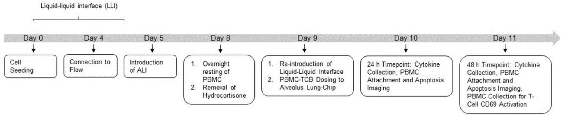
Figure 2. Experimental timeline for the culture of the human Alveolar Lung-Chip
Isolation and cryopreservation of peripheral blood mononuclear cells (PBMCs)
Note: Please refer to the Notes section below for a further discussion on why PBMCs are the recommended cell source used for the TCB-mediated T cell activation and killing assessment. Refer to Alveolar Lung-Chip experimental timeline (Figure 2).
Prepare PBMC culture media (see Recipes).
Isolate PBMCs from fresh human buffy coat using the direct human PBMC isolation kit following manufacturer’s instructions.
Approximately 10 million viable PBMCs per chip will be needed to complete the T cell activation and killing assessment.
Cryo-preserve PBMC in FBS supplemented with 10% DMSO.
Thawing human primary alveolar epithelial cells (HPAEC) (Day -1)
Heat 50 mL of complete SAGM culture medium to 37 °C.
Coat a T-25 flask with gelatin solution by adding 3 mL of 0.1% gelatin solution.
Incubate the flask at 37 °C and 5% CO2 for 5–10 min.
Thaw the vial(s) of cells by immersing in a 37 °C water bath.
Immediately transfer the contents of the vial into 3 mL of warm complete SAGM in a sterile 15 mL conical tube.
Rinse the vial with 1 mL of complete SAGM and collect in the 15 mL tube.
Bring the volume to 15 mL with complete SAGM culture medium.
Centrifuge at 200 × g for 5 min at room temperature.
Aspirate and discard supernatant, leaving approximately 100 µL of medium covering the cell pellet.
Resuspend cells in 7 mL of complete SAGM culture medium.
Add the HPAEC suspension to the T-25 flask.
Incubate overnight at 37 °C and 5% CO2 .
Exchange with freshly warm complete SAGM once a day until use for seeding in the chip.
Thawing human lung microvascular endothelial cells, HMVEC-L (Day -1)
Heat 50 mL of complete EGM-2MV culture medium to 37 °C.
Thaw the vial(s) of cells by immersing in a 37 °C water bath.
Immediately transfer the contents of the vial into 3 mL of warm complete EGM2-MV culture medium in a sterile 15 mL conical tube.
Rinse the vial with 1 mL of complete EGM-2MV culture medium and collect in the 15 mL tube.
Bring the volume to 15 mL with complete EGM2-MV culture medium.
Add the HMVEC-L suspension to the T75 flask.
Incubate for 6 h (until 60%–80% cells have adhered) at 37 °C and 5% CO2 .
Aspirate the culture medium and add complete EGM-2MV culture medium to remove traces of DMSO.
Incubate overnight at 37 °C and 5% CO2 .
Exchange with freshly warm complete EGM-2MV culture medium every other day until use for seeding in the chip.
Chip activation and preparation (Day -1)
ReviewVideo 1: Chip activation.
 Video 1. Chip activation
Open the chip cradle sterile packaging and place the cradle into the 120 mm square dish, making sure the chip cradle is oriented properly with the corners facing up.
Open the chip packaging carefully and place the first chip into the chip cradle by sliding the back of the carrier under the tabs on the cradle.
Prepare the ER-1 solution (see Recipes)
Note: All solutions in these steps are used at room temperature.
Using a P200 pipette and a sterile 200 μL filtered pipette tip, take up 200 μL of ER-1 solution.
Note: 200 μL of ER-1 solution will fill approximately three chips. Also, filtered tips help to maintain sterile conditions during chip preparation steps.
Carefully introduce approximately 20 μL of ER-1 solution through the bottom channel inlet, pipetting until the solution begins to exit the bottom channel outlet.
Without releasing the pipetting plunger, take the pipette out from the bottom channel inlet and move the pipette containing the remaining ER-1 solution to the top channel inlet.
Introduce approximately 50 μL of ER-1 solution to the top channel inlet, pipetting until the solution begins to exit the top channel outlet.
Remove all excess ER-1 solution from the surface of the chip by gentle aspiration. Be sure only to remove ER-1 solution from the chip surface—do not aspirate ER-1 from the channels.
Repeat steps D1–D5 for each chip.
Inspect the channels for bubbles prior to UV activation. If bubbles are present, dislodge by washing the channel with ER-1 solution until all bubbles have been removed. If bubbles persist, it may be helpful to aspirate the channel dry and slowly reintroduce ER-1 solution.
Bring the ER-1-coated chips to the UV light box.
Before placing the chips into the UV light box, make sure to remove the cover from the 120 mm square dish.
Note: If the cover is not removed prior to placing the dish in the UV light box, the chips will not activate properly, which could result in poor cell attachment.
Set the switch at the back of the UV light box to the “Constant” setting. Turn on the “Power” and press the “On” button to begin UV activation.
Allow the chips to activate under UV light for 10 min.
After UV treatment, bring the chips back to the biosafety cabinet (BSC).
Aspirate activated ER-1 from all channels and refill channels with fresh ER-1 as before.
Bring the chips back to the UV light box and activate under UV light for an additional 5 min.
While the chips are being treated, prepare the top and bottom channel alveolus ECM working solution (see Recipes).
After UV treatment, bring chips back to the BSC.
Note: The light may be on in the BSC from this point forward.
Fully aspirate the ER-1 solution from both channels for approximately 1–2 s.
Wash each channel with 200 μL of ER-2 solution.
Fully aspirate the ER-2 from the channels for approximately 1–2 s.
Wash each channel with 200 μL of sterile DPBS.
Leave DPBS inside the channels.
Chip coating with ECM (Day -1)
Review Video 2. Activation and coating of chips with extracellular matrix proteins.
Video 2. Activation and coating of chips with extracellular matrix proteinsFully aspirate cold DPBS from both channels.
Using a P200 pipette, take up 200 μL of alveolus or colon ECM working solution.
Carefully introduce alveolus or colon ECM working solution through the bottom channel inlet until a small ECM droplet forms on the outlet.
Without releasing the pipetting plunger, take the pipette out from the bottom channel inlet and move to the next chip, repeating steps E2–E4 for each chip.
Using a P200 pipette, take up 200 μL alveolus or colon ECM working solution.
Carefully introduce alveolus or colon ECM working solution through the top channel inlet until a small ECM droplet forms on the outlet.
Without releasing the pipetting plunger, take the pipette out from the top channel inlet and move to the next chip, repeating steps E5–E7 for each chip.
Inspect channels to ensure that no bubbles are present. If bubbles are present, dislodge by washing the channel with the respective top or bottom channel ECM solutions until all bubbles have been removed.
To prevent evaporation during incubation, fill central reservoir of the chip cradle with 0.75 mL of DPBS (Figure 3), place the lid onto a 120 mm square dish, and incubate overnight at 37 °C and 5% CO2 .
Note for Alveolar Lung-Chip: If desired, HPAEC can be seeded the same day as chip activation and ECM coating, though incubation overnight is preferred for best result. Chips can be ready for same-day seeding of HPAEC 4 h after adding the ECM solutions and incubating chips at 37 °C and 5% CO2 . If chips will be stored longer than overnight before seeding, store the chips at 4 °C for up to two days.
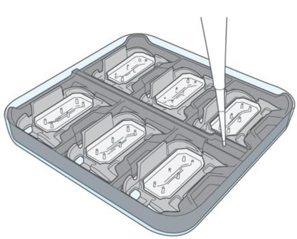
Figure 3. Fill central reservoir of chip cradle
Prepare chips for seeding (Day 0)
Gently wash each channel of the chip with 200 μL of warm complete SAGM culture medium.
Aspirate the medium outflow at the surface of the chips, leaving the medium in the channels.
Repeat the wash with an additional 200 μL of complete SAGM culture medium per channel, leaving the excess medium outflow covering the inlet and outlet ports.
Cover the 120 mm dish and place the chips in the incubator until the cells are ready for seeding.
Harvest of HPAECs (Day 0)
Bring the T-25 flask containing HPAECs from the incubator into the BSC.
Aspirate culture media from a T-25 flask of confluent HPAECs.
Add 5 mL of DPBS preincubated to 37 °C to wash the culture surface and aspirate the DPBS wash.
Add 3 mL of TrypLE Express to the flask and incubate for 10–15 min at 37 °C and 5% CO2 .
Tap the side of the flask gently and inspect the culture under the microscope to assess complete detachment of cells from the flask surface.
Add 7 mL of warm complete SAGM culture medium to the flask and pipette gently to mix, while collecting all cells from the flask surface.
Transfer the contents of the flask into a sterile 15 mL conical tube.
Centrifuge HPAECs at 200 × g for 5 min at room temperature.
Carefully aspirate the supernatant, leaving approximately 100 μL of medium above the cell pellet.
Note: The cell pellet will be very small. Aspirate carefully.Loosen the cell pellet by flicking the tube gently.
Using a P1000 pipette, gently resuspend the cells by adding 500 μL of warm complete SAGM culture medium.
Pipette gently to create a homogeneous mixture and transfer 10 μL of the cell suspension to the cell counting solution of 80 μL SAGM culture medium + 10 μL trypan blue, making a 1:10 dilution.
Mix the counting solution thoroughly and count cells using a manual hemocytometer.
Count both viable and non-viable cells.
Calculate percent viability of the cell solution.
The expected viability of the HPAECs should be greater than 80%.
Calculate viable cell concentration.
Calculate viable cell yield, or total number of viable cells.
Dilute with warm complete SAGM culture medium to the required final cell density of 1 × 10⁶ cells/mL viable HPAECs.
Seed HPAECs to top channel (Day 0)
Bring the 120 mm dish containing the prepared chips to the BSC.
Avoiding contact with the inlet and outlet ports, carefully aspirate excess medium droplets from the surface of one chip.
Very gently agitate cell suspension before seeding each chip to ensure a homogeneous cell suspension.
Quickly and steadily pipette 35–50 μL of the cell suspension (at 1 × 10⁶ cells/mL) into the top channel inlet port, while aspirating the outflow fluid from the chip surface. Avoid direct contact with the outlet port.
Cover the dish and transfer to the microscope to check the seeding density within the chip.
Note: At this stage, optimal seeding density should form an even layer with cell-to-cell spacing of approximately half the radius of a single cell.
If seeding density is not optimal, return the chips to the BSC and wash the channel with 200 μL of fresh medium twice. Adjust cell density accordingly and repeat steps H3–H5 until the correct density is achieved within the channel.
After confirming the correct cell density, seed cells in the remaining chips.
Note: Minimize the amount of time the cells are outside the incubator by seeding no more than six chips at a time and immediately placing them in the incubator at 37 °C after seeding each batch.
Place the chips with DPBS in the central reservoir of the chip cradle (Figure 3) at 37 °C for at least 2 h or until cells have attached (Figure 4).
Note: Correct seeding density is essential for success of Alveolar-Lung Chips.
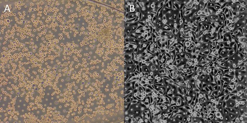
Figure 4. Representative brightfield images of epithelial (HPAEC) cell seeding density. (A) Optimal seeding density immediately after seeding and (B) 2 h post-seeding at 1 × 10⁶ per mL.
Wash chips (Days 1 and 2)
Note: A gentle wash is performed 2 h post-seeding once the cells have attached, to ensure that nutrients are replenished and the channels do not dry out. If cells are not attached, incubate overnight and then wash.
Gently pipette 200 μL of warm complete SAGM culture medium to the top and bottom channels of each chip to wash. Aspirate the outflow, leaving media in the channel.
Place additional droplets of media to fully cover all inlet and outlet ports to prevent evaporation from the ports (Figure 5).
Incubate chips overnight at 37 °C.
Repeat steps I2 and I3 once daily with HPAEC maintenance media (see Recipes) for the next two days.
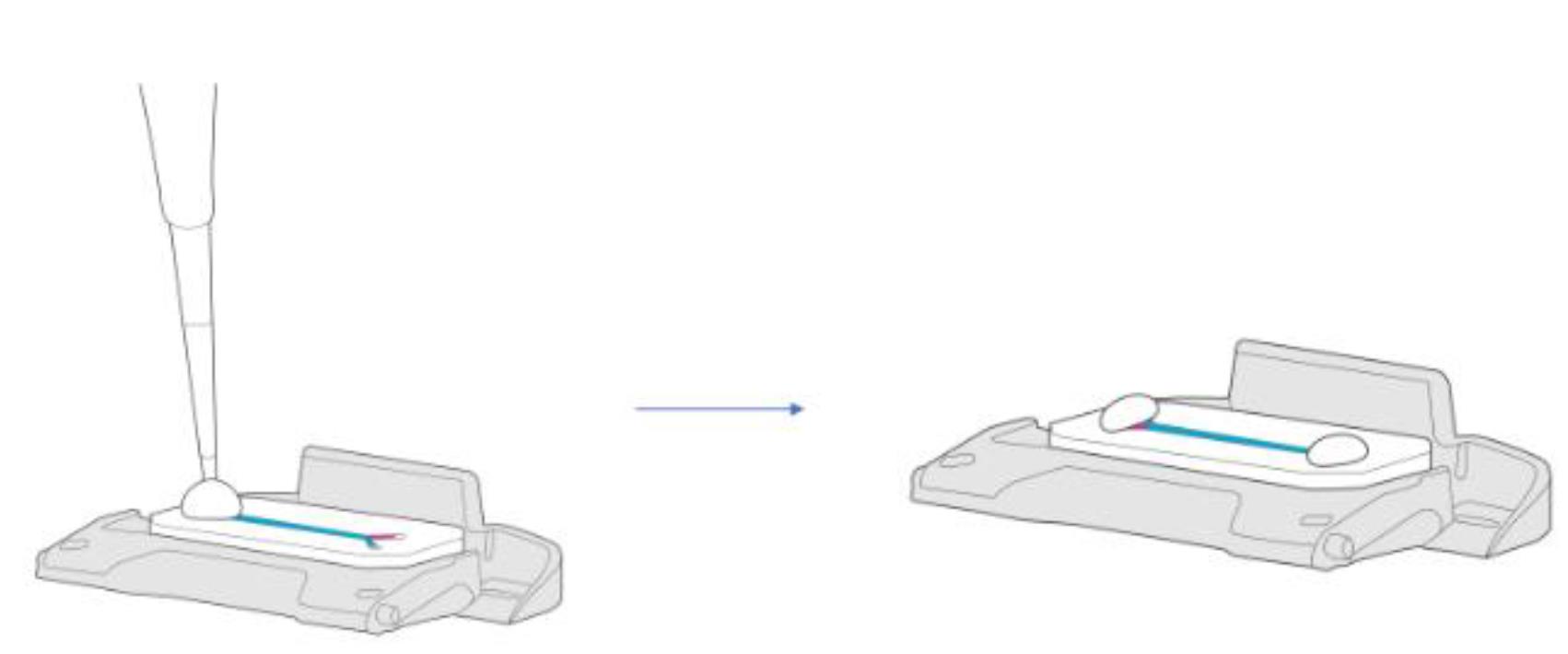
Figure 5. Chip with medium drops covering the inlet and outlet ports
Prepare chips (Day 3)
Gently pipette 200 μL of warm HPAEC maintenance medium to the top channel of each chip to wash. Aspirate the outflow, leaving medium in the channel.
Pipette 200 μL of warm complete EGM-2MV culture medium to the bottom channel of each chip. Aspirate the outflow, leaving medium in the channel.
Return chips to the incubator until HMVEC-Ls are ready for seeding.
Harvest HMVEC-Ls (Day 3)
Aspirate culture medium and add 15 mL of 1× DPBS to wash the culture surface. Aspirate the DPBS wash.
Add 5 mL of TrypLE Express to the flask. Incubate for 5–10 min at 37 °C.
Tap the side of the flask gently and inspect the culture under the microscope to assess complete detachment of cells from the culture surface.
Add 7 mL of warm complete EGM-2MV culture medium to the flask and pipette gently to mix, while collecting all cells from the culture surface.
Transfer the contents of the flask (12 mL) into a sterile 15 mL conical tube.
Centrifuge HMVEC-Ls at 200 × g for 5 min at room temperature.
Carefully aspirate the supernatant, leaving approximately 50–100 μL of medium above the cell pellet.
Note: The cell pellet will be small. Aspirate carefully.
Loosen the cell pellet by flicking the tube gently.
Using a P1000 pipette, gently resuspend the cells by adding 500 μL of complete EGM-2MV culture medium.
Pipette gently to create a homogeneous mixture and transfer 10 μL of the cell suspension to the cell counting solution of 80 µL SAGM and 10 µL trypan blue (this will make a 1:10 dilution).
Mix the counting solution thoroughly and count cells using a manual hemocytometer.
Count both viable and non-viable cells.
Calculate percent viability of the cell solution.
The expected viability of the HMVEC-Ls should be greater than 80%.
Calculate viable cell concentration.
Calculate viable cell yield.
Dilute to 5 × 10⁶ cells/mL viable HMVEC-Ls in complete EGM-2MV culture medium.
Seed HMVEC-Ls to bottom channel (Day 3)
Bring the 120 mm dish containing the prepared chips to the BSC.
Avoiding contact with the ports, aspirate DPBS from cradle reservoir and carefully aspirate excess medium droplets from the surface of one chip.
Gently agitate cell suspension before seeding each chip to ensure a homogeneous cell suspension.
Seed 15–20 μL of the endothelial cell suspension into the bottom channel of one chip first, while aspirating the outflow.
Cover the dish and transfer to the microscope to check the seeding density within the chip (see Figure 6 for reference).
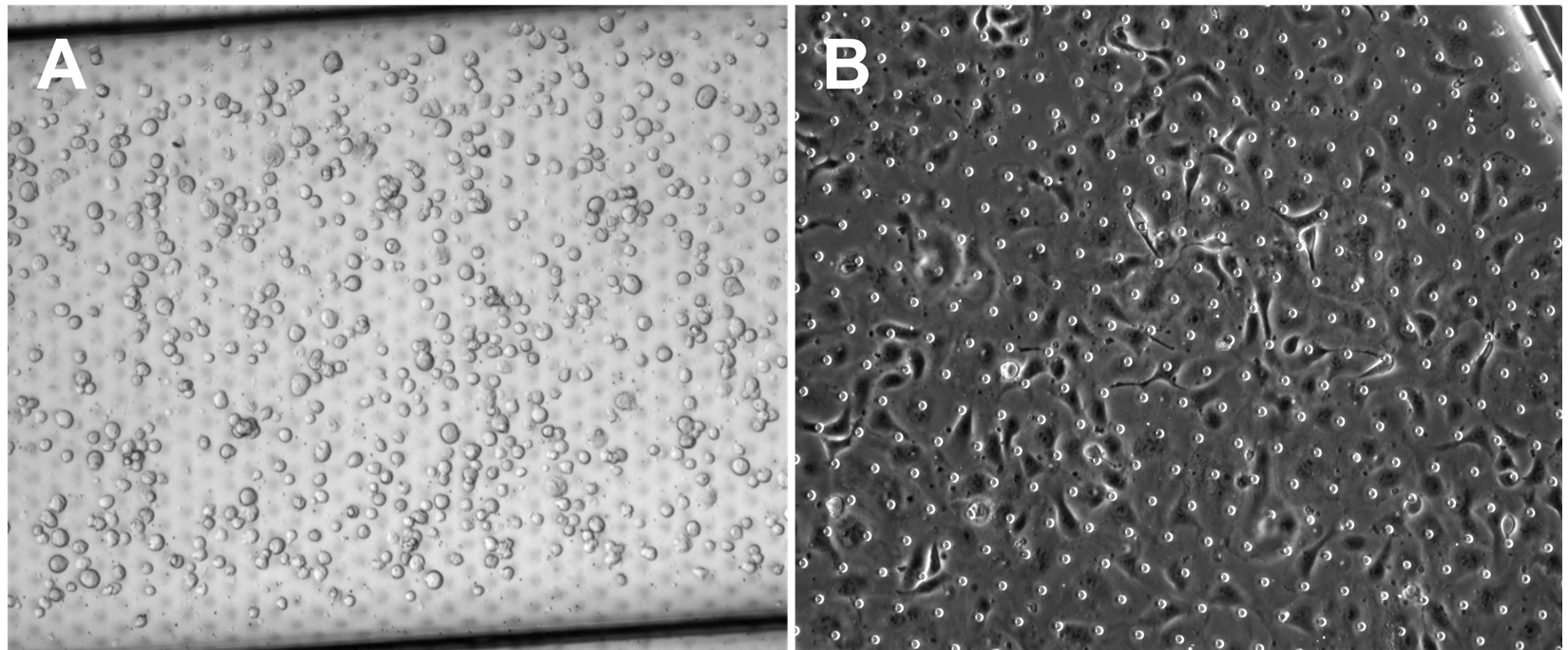
Figure 6. Endothelial (HMVEC-L) optimum cell seeding density. (A) Optimal seeding density under brightfield microscopy, immediately after seeding into the bottom channel at 5 × 10⁶ per mL. (B) HMVEC-Ls attached on chip 1.5 h post-seeding.If seeding density is not optimal, return the chip to the BSC and wash the channel twice with 200 μL of fresh endothelial cell culture medium. Do not aspirate the medium from the channel prior to washing. Adjust the volume of the cell suspension as needed to obtain correct seeding density and repeat steps L3–L5 until the correct density is achieved within the channel.
After confirming the correct cell density, seed the remaining chips in the chip cradle.
Note: Minimize the amount of time the cells are outside the incubator by seeding no more than six chips at a time and immediately placing them in the incubator at 37 °C after seeding.
Once all six chips have been seeded place each in the cradle, cover the dish and carefully invert it (Figure 7).
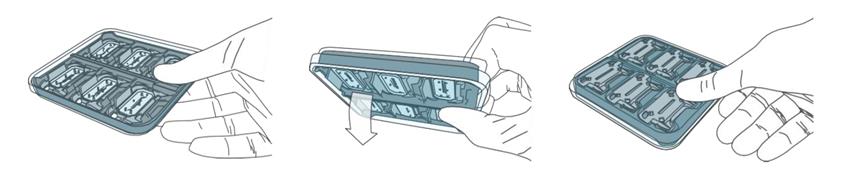
Figure 7. Inverting chips during endothelial attachmentTo prevent evaporation during incubation, refill central reservoir with 0.75 mL of DPBS and place cover onto square dish.
Proceed with remaining chips until all have been seeded.
Incubate at 37 °C for 2 h, or until cells in the bottom channel have attached.
Once endothelial cells have attached (approximately 2 h post-seeding), aspirate DPBS from the central reservoir and flip the dish back so the chips are in an upright position in the chip cradle.
Note: It is recommended to always seed any remaining cells into a plate as control for cell quality.
Wash with tips (Day 3)
Once HMVEC-Ls have attached, flip the chips back to an upright position.
Note: Remove the chip cradle, wipe with 70% ethanol to clean, and autoclave for use in next experiment.
A wash with 200 μL of HPAEC maintenance medium for the top channel and complete EGM-2MV culture medium for the bottom channel per chip will provide nutrients to cells. Since there are two different media being used, these must be separated by keeping them in filtered tips instead of drops (Figure 8).
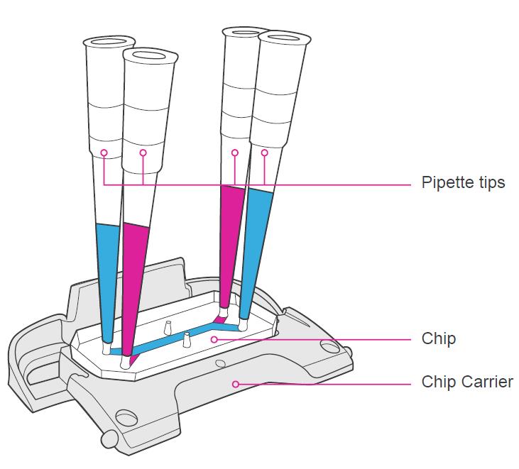
Figure 8. Chip with filtered tips inserted into ports with respective mediaReturn chips with pipette tips inserted in each inlet and outlet port to the incubator overnight.
Maintain cells in static culture in chips until connecting to pods and Zoë the next day.
Note: If desired, chips can be connected at least 2 h post-attachment.
Gas equilibration of media (Day 4)
Note: The media equilibration step is important for the success of Organ-Chip culture. Omission of this step will cause the eventual formation of bubbles in the chip, the pod, or both, which will in turn cause irregular flow and negatively impact cell viability. Minimize the time media is outside of a warmed environment to no more than 10 min, as gas equilibrium can become compromised when media is allowed to cool.
Place at least 3 mL of HPAEC maintenance medium for each chip in a 50 mL conical tube.
Place at least 3 mL of complete EGM-2MV culture medium for each chip in a separate 50 mL conical tube.
Heat both 50 mL conical tubes of media at 37 °C in a water or bead bath for at least 1 h.
Immediately connect the 50 mL tube containing each warmed medium to a Steriflip® unit.
Attach each conical tube containing warmed medium to a Steriflip® unit.
With the unit right-side up (medium in the bottom conical tube), apply vacuum for 10 s.
Invert the Steriflip® -connected tubes and check that the medium begins to pass from the top conical tube to the lower tube.
Note: The vacuum source must operate at least at -70 kPa. At this correct pressure, it should take approximately 2 s for every 10 mL of medium to flow through the filter. If it takes longer, stop and see the troubleshooting protocol, as this indicates the medium is not equilibrated properly.
Leave the filtered medium under vacuum for 5 min.
Remove the vacuum tubing from the Steriflip® units.
Separate the conical tubes containing media from the Steriflip® unit and immediately place them in the incubator with the caps loose.
Media priming of pods (Day 4)
Open the pod package and place the pods into the trays. Orient the pods with the reservoirs toward the back of the tray (Figure 9A).
Pipette 2 mL of pre-equilibrated warm media to each inlet reservoir. In the top channel inlet reservoir add HPAEC maintenance medium; in the bottom channel inlet reservoir add complete EGM-2MV culture medium (Figure 9C).
Pipette 300 μL of pre-equilibrated warm media to each outlet reservoir, directly over each outlet via (Figure 9C).
Bring trays containing pods to the incubator and slide completely into Zoë with the tray handle facing outward.
Run the prime cycle on Zoë.
Use the rotary dial to highlight “Prime” on the display.
Press the rotary dial to select “Prime.”
Rotate the dial clockwise to highlight “Start.”
Press the dial again to select “Start” and begin.
Note: Once “Start” is selected, there will be an audible sound as Zoë engages the pods.
Close the incubator door and allow Zoë to prime the pods; this process takes approximately 1 min.
Note: When the status bar reads “Ready,” the “Prime” cycle is complete.
Remove the tray from Zoë and bring to the BSC.
Verify that the pods were successfully primed (Figure 9B). This is important for success.
Inspect the underside of each pod—look for the presence of small droplets at all four fluidic ports. Droplets will vary in size from a small meniscus to larger droplets; often, droplets on the outlet ports will be larger.
If any pod does not show droplets, rerun the “Prime” cycle on those Pods.
If any media dripped onto the tray (this may occur more often by the outlet ports), clean tray with a wipe sprayed with 70% ethanol.
Once it is confirmed that all pod ports are wet with droplets, put the tray of pods to the side in the BSC.
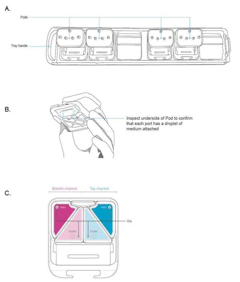
Figure 9. Illustration of chip & pod handling. (A) Illustration of chip tray and pods. (B) Illustration demonstrating pod handling and description of the visual inspection necessary to observe droplet formation after priming step. (C) Schematic representation of the pod reservoirs indicating the respective top and bottom channels and inlet and outlet ports.
Wash chips (Day 4)
Transfer the seeded chips in a 150 mm dish from the incubator to the BSC.
Remove the pipette tips from the chip inlet and outlet ports.
Gently wash the top channel of each chip with warm equilibrated HPAEC maintenance medium to remove any possible bubbles in the channel.
Place small droplets of equilibrated HPAEC maintenance medium on the top of each top channel inlet and outlet port of each chip.
Gently wash the bottom channel of each chip with warm equilibrated complete EGM-2MV culture medium to remove any possible bubbles in the channel.
Place small droplets of equilibrated complete EGM-2MV culture medium on the top of each bottom channel inlet and outlet ports of each chip.
Chips-to-Pods (Day 4)
Holding one chip (while it remains in the chip carrier) with the dominant hand and one pod with the non-dominant hand, slide the chip carrier into the tracks on the underside of the pod until the chip carrier has seated fully.
Place the thumb on the chip carrier tab and gently but firmly depress the tab in and up to engage the tab of the chip carrier with the pod.
Aspirate any excess medium on the chip surface from the pod window.
Place the pod with the connected chip onto the tray.
Repeat steps Q1–Q4 for each pod and chip carrier.
Confirm that there is sufficient media in each pod inlet and outlet reservoirs and that the pod lids are flat and secure.
Pods-to-Zoë (Day 4)
Place trays that are holding pods and chips immediately into Zoë to prevent media from cooling and losing its gas equilibration.
Set top channel flow rate to 0 μL/h and bottom channel flow rate to 30 μL/h.
Run the regulate cycle.
Using the rotary dial, highlight the “Regulate” field.
Press the dial to select “Regulate” and rotate the dial clockwise to “Start.”
Press the dial again to select “Start” and begin the regulate cycle.
Note: Once “Start” is selected, there will be an audible sound as Zoë engages the pods.
At this point the “Activation” button will glow blue.
The regulate cycle lasts 2 h. After the cycle has finished, Zoë will begin flow at the preset Organ-Chip culture conditions. To cancel the regulate cycle (only if needed) on Zoë, select the “Regulate” field with the dial and press the button to select. Rotate the dial counterclockwise to select “Cancel.” Press the dial once more and wait 1 min for the cycle to end, after which the tray can be removed. If canceled, always rerun a complete regulate cycle before proceeding.
Via wash and the regulate cycle (Day 5)
ReviewVideo 3: Pod priming and regulate cycle.
The day after connecting chips and pods to Zoë, which begins the process of Organ-Chip culture, pause the Zoë by pressing the silver “Activation” button located above the tray bays. This stops flow and releases the pods.
Slide the tray out of the bay and transfer to the BSC.
Remove the pod lids. Using a 200 μL pipette, perform a via wash on each pod inlet and outlet reservoir:
Using media within the pod reservoir, pipette 200 μL of media directly over the top of the via to dislodge any bubbles that may be present.
Repeat this wash step for each of the four pod reservoirs.
Replace pod lids and return the trays to Zoë.
Video 3. Pod priming and regulate cycle
Establishing air–liquid interface (ALI) and maintenance (Day 5)
Note: Only establish ALI 12 or more hours after running regulate. Do not rerun regulate cycle once ALI is established.
Pause Zoë by pressing the silver “Activation” button and move pods into the BSC.
Using a complete aspiration technique, aspirate all media from both inlet and outlet reservoirs along all four edges of the reservoir for the top channel for all pods that require culture at ALI. Transfer all trays and pods back into Zoë.
Set top channel flow rate to 1,000 μL/h and bottom channel to 0 μL/h. Start flow and allow to run for 1 min. This step gently pushes any remaining media from the top channel and collects it in the top channel outlet reservoir.
Pause Zoë as previously described and move pods into the BSC. Immediately aspirate all remaining media from top channel outlet reservoir to avoid media backflow from the outlet reservoir into the channel.
Using the microscope, check to confirm that the top channel does not contain medium.
If channels are not completely free of medium, place back in Zoë and run for another 1 min at 1,000 μL/h.
Aspirate all medium from bottom channel inlet and outlet reservoirs, leaving a small liquid layer over the bottom inlet reservoir via. This will prevent introducing unwanted bubbles during flow.
Add 2–4 mL of warm ALI culture medium to the bottom channel inlet reservoirs.
Pipette 1 mL of media in the air channel pod inlet reservoir first, then immediately pipette 1 mL of media in the air channel pod outlet reservoir.
Note: This equal media distribution in the pod reservoirs is required to maintain static pressure in the air channel.
Transfer all trays and pods back to Zoë.
Set top channel to “Air.”
Set bottom channel flow rate to 30 μL/h.
Press the activation button to resume Zoë operation.
Refresh medium in bottom channel inlet reservoir every other day or as needed.
Sampling and media replenishment (Day 6+)
Pause Zoë by pressing the silver “Activation” button.
Remove the trays and place in the BSC.
Visually inspect each chip for bubbles.
Using a microscope, inspect cells in the chips to assess morphology and viability. Capture representative images at 10× or 20× magnification at the following locations (Figure 10):
Inlet junction.
Center of channel.
Outlet junction.
Remove the pod lids and collect effluent medium from pod outlet reservoirs for analysis. Collect effluent from the indicated regions, avoiding disturbing the pod reservoir vias.
Gently aspirate any medium not collected for analysis, ensuring that a thin liquid film still covers the reservoir vias so that no air is introduced into the vias.
Refill the pod media reservoirs with fresh complete ALI medium and perform a via wash: using medium within the pod reservoir, pipette 1 mL of medium directly over the top of the via to dislodge any bubbles that may be present.
Replace the pod lids and return trays to Zoë.
Press the silver “Activation” button to resume pre-set Organ-Chip culture conditions.
Zoë will engage when the “Activation” button glows blue.
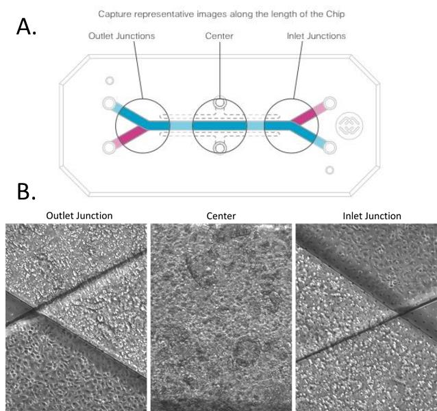
Figure 10. Representative schematic of image collection performed on chip. (A) Image capture of regions along the length of the chip. (B) Representative images of colonic epithelial cells and human microvascular endothelial cells seeded in the top and bottom chip channels, respectively.
Pre-dosing media condition change and PBMC thawing (Day 8)
Aspirate media from bottom channel inlet and outlet reservoirs.
Replace bottom channel media with ALI culture medium without hydrocortisone.
Note: Hydrocortisone is an immunosuppressant and needs to be removed a day before dosing.
Check for bubbles in the channel and vias, following standard troubleshooting procedures.
Maintain ALI setting.
PBMC thawing protocol (Day 8)
Heat PBMC culture medium to 37 °C in a water bath.
Thaw frozen vials, only three vials at a time, in a 37 °C water bath. When cells are nearly completely thawed, carry the vials to the hood and swipe them with 70% ethanol.
Take out PBMCs (by very slow and gentle pipetting) and transfer the cells into a 50 mL Falcon tube.
Dilution of DMSO: add 10 mL of warm complete medium dropwise, i.e., one drop per second, while gently mixing the cells. Use 1 mL to rinse out the vials.
Wash 1: spin the cells at 300 × g for 8 min at room temperature. Remove supernatant by tube inversion.
Wash 2: suspend the cell pellet in 1 mL of medium and add 9 mL of complete medium. Spin the cells at 300 × g for 8 min at room temperature.
Count cells and determine viability: add 1 mL of complete medium, slowly suspend the cell pellet using the 1 mL pipette, and add more medium to a cell concentration of approximately 3 × 10⁶ –4 × 10⁶ cells/mL (e.g., if the vial contained 20 × 106 fresh cells, add approximately 4 mL of medium since cell loss is expected after thawing). Perform the counting on 10 μL aliquots in duplicate with ½ trypan blue dilution. Just prior to pipetting out the cells for counting, gently invert the tube in order to homogenize the cell suspension.
Resting: adjust cell concentration to 2 × 10⁶ cells/mL in complete medium, transfer cells in a 25 or 75 cm2 flask, and let them rest for 4–16 h before performing the experiments. The flask should be kept standing or slightly bended, not flat in the incubator.
PBMC staining for live imaging (Day 9)
Transfer the PBMCs from the flask to a 50 mL conical tube and centrifuge at 300 × g for 8 min.
Resuspend the PBMC pellet with 10 mL of RPMI + 5% FBS and count the cell suspension.
Stain PBMCs with the CMFDA cell tracker green at a final concentration of 5 μM for 20 min at 37 °C and 5% CO2 .
Add 10 mL of media after the incubation time and centrifuge at 300 × g for 8 min.
PBMC pretreatment with TCBs (Day 9)
Resuspend PBMC cells with PBMC dosing medium (see Recipes) at a working concentration of 8 × 10⁶ cells/mL, or 2-fold higher than the final PBMC density.
Prepare TCBs in PBMC dosing media at working concentrations 2-fold higher than the final concentration specified in the experimental design.
Combine the 2-fold working concentrations of PBMCs with the corresponding TCBs.
Preincubate the dosing suspension for 1 h at 37 °C and 5% CO2 .
Reintroduction of liquid–liquid interface (LLI) (Day 9)
Add 500 μL of complete ALI medium (without hydrocortisone) in the top inlet reservoirs of all chips.
Make sure the bottom channel reservoirs have enough media. If not, add complete ALI medium (without hydrocortisone) to the bottom channel inlets.
Run a flush cycle to reintroduce liquid–liquid interface:
Set top channel flow rate to 1,000 μL/h and bottom channel flow rate to 0 μL/h.
Start flow and allow to run for 2 min.
Note: This step gently pushes media to the top channel and collects it in the top channel outlet reservoir.
Pause Zoë as previously described and move pods into the BSC. Aspirate all media from the top channel outlet reservoir.
Use the microscope to confirm that the top channel is submerged with medium.
If the top channel is not filled with medium, place back in the Zoë and run for another 1 min at 1,000 μL/h.
Repeat steps Z3c–Z3d as needed.
Set bottom and top channel flow rates to 30 μL/h and activate the Zoë.
PBMC-TCB introduction to the Alveolus Lung-Chip epithelium (Day 9)
Add 500 µL of the PBMC dosing medium to the top channel inlets in appropriate chips.
Run a flush cycle for the top channel:
Set top channel flow rate to 1,000 μL/h and bottom channel flow rate to 0 μL/h.
Start flow and allow to run for 3 min.
Pause Zoë as previously described and move pods into the BSC. Aspirate all media from the top channel outlet reservoir.
Disconnect the chips from Zoë and check under the microscope, making sure the PBMCs are distributed throughout the top channel (Figure 11).
Note: PBMCs might not be evenly distributed throughout the top channel after the flush cycle but will settle down evenly after the static period.
Place the chips back in the Zoë and leave the top channel static for 2.5 h to allow the PBMCs to settle.
Aspirate top channel inlets and outlets and refresh the top channel inlet reservoir with fresh dosing media.
Aspirate the bottom channel inlets and outlets and add fresh complete ALI medium (without hydrocortisone).
Connect the chips to flow and set the top and bottom channel flow rates to 30 µL/h.
Note: Record the time of PBMC-TCB dosing and the static incubation time.
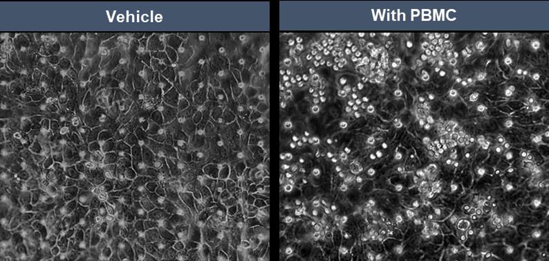
Figure 11. Representative brightfield micrographs of healthy alveolar epithelial cells on the top channel of the Alveolar Lung-Chip in the absence and presence of well-distributed PBMCs in co-culture
Timepoint collection and endpoints (Days 10 and 11)
Collect around 350 µL of effluent from the top and bottom outlet reservoirs and store at -80 °C immediately after collection.
Live imaging of apoptotic cells (Days 10 and 11)
Dilute NucView 405 at 1:500 with PBMC dosing medium.
Add 500 µL of this NucView medium solution to the top inlets of each chip.
Run flush cycle.
Set top channel flow rate at 1,000 µL/h and bottom channel at 0 µL/h for 5 min.
Stop flow and set the flow rate back to 30 µL/h for both channels for 30 min.
Aspirate top inlet and outlet reservoirs and replace with fresh complete ALI medium (without hydrocortisone).
Run flush cycle again to wash excess dye off the chip.
Set top channel flow rate at 1,000 µL/h and bottom channel at 0 µL/h for 5 min.
Image using fluorescence microscope. Take nine images per chip at a 10× magnification focused on the top channel from inlet to outlet.
PBMCs: GFP or green channel.
Apoptotic cells: DAPI channel.
Phase contrast: bright field.
Note: NucView 405 requires an exposure time of 500 ms.
Save images as .vsi or .tiff files for quantification of apoptotic epithelial cells.
Connect chips to Zoë and flow overnight at a flow rate of 30 µL/h in top and bottom channels.
An example of live imaging of apoptotic cells is shown in Figure 12.
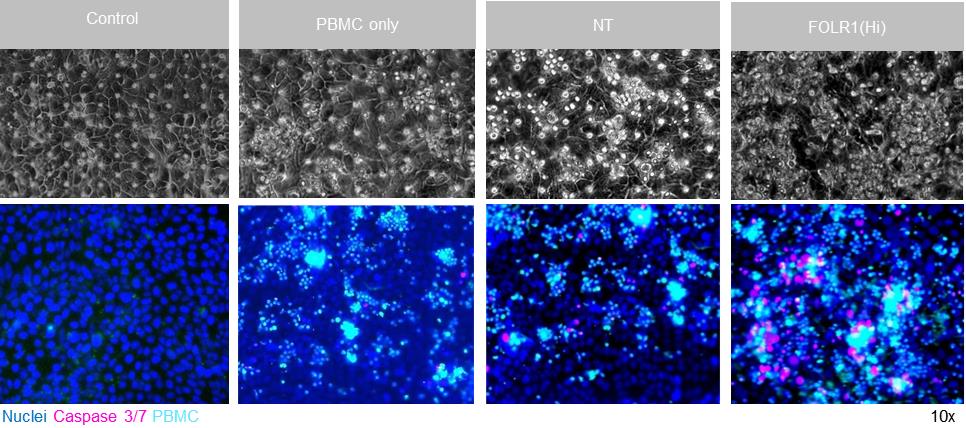
Figure 12. Representative brightfield (top) and immunofluorescent images (bottom) of Alveolar Lung-Chip epithelium (nuclei, blue) 48 h after addition of PBMC (cyan). The control group did not have PBMC administered. The FOLR1(Hi) group showed higher levels of PBMC attachment and caspase-3/7-positive, apoptotic cells (magenta).
PBMC collection for flow cytometry analysis (Day 11)
Disconnect chips from Zoë and pods.
Plug the bottom channel with tips on both ends and the top channel inlet.
Take 100 µL of complete ALI medium (without hydrocortisone) and triturate using a pipette, to collect as many PBMCs as possible from the top channel from each chip in separate tubes or wells of a V-bottom, 96-well plate.
Collect all remaining media from the top channel of chips as well in corresponding tubes or wells.
Add fresh complete ALI medium (without hydrocortisone) to the top channel of each chip.
Collect fluorescent images in the GFP channel of the top channel of chips after PBMC collection to enable downstream quantification of TCB-mediated PBMC attachment.
Fix chips for downstream immunofluorescent endpoints by applying 4% PFA solution for 20 min in both channels.
Wash both chip channels with DPBS and store for up to one week at 4 °C.
Centrifuge PBMCs collected in tubes or V-bottom, 96-well plates at 300 × g for 5 min.
Collect supernatant for downstream bioanalyte analysis.
Resuspend the PBMC pellets in 100 µL of FACs buffer (see Recipes).
Centrifuge at 300 × g for 5 min.
Discard supernatant and resuspend the pellets in each well with 50 µL of a master staining mix:
1 µL Anti-human CD3 HIT3a Alexa Flour 700.
1 µL Anti-human CD4 OKT4 BV785.
1 µL Anti-human CD69 FN50 BV650.
Remainder FACs buffer.
Incubate in the dark at 4 °C for 20 min.
Add 120 µL of FACS buffer to each well and centrifuge at 300 × g for 5 min.
Discard supernatants and resuspend the PBMC pellets in 200 µL of FACS buffer.
Centrifuge at 300 × g for 5 min.
Resuspend the pellet in 1% PFA solution for 15 min at room temperature.
Add 100 µL of FACS buffer and centrifuge at 300 × g for 5 min.
Discard the supernatant and resuspend the pellets in 200 µL of FACS buffer.
Cover with foil and store at 4 °C for up to one week for flow cytometry analysis.
QIFIKIT single-cell quantification of target antigen
Dissociation of epithelial cells from Alveolus Lung-Chip:
Note: It is recommended to have samples in triplicate (separate Organ-Chip per well), including an unstained control.
Wash chip channels twice with DPBS (1×).
Add tips to outlets of both channels with P200 pipette tips. Do not fully block the flow.
Add 100 µL of accutase to top and bottom channels.
Keep tips inside the top and bottom channel inlet ports and transfer chips to incubator (37 °C) for 5 min.
Check the dissociation of cells from the top channel by triturating the top channel epithelium using a P200 and checking under a microscope.
If more dissociation is required, repeat steps EE5–EE6 until cells are detached.
Note: This process usually takes from 15 to 20 min.
Collect the contents of the top channel only into Eppendorf tubes.
Break up the cells further by titrating with a P200 pipette.
Add 500 µL of medium 199 to quench the accutase digestion and pipette to mix.
Centrifuge at 350 × g for 5 min.
Resuspend pellet in 200 µL FACS buffer to wash.
Take a small volume (approximately 5 µL) of the sample of cell suspension and count using the hemocytometer.
Indirect immunofluorescence staining of cell surface antigens:
Centrifuge tubes at 350 × g for 5 min.
Resuspend the pellet in FACS buffer to adjust the cell concentration to 0.5 × 10⁶ cells/mL.
Transfer 100 µL (approximately 50,000 cells) of the target cell suspension into each well of V-bottom, 96-well plate, as indicated.
Centrifuge the plate and discard supernatant.
Add 50 µL of FACS buffer containing indicated amounts of primary antibody dilutions:
Anti-human FOLR1 diluted to 10 µg/mL. Ensure that the primary antibody is used at saturating concentration.
Mouse IgG1 isotype control diluted to 10 µg/mL.
Note: Allocate one extra well of epithelial cells as an unstained control.
Perform primary staining for 30 min at 4 °C in the dark.
Transfer 100 µL of vial 1 (setup beads) and vial 2 (calibration bead solution) (QIFIKIT® ) to two wells of a 96-well plate.
Next, wash cells (and beads) twice with FACS buffer.
Dilute QIFIKIT® anti-mouse IgG (FITC) 50× in FACS buffer.
Resuspend wells in 25 µL of FACS buffer containing anti-mouse IgG. Stain cells and beads for 30 min at 4 °C in the dark.
Wash wells once with FACS buffer.
Fix with FACS buffer + 1% PFA solution for 20 min at 4 °C.
Wash cells with FACS buffer and resuspended in 100 µL FACS buffer. Store in the dark at 4 °C until measurement.
Note: If taking multiple timepoints, samples can be kept in the dark at 4 °C for up to one week. Calibration and setup should be generated each time for staining controls.
Collection and analysis of QIFIKIT® data
Run samples using FACSDiva flow cytometer or equivalent system, using the setup beads to inform voltage settings.
Using FlowJo software, open the setup bead sample data and view in histogram plot with intensity of FITC-A as x-axis.
Gate the positive population as “FITC+” and calculate the geometric mean intensity.
Repeat for all experiment samples (using the unstained control and setup beads as getting reference) (Figure 13).
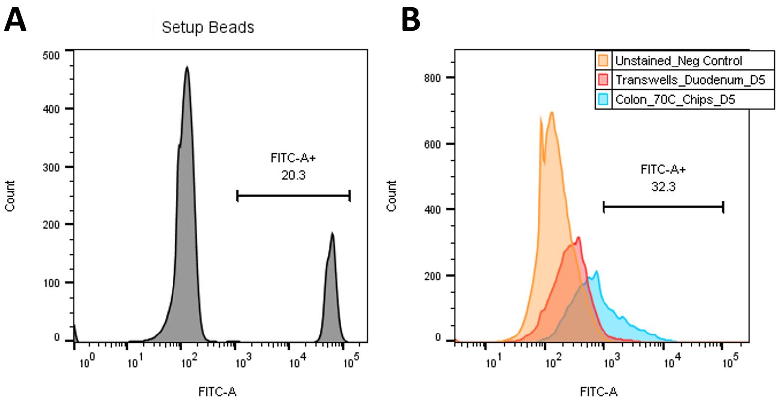
Figure 13. Example QIFIKIT® analysis. (A) Histogram of FITC signal for setup beads, with FITC+ signal selected. (B) Overlay of unstained control (orange), sample 1 (red), and sample 2 (blue) on FITC signal histogram to determine geometric mean of FITC+ signal.Calculate the standard curve and the number of antigenic sites present on the cell surface:
Open the calibration beads sample in histogram plot with five separate FITC intensity peaks.
Using the range gate tool, gate the separate peaks and obtain their geometric mean intensity of FITC-A signal.
Using the instructions provided in the QIFIKIT® kit, calculate the standard curve and apply to samples to report the number of antigenic target sites (Figure 14).
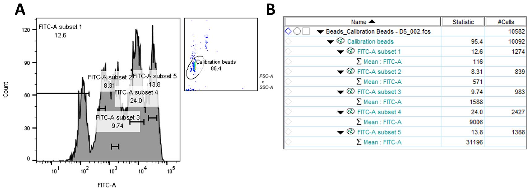
Figure 14. QIFIKIT® calibration beads in FlowJo. (A) Histogram of FITC signal showing five gated peaks of calibration beads. (B) For each peak, the geometric mean of FITC+ intensity is measured in order to produce the standard curve.Endpoint fixation with PFA
Note: Prepare the workspace of the chemical fume hood prior to beginning your work, ensuring that the space within the hood is organized and free from clutter and that the path of airflow is not blocked.
Ensure all chip carriers are labeled and identify the different conditions clearly. Detach chips from PodTM modules and organize them in petri dishes for handling.
Gently wash each channel with 200 μL of DPBS once.
Place 200 μL tips gently in the outlets of both channels. We recommend using filtered tips for this step. Be careful to not push the tips too hard against the bottom of the chip channel, as this could seal off the outlet and prevent reagents from going through the channel and outlet.
Add 100 μL of 4% PFA (in PBS, pH 7.4) to each channel from the inlet, leaving the tips inserted into the inlet as shown inFigure 7.
Incubate for 20 min at room temperature.
After incubation, remove all four pipette tips and wash each channel with 200 μL of DPBS three times.
Optional: Add 200 μL of 100 mM glycine to each channel and incubate at room temperature for 30 min [PFA tends to increase the sample auto-fluorescence in the green (FITC, 488) wavelength and glycine can be used to quench the autofluorescence].
Note: Fixed chips can be stored at 4 °C for up to one week in DPBS with 0.05% sodium azide. To ensure channels do not dry up during this period, it is recommended that DPBS is added with 200 μL tips as described in steps FF3 and FF4 above. Then, place the chips with tips in the ports inside plastic containers sealed with parafilm. We recommended using empty 200 μL tip boxes for storage. Ensure that the tips remain snug in the ports during transport and storage to avoid drying of the channels.
Permeabilization and blocking
Use PBS to prepare a blocking/permeabilizing solution containing:
0.1% Triton X-100 (it is recommended that permeabilization be skipped for surface markers).
1% BSA and 5% normal donkey serum (in DPBS) obtained from the same animal where secondaries antibodies have been raised in (species-matched serum).
Incubate the samples at room temperature for 30 min in the blocking/permeabilizing solution.
Wash samples with 200 μL of PBS three times.
Immunofluorescent staining on fixed samples
Prepare primary antibody staining solution(s) in 2% BSA/DPBS or 10% serum/DPBS:
Anti-human FOLR1 IgG1 1:50 (v/v).
Anti E-cadherin polyclonal rabbit (1:100).
After preparing the primary antibody solution(s), add 100 μL to the top and bottom channels, leaving pipette tips inserted in the inlet ports.
Incubate chips overnight at 4 °C.
After incubation remove all pipette tips and wash each channel with 200 μL of DPBS three times.
Prepare secondary antibody solution(s) in 2% (v/v) BSA in DPBS:
Donkey anti-mouse Alexa Flour 568.
Donkey anti-rabbit Alexa Flour 488.
Add 100 μL of the secondary antibody solution to the top and bottom channels, leaving pipette tips inserted in the ports as described in steps HH3 and HH4. If you are staining just one channel, add DPBS to the opposite channel.
Incubate chips for 2 h at room temperature taking care to protect them from light.
After incubation, remove all pipette tips and wash each channel with 200 μL of DPBS three times.
Prepare NucBlue solution: 2 drops of NucBlue solution in 1 mL of DPBS to stain cell nuclei. Add 100 μL of this solution and incubate for 10 min.
Wash three times with DPBS.
Image the samples (Figure 15) or store at 4 °C.
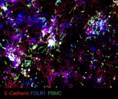
Figure 15. Example of immunofluorescent staining of FOLR1 target expression (blue) and E-cadherin (red) in epithelium of chips administered with FOLR1(Hi)-treated PBMC (green)
Data analysis
Alveolus Lung-Chip
PBMC attachment and epithelial cell apoptosis quantification
The images are saved as .vsi files; these need to be converted to .tiff before analyzing on ICY or ImageJ.
Convert .vsi to .tiff image type using FIJI:
Download FIJI software and install the Bio-Formats plugin (version 6.9.0 or higher) using the instructions provided here: https://docs.openmicroscopy.org/bio- formats/5.8.2/users/imagej/installing.html.
Open FIJI software.
Navigate to Process > Batch > Convert.
Choose Input and Output directory.
Select “Read Images Using BioFormats” box.
Select Convert.
These images can now be inputted in ICY image analysis software using the apoptosis protocol .
Open five random images on ICY to set the HK means and threshold for the entire set of images for both GFP (PBMC marker) and DAPI (apoptotic cells) channels to get optimal ROIs to run the entire protocol (in the example below, channel 1 is PBMCs and channel 2 is apoptotic cells).
Using co-localization tools, quantify the number of apoptotic epithelial-positive cells (Caspase-3+ NucView405+) that are also PBMC-cell-tracker-negative (GFP) and set different object sizes for alveolar epithelial cells (~900–3,000 pixels) and PBMCs (~200–600 pixels) in the ICY image analysis software.
Choose a directory to input images to be analyzed on ICY.
Input file name for analyzed images in the output.
Run the protocol. The results are displayed in Excel format.
A screenshot of the protocol is displayed below (Figure 16).
An example of a graph generated for apoptotic cells and PBMC attachment is shown in Figure 17.
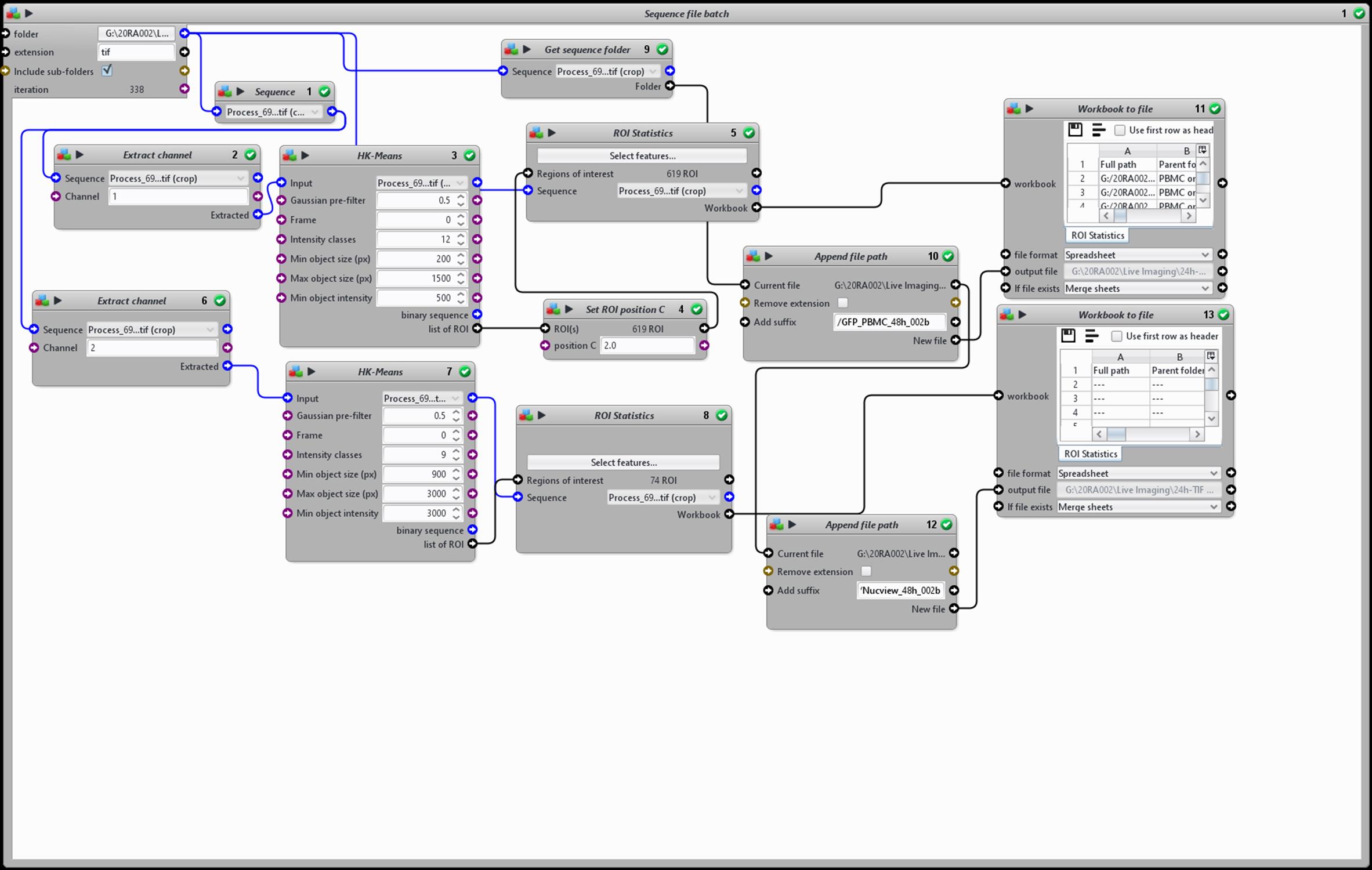
Figure 16. Schematic representation of the ICY image analysis protocol used to quantify immune cell attachment and epithelial cell apoptosis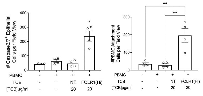
Figure 17. Example of quantification of apoptotic caspase-3/7-positive cells and PBMC attachment from live chips (n = 4). One-way ANOVA, Tukey’s multiple comparison test, *p < 0.05.Cytokine analysis
Collect affluents from Alveolus Lung-Chip pod outlets at 24 and 48 h after PBMC-TCB administration.
Immediately freeze effluents at -80 °C until measurement.
Measure cytokines for Alveolus Lung-Chip (GranzymeB, IFNg, IL-2, IL-6, IL-8, IL-10, IL-13, IL1RA, TNFa, MIP-1b, G-CSF, and GM-CSF) using the customized ProcartaPlex multiplex immunoassays.
ProcartaPlex multiplex immunoassays kit contains a black 96-well plate (flat bottom), antibody-coated beads, detection antibody, streptavidin-R-phycoerythrin (SAPE), reading buffer, and universal assay buffer. In addition, standards with known concentration are provided to prepare a standard curve.
According to the Invitrogen publication number MAN0017081 [Revision B.0 (33)], the assay workflow is as follows:
After adding the beads into the flat bottom plate, wash the beads using a flat magnet and an automated plate washer (405TS microplate washer from Bioteck).
Then, add standards and samples diluted with a universal buffer into the plate and incubate for 2 h.
After a second wash, add detection antibodies.
After 30 min incubation and a wash, add SAPE.
Finally, after 30 min incubation and a final wash, resuspend the beads in the reading buffer. The plates are ready for analysis.
Acquire the data with a BioPlex-200 system. Using the certificate of analysis provided with the kit, enter the bead region and standard concentration value S1 for each analyte of the current lot in the software BioPlex Manager.
Plotting the expected concentration of the standards against the mean fluorescent intensity generated by each standard, the software generates the best curve fit and calculates the concentrations of the unknown samples (in pg/mL).
The data is then exported in Excel and plotted in GraphPad Prism.
Flow cytometry
List of flow cytometry panel for PBMC:
PBMC: FITC
CD3: Anti-human CD3 HIT3a Alexa Flour 700
CD4: Anti-human CD4 OKT4 BV785
CD69: Anti-human CD69 FN50 BV650
CD25: Anti-human CD25 BC96 PerCP-Cy5.5
Apoptotic cells: Pacific blue
Acquire sample data using BD FACSCelestaTM flow cytometer and analyze data using FlowJo V10 software.
Open all samples in FlowJo software and copy single stain control samples into compensation group.
Use FlowJo compensation window to calculate a new compensation matrix and apply to all samples.
Apply gating strategy to samples, using the unstained and compensation control samples for guidance:
Open the unstained control sample and view in SSC-FSC dot plot.
Place a polygon gate to encircle the lymphocyte population.
Within lymphocyte population, determine the PBMC (FITC) population for live cells.
In the lymphocyte+/PBMC+ population, plot CD3 (Alexa Flour 700) vs. CD4 (BV786) population and gate CD3+ CD4- population to isolate CD8+ T cells.
Within the CD8+ gate, create a gate for CD69+ (BV650) to assess the activation of CD8+ T cells.
Report statistics of frequency of parent to Excel for plotting:
% lymphocyte+
% lymphocyte+/PBMC-FITC
% lymphocyte+/PBMC-FITC/CD3+ CD4-
% lymphocyte+/PBMC-FITC/CD3+ CD4-/CD69+
Note: Figure 18 shows an example of FACS panel for Colon-Chip using live/dead (BV605) to determine the live PBMC population. For the Alveolus-Chip experiments, PBMC cell tracker green was used instead to determine the live PBMC population. Either version can be used for FACS analysis.Figure 19shows a representative example of the relative populations of activated CD8+ T cells.
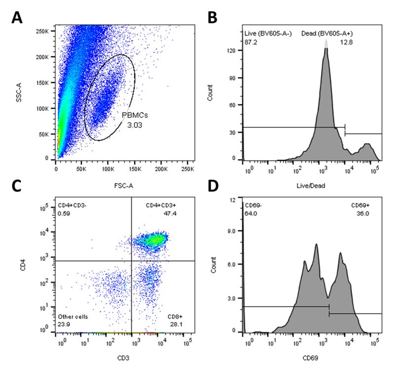
Figure 18. Example of flow cytometry analysis in FlowJo. (A) SSC-FSC dot plot of unstained control sample to select lymphocyte+/PBMC+ population. (B) Histogram of live/dead stain to gate on live cells. (C) Quadrant dot plot of CD3 and CD4 signal to select CD8+ population. (D) Histogram of CD69 signal to gate on CD69+ activated CD8 T cells.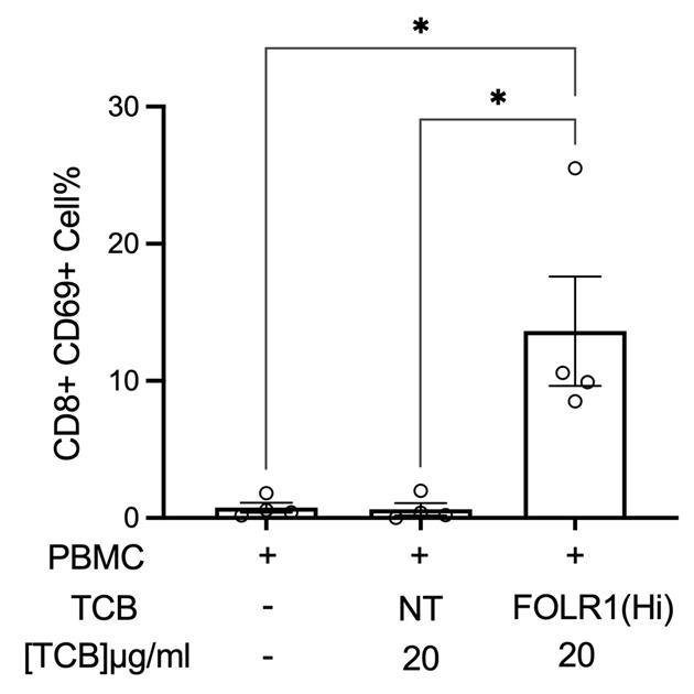
Figure 19. Example of flow cytometry analysis of PBMC harvested from chips for percentage of live, CD69+ activated CD8+ T cells (n = 4, approximately 10,000 cells per chip) after 48 h
Part II: Colon-Chip
Procedure
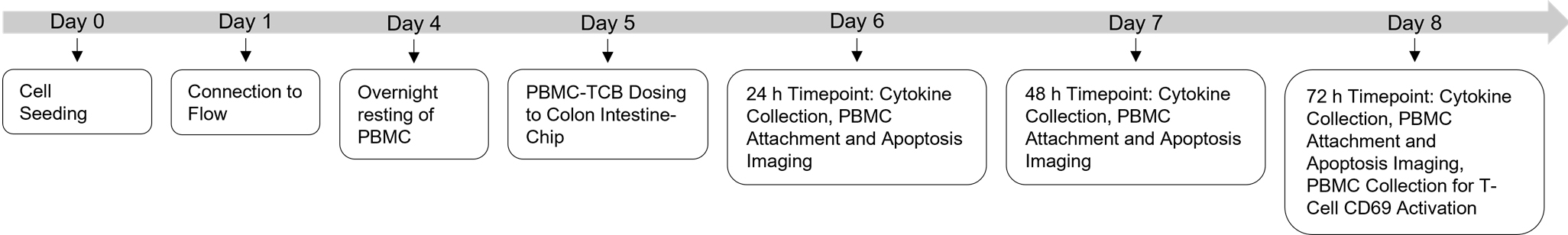
Figure 20. Experimental timeline for the culture of the human Colon Intestine-Chip
Isolation and cryopreservation of peripheral blood mononuclear cells (PBMCs)
Follow the instructions outlined in section A of Part I: Alveolar Lung-Chip protocol.
Thawing of human intestinal microvasculature endothelial cells (HIMECs) (Day -3)
Note: HIMECs are included in the Emulate Basic Research kit.
Heat 50 mL of HIMEC culture medium to 37 °C.
Add 5 mL of attachment factor onto the entire growth surface of a T-75 flask and incubate at 37 °C and 5% CO2 for 5 min.
Discard excess attachment factor.
Add 15 mL of HIMEC culture medium to the flask and leave it in a 37 °C incubator until ready for plating.
Thaw the vial(s) of cells by immersing in a 37 °C water bath.
Immediately transfer the contents of the vial using a P1000 pipette into the prepared T-75 flask containing warm HIMEC culture medium.
Incubate the flask at 37 °C and 5% CO2 for 6 h.
Aspirate medium and carefully add 15 mL of fresh HIMEC culture medium.
Return the flask back to the incubator at 37 °C and 5% CO2 overnight.
Exchange medium in flask with fresh HIMEC culture medium every other day until use for chip seeding.
Chip activation and preparation (Day -1)
Follow instructions outlined in section D of Part I: Alveolar Lung-Chip protocol. An overview of the timeline for the Colon Intestine-Chip experimental timeline is shown in Figure 20.
Chip coating with ECM (Day -1)
Follow procedure outlined in section E of Part I: Alveolar Lung-Chip protocol, with the following alterations:
In steps 2–4, use colon ECM working solution for bottom channel.
In steps 5 and 6, use colon ECM working solution for top channel.
Prepare chips for seeding (Day 0)
Gently wash each channel of the chip with 200 μL of warm complete HIMEC culture medium.
Aspirate the medium outflow at the surface of the chips, leaving the medium in the channels.
Repeat the wash with an additional 200 μL of complete HIMEC culture medium per channel, leaving the excess medium outflow covering the inlet and outlet ports.
Cover the 150 mm dish and place the chips in the incubator until the cells are ready for seeding.
Harvest of human intestine microvascular endothelial cells (HIMECs) (Day 0)
Aspirate culture media from a T-75 flask of confluent HIMECs.
Add 15 mL of DPBS to wash the culture surface and aspirate the DPBS wash.
Add 3 mL of TrypLE Express to the flask and incubate for 2–3 min at 37 °C and 5% CO2 .
Tap the side of the flask gently and inspect the culture under the microscope to assess complete detachment of cells from the flask surface.
Add 3 mL of warm complete HIMEC culture medium to the flask and pipette gently to mix, while collecting all cells from the flask surface.
Transfer the contents of the flask into a sterile 15 mL conical tube.
Pipette gently to create a homogeneous mixture and transfer 20 μL of the cell suspension to a 1.5 mL tube containing the cell counting solution of 20 μL of HIMEC culture medium + 20 μL of trypan blue, making a 1:3 dilution.
Mix the counting solution thoroughly and count cells using a manual hemocytometer.
Count both viable and non-viable cells.
Calculate percent viability of the cell solution.
The expected viability of the HIMECs should be greater than 80%.
Calculate viable cell concentration.
Discard cell counting suspension and calculate viable cell yield.
Centrifuge HIMEC suspension at 150 × g for 5 min at room temperature.
Carefully aspirate the supernatant, leaving approximately 100 μL of medium above the cell pellet.
Note: The cell pellet will be very small. Aspirate carefully.
Loosen the cell pellet by flicking the tube gently.
Using a P1000 pipette, gently resuspend the cells by adding 200 μL of warm complete HIMEC culture medium.
Dilute with warm complete HIMEC culture medium to the required final cell density of 8 × 10⁶ cells/mL viable HIMECs.
Seed HIMECs to bottom channel (Day 0)
Bring the 120 mm dish containing the prepared chips to the BSC.
Avoiding contact with the inlet and outlet ports, carefully aspirate excess medium droplets from the surface of one chip.
Very gently agitate cell suspension before seeding each chip to ensure a homogeneous cell suspension.
Using a pipette, pipette out the medium from the bottom channel, leaving it empty.
Quickly and steadily pipette 10–15 μL of the HIMEC cell suspension into the bottom channel inlet port, while aspirating the outflow fluid from the chip surface. Avoid direct contact with the outlet port.
Cover the dish and transfer to the microscope to check the seeding density within the chip (see Figure 21 for reference).
Note: At this stage, optimal seeding density should form an even layer with cell-to-cell spacing of approximately half the radius of a single cell.
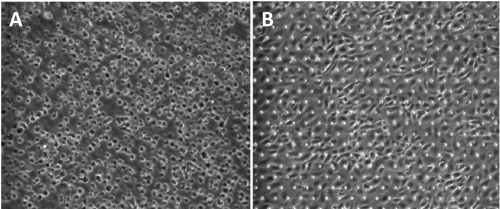
Figure 21. Endothelial (HIMEC) optimum cell seeding density. (A) Optimal seeding density under brightfield microscopy immediately after seeding into the bottom channel. (B) HIMECs attached on chip two hours post-seeding.If seeding density is not optimal, return the chips to the BSC and wash the channel with 200 μL of fresh medium two times. Do not aspirate the medium from the channel. Adjust cell density accordingly and repeat steps F3–F5 until the correct density is achieved within the channel.
After confirming the correct cell density, seed cells in the remaining chips, invert each chip, and rest the edge of the chip carrier on the chip cradle.
Note: Each chip cradle can support up to six chips inside a square cell culture dish (Figure 7).
Place DPBS at the cradle to provide humidity for the cells. Replace dish lid.
Note: Minimize the amount of time the cells are outside the incubator by seeding no more than 12 chips at a time and immediately placing them in the incubator at 37 °C and 5% CO2 after seeding each batch.
Place the chips still in the dish in the incubator at 37 °C and 5% CO2 for approximately 30 min–1 h, or until cells in the bottom channel have attached.
Once HIMECs have attached (approximately 1 h post-seeding), flip the chips back to an upright position.
Wash chips (Days 1 and 2)
Note: A gentle wash is performed 30 min–1 h post-seeding, once the cells have attached, to ensure that nutrients are replenished and that channels do not dry out. If cells are not attached, incubate overnight and then wash.
Gently pipette 200 μL of warm complete HIMEC culture medium to the top and bottom channels of each chip to wash. Aspirate the outflow, leaving media in the channel.
Repeat the step using complete IntestiCult expansion media to wash the top channel.
Harvest of colonoids (Day 0)
Note: Due to the donor-dependent protocol variation, this protocol assumes the user has in-culture expanded colonic organoid material from a primary, healthy donor. For more information on colonic organoid expansion and culture please see Sato et al. (2011) and Sontheimer-Phelps et al. (2020).
Carefully aspirate medium from each colonoid without disturbing the matrigel dome.
Gently add 500 μL of cell recovery solution to each well.
Scrape the matrigel using a cell scraper.
Using a P1000 pipette, collect contents of each well and transfer to a cold, LoBind 15 mL conical tube.
Incubate conical tube on ice for 45 min, inverting the tube every 2–5 min during this time.
While cells are incubating on ice, ensure the centrifuge is cooled down to 4 °C.
Centrifuge the organoid suspension at 300 × g for 5 min at 4 °C.
After centrifugation, observe the tube to confirm complete disappearance of matrigel and clear formation of a cell pellet.
Note: If a thin layer of matrigel is present, remove the supernatant carefully using a P1000 pipette without disrupting the pellet and add 5 mL of new cell recovery solution. Incubate for 5 min on ice and repeat centrifugation in Step H8. If no clear pellet is formed, repeat step H8.
Once a defined cell pellet is observed, aspirate the supernatant, gently flick the tube to disrupt the pellet, and add the prepared dissociation solution, 2 mL for every 24-well plate.
Incubate the conical tube in the water bath at 37 °C for 1–2 min to dissociate the organoids into fragments.
Note: Incubation time will vary based on the size of organoids; however, do not incubate for longer than 2 min, as this may result in dissociation of organoids into single cells, leading to decreased seeding efficiency.
Dilute at least two times with advanced DMEM/F12 medium to wash.
Centrifuge to pellet the dissociated organoids at 300 × g for 5 min at 4 °C.
Aspirate the supernatant and adjust seeding density by suspending the pellet in IntestiCult expansion media.
Adjust cell density (Day 0)
The seeding density depends on the size and density of organoids cultured on the 24-well plate. Use of two to three wells of organoids per chip has been recommended (Figure 12).
To calculate volume for suspension of dissociated organoids:
Chip seeding volume = 30 μL.
Number of chips = 6.
Volume of media required to resuspend dissociated organoids = 30 μL × 6 chips = 180 μL.
Dilute the organoids with warm IntestiCult expansion media to the required final cell density (see Figure 22).
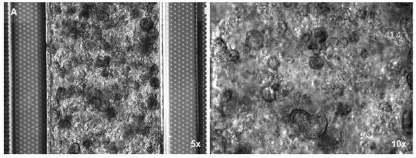
Figure 22. Optimal single and fragments organoids density.(A) Low magnification; (B) Higher magnification. Note that the porous membrane is completely covered by the cells.Seed colonoids to top channel (Day 0)
Note: Work with one chip at a time. After seeding the first chip, assess cell density within the channel through the microscope, adjusting the density of the cell suspension accordingly for the subsequent chips if necessary.
Pipette out the medium from the top channel, leaving it empty.
Very gently, agitate the cell suspension before seeding each chip to ensure a homogeneous mixture for even seeding.
Quickly and steadily, pipette 30 μL of the cell suspension into the top channel inlet. Avoid direct contact between the aspirator tip and the outlet port.
Cover the dish and transfer to the microscope to check the seeding density within the chip.
Note: At the optimal seeding density, the organoid fragments will form an even cell layer on the top channel of the chip, covering the whole chip membrane (Figure 11).
If seeding density is not optimal, return the chips to the BSC and wash the channel with 200 μL of fresh medium two times. Do not aspirate the medium from the channel. Adjust cell density accordingly and repeat steps J3–J5 until the correct density is achieved within the channel.
To avoid density gradient between chips, once the cells density is confirmed, transfer approximately 300 μL aliquots of the cell suspension to 1.5 mL low protein binding tubes.
Seed cells in the remaining chips.
Note: Minimize the amount of time the cells are outside the incubator by seeding no more than 12 chips at a time, immediately incubating them at 37 °C and 5% CO2 after seeding each batch.
Place the dish of chips with a filled DPBS reservoir at 37 °C and 5% CO2 and incubate undisturbed overnight.
Gas equilibration of media (Day 1)
Note: The media equilibration step is important for the success of Organ-Chip culture. Omission of this step will cause the eventual formation of bubbles in the chip, the pod, or both, which will in turn cause irregular flow and negatively impact cell viability. Minimize the time media is outside of a warmed environment to no more than 10 min, as gas equilibrium can become compromised when media is allowed to cool.
Prepare at least 3 mL of HIMEC culture medium for each chip in a 50 mL conical tube.
Prepare at least 3 mL of IntestiCult expansion media for each chip in a separate 50 mL conical tube with the addition of 10 μM Y-27632, 5 μM CHIR99021, and a tracer of your choice to check the permeability. The most common one is the 3 KDa Dextran Cascade Blue at final concentration in medium of 100 µg/mL. The tracer can be kept in culture medium throughout the course of the experiment to ensure a tighter barrier function. The permeability assay section will provide further instructions.
Note: Approximately 2 mL of medium will be used per reservoir of the chip. For 12 chips, prepare approximately 30 mL of medium for the top channel and 30 mL of medium for the bottom channel.
As noted above, minimize the time media is outside of the incubator during pod preparation to maintain temperature. This is a critical step to ensure success of the chips.
Follow steps 3–10 in section N of Part I: Alveolar Lung-Chip protocol [Gas equilibration of media (Day 4)] to complete gas equilibration of media.
Media priming of pods (Day 1)
Open the pod package and place the pods into the trays. Orient the pods with the reservoirs toward the back of the tray (Figure 9A).
Pipette 2 mL of pre-equilibrated, warm media to each inlet reservoir. In the top channel inlet reservoir, add complete IntestiCult expansion medium; in the bottom channel inlet reservoir, add Complete HIMEC culture medium (Figure 9C).
Pipette 300 μL of pre-equilibrated, warm media to each outlet reservoir, directly over each outlet via (Figure 9C).
Follow steps 4–16 in section O of Part I: Alveolar Lung-Chip protocol [Media priming of pods (Day 4)].
Wash chips (Day 1)
Transfer the seeded chips in a 120 mm square dish from the incubator to the BSC.
Wash twice the top channel of each chip with 200 μL warm equilibrated IntestiCult expansion media, aspirating the outflow from the chip surface.
Wash the bottom channel of each chip with warm, equilibrated HIMEC culture medium, aspirating outflow from the chip surface.
Place small droplets of equilibrated IntestiCult expansion media on all inlet and outlet ports of the top channel and HIMEC culture medium on the inlet and outlet of the bottom channel.
Repeat steps M2–M4 for each chip.
Chips-to-Pods (Day 1)
Follow procedure outlined in section Q of Part I: Alveolar Lung-Chip protocol [Chips-to-Pods (Day 4)].
Pods-to-Zoë (Day 1)
Follow procedure outlined in section R of Part I: Alveolar Lung-Chip protocol [Pods-to-Pods (Day 4)].
Alevolar-Chip via wash and the regulate cycle (Day 2)
Follow procedure outlined in section S of Part I: Alveolar Lung-Chip protocol [Via wash and the regulate cycle (Day 5)].
Colon-Chip via wash and the regulate cycle (Day 2)
Replenish media in the top inlet reservoir with IntestiCult maintenance media (without the addition of Y-27632 and CHIR99021 inhibitors).
Add HIMEC culture medium to the bottom inlet reservoir.
Replace pod lids.
Inspect the chip for bubbles.
Initiating mechanical stretch (Day 3)
Pause Zoë by pressing the silver “Activation” button.
Using the rotary dial, highlight the “Stretch” field.
Press the dial to select “Stretch” and rotate the dial clockwise to increase stretch to “2%.”
Press the dial to select “Freq.” and rotate the dial clockwise to increase stretch to “0.15 Hz.”
Sampling and maintenance (Day 4)
Follow protocol outlined in section V of Part I: Alveolar Lung-Chip protocol (Sampling and media replenishment).
Permeability assay (Day 2+)
Notes:
This protocol is to assess the permeability of an Organ-Chip's endothelial-epithelial barrier. Apparent permeability (Papp) of tracer molecules is determined by dosing the inlet of the top channel, collecting the effluent of both top and bottom channels, and calculating the amount of compound that crossed through the membrane over time. A recommended tracer molecule is Dextran Cascade Blue 3000MW (Thermo Fisher, catalog number: D7132).
It is recommended to prepare and analyze the permeability assay samples fresh for each timepoint day.
Prepare standard curves of the fluorescent tracer molecule (i.e., Dextran Cascade Blue) used in your permeability assay in both the dosing channel media as well as receiving channel media. This is required to quantify and further analyze barrier integrity on the Organ-Chip.
Start by preparing at least 500 μL of a solution of fluorescent tracer dissolved in the dosing media at the same concentration that is added to the dosing channel reservoir. (You can prepare a larger volume if needed to accommodate a greater dilution of the tracer.) Label this as solution 1 .
Label seven other tubes 2–8 and add 200 μL of the respective media (dosing or receiving channel media) to each of the tubes.
Take 200 μL solution from tube 1 and add to 2, mixing evenly by pipetting up and down a few times. Then collect 200 μL from 2 and add to 3, continuing this way until you have prepared a serial dilution until tube 7. Add media without compound to tube 8, which will be used as the blank.
Repeat this serial dilution for receiving channel media but start with a concentration of the fluorescent molecule that is 25% of the concentration added to the donor channel reservoir. (This is done to align the standard curve with the expected recovery concentrations.) Label tubes 9–16.
Load a 96-well plate with either 50 or 100 μL (as per the requirements of your plate reader) of each of the solutions from tubes 1–16 (standards), as well as samples collected while running the barrier function assay. Load your plate and read on a plate reader.
Using the standard curves generated by the plate reader, quantify the concentration of each sample, making sure to use the curve used for the media type being analyzed (e.g., top or bottom channel).
A linear relationship is expected between concentration and plate reader output—check to ensure that the data is indeed linear in the concentration range being measured from the samples, especially the receiving channels, which is expected to be a much lower concentration than the donor channel.
Perform a linear regression on the standard curve data to determine the equation of the form Y = m*X + b, which is needed to correlate plate reader data to concentrations.
Correlate plate readings to data using the regression equation. The Emulate Standard Curve Calculator (EC003, https://emulatebio.com/protocol-archive/ep187-v1-0) automatically generates the standard curves and converts inputted data based on the curve generated. This calculator performs a log-log linear regression analysis, which minimizes the percent error across the full range of the standard curve data.
Once all the concentrations have been calculated, Papp can be calculated using the following equation, which accounts for any loss of compound by assuming first-order loss dynamics along the length of the chip:

where,
Papp is the apparent permeability in units of cm/s;
SA is the surface area of sections of the channels that overlap (0.17 cm2);
QR and QD are the fluid flow rates in the dosing and receiving channels, respectively, in units of cm3/s;
CR,0 and CD,0 are the recovered concentrations in the dosing and receiving channels, respectively, in any consistent units.
The Emulate Papp Calculator (EC004) automatically performs this calculation (https://emulatebio.com/protocol-archive/ep187- v1-0).
Sample data is shown below in Figure 23 to illustrate expected Papp over time for healthy Colon Intestine-Chips (“Control”) compared to chips with barrier disrupted by cytokine IFNγ. Seeded Colon Intestine-Chip typically forms an intact barrier around day 3–5, corresponding to apparent permeability below 1 × 10⁻⁶ cm/s (https://emulatebio.com/support/ep203-v1-0/).
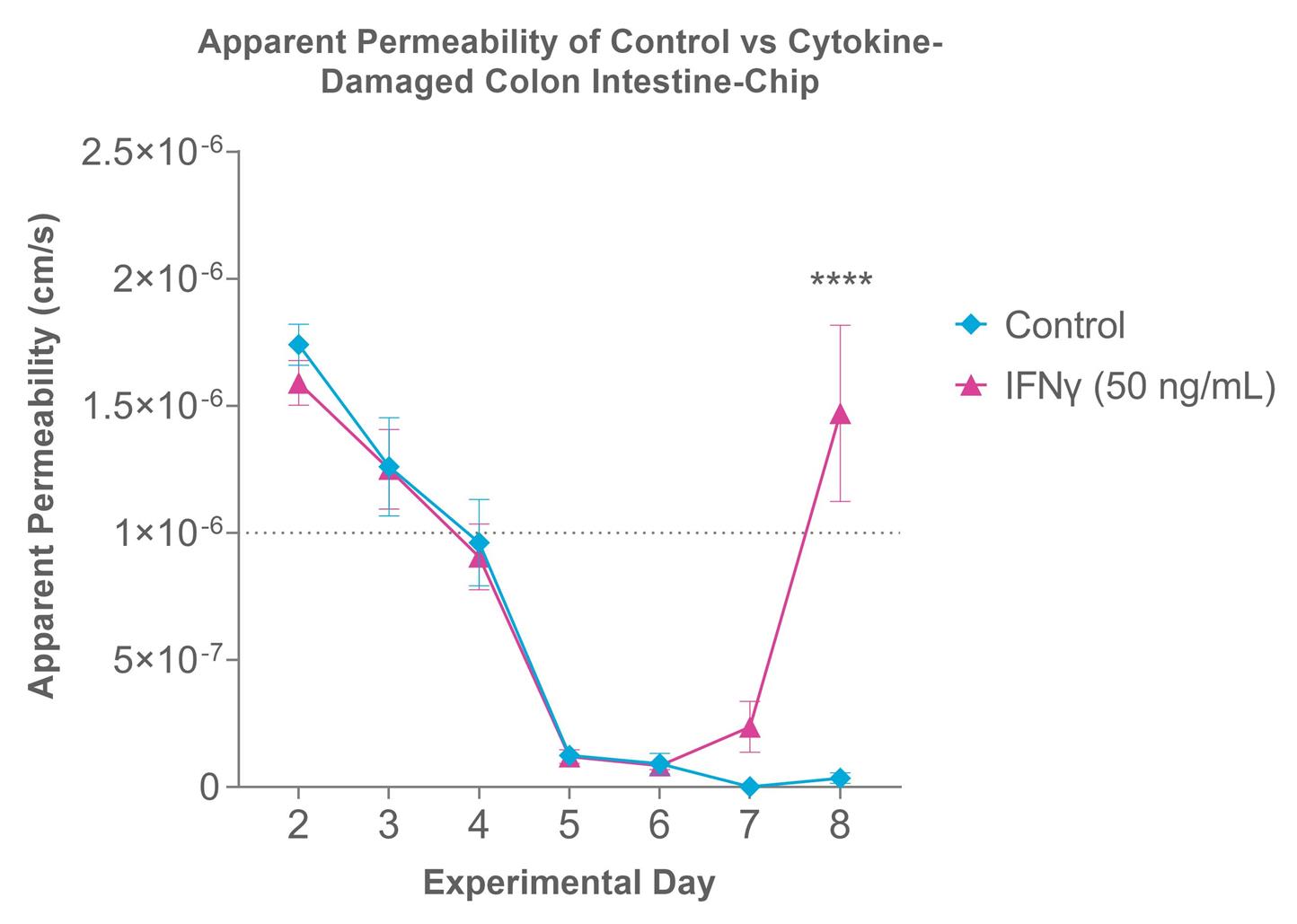
Figure 23. Sample Papp of Colon Intestine-Chip. Control Colon Intestine-Chip forms an intact barrier around experimental days 3–5, depending on seeding density. Intact barrier threshold marked by dotted line at y = 1 × 10⁻⁶ cm/s, which should be used as a guideline. Compared to healthy control (“Control”, blue line), cytokine treatment by IFNγ (pink line) replicates the damage of unhealthy permeable barrier (note: IFNγ treatment not included in this protocol).Increase stretch to 10% (Day 4)
Pause Zoë by pressing the silver “Activation” button.
Using the rotary dial, highlight the “Stretch” field.
Press the dial to select “Stretch” and rotate the dial clockwise to increase stretch to “10.0%.”
Press the dial to select “Freq.” and rotate the dial clockwise to increase stretch to 10% and the frequency to 0.15 Hz.
Press the “Activation” button.
PBMC thawing protocol (Day 4)
Follow protocol outlined in section X of Part I: Alveolar Lung-Chip protocol [PBMC thawing protocol (Day 9)].
PBMC staining for live imaging (Day 5)
Transfer the PBMCs to be stained from flask to a 50 mL conical tube and centrifuge at 300 × g for 8 min.
Resuspend the PBMC pellet with 10 mL of RPMI + 5% FBS and count the cell suspension.
Stain PBMCs with CMFDA cell tracker green at a final concentration of 5 μM for 20 min at 37 °C and 5% CO2 .
Add 10 mL of PBMC culture media after the incubation time and centrifuge at 300 × g for 8 min.
Follow protocol outlined in section Y of Part I: Alveolar Lung-Chip protocol [PBMC staining for live imaging (Day 10)].
PBMC pretreatment with TCBs (Day 5)
On the day of PBMC administration to chip, collect the PBMCs from culture flasks into 50 mL conical tubes.
Rinse flask with 10 mL of DPBS to collect as many PBMCs as possible.
Centrifuge the PBMCs for 8 min at 300 × g .
Resuspend the PBMCs in IntestiCult maintenance media at 8 × 10⁶ cells/mL, or 2-fold higher than the final PBMC density.
Prepare TCBs in PBMC dosing media at working concentrations 2-fold higher than the final concentration specified in the experimental design.
Combine the 2-fold working concentrations of PBMCs with the corresponding TCBs.
Divide the suspension into a 6-well plate (Falcon), separated by treatment condition.
Account for at least 500 µL of suspension for each chip.
Allow the PBMC to incubate at 37 °C and 5% CO2 with TCB antibodies for at least 1 h.
PBMC-TCB introduction to the Colon-Chip epithelium (Day 5)
Aspirate the pod inlets:
Pause Zoë by pressing the silver “Activation” button.
Remove the trays and place in the BSC.
Visually inspect each chip for bubbles.
Using a microscope, inspect cells in the chips to assess morphology and viability. Capture representative images at 10× or 20× magnification.
Remove the pod lids and collect effluent medium from pod outlet reservoirs for analysis.
Collect effluent from the indicated regions, avoiding disturbing the pod reservoir vias.
Collect effluents for downstream endpoint analysis.
Gently aspirate any medium not collected for analysis, ensuring that a thin liquid film still covers the reservoir vias so that no air is introduced into the vias.
Add 500 µL of the dosing solution to the top channel inlets in appropriate chips.
Mix the PBMC-TCB suspensions well with a P1000 pipette before administering.
Note: For appropriate PBMC-free controls, add only IntestiCult maintenance media.
To the endothelial channel pod inlet reservoir, add 500 µL of EGM2-MV complete medium.
Place pods in Zoë culture module.
Flow at 1,000 µL/h at 10% stretch (0.15 Hz) for 10 min.
Disconnect from Zoë and check under the microscope making sure the PBMCs are distributed throughout the top channel.
Aspirate all media from top channel outlet reservoir.
Resume flow at 30 μL/h overnight for top and bottom channels.
Note: PBMCs might not be evenly distributed throughout the top channel after the flush cycle but will settle down evenly after the static period.
Connect the chips to flow and set the top and bottom channel flow rates to 30 µL/h.
Note: Record the time of PBMC-TCB dosing and the static incubation time.
Timepoint collection and endpoints (Days 5, 6, 7, 8+)
Collect approximately 350 µL of effluent from the top and bottom outlet reservoirs and store at -80 °C immediately after collection.
Live imaging of apoptotic cells (Days 5, 6, 7, 8+)
Follow procedure outlined in section DD of Part I: Alveolar Lung-Chip protocol [Live imaging of apoptotic cells (Day 11 and 12)].
PBMC collection for flow cytometry analysis (Days 6, 7, 8+)
Disconnect chips from Zoë and pods.
Plug the bottom channel with tips on both ends and the top channel inlet.
Take 100 µL of IntestiCult maintenance media and triturate using a pipette to collect as many PBMCs from the top channel of each chip as possible in separate tubes or wells of a V-bottom, 96-well plate.
Collect all remaining media from the top channel of chips as well in corresponding tubes or wells.
Add fresh IntestiCult maintenance media to the top channel of each chip.
Collect fluorescent images in the GFP channel of the top channel of chips after PBMC collection to enable downstream quantification of TCB-mediated PBMC attachment.
Fix chips for downstream immunofluorescent endpoints by applying 4% PFA solution for 20 min in both channels.
Wash both chip channels with DPBS and store for up to one week at 4 °C.
Centrifuge PBMCs collected in tubes or V-bottom 96-well plates at 300 × g for 5 min.
Collect supernatant for downstream bioanalyte analysis.
Resuspend the PBMC pellets in 100 µL of FACs buffer.
Add 2 mM live/dead fixable yellow dead stain (see preparation) and incubate for 30 min at 37 °C.
Wash cells with 100 µL of DPBS.
Centrifuge at 300 × g for 5 min.
Discard supernatant and resuspend the pellets in each well with 50 µL of a master staining mix:
1 µL of Anti-human CD3 HIT3a APC-Cy7.
1 µL of Anti-human CD4 OKT4 BV785.
1 µL of Anti-human CD8 SK1 PE/Dazzle-594.
1 µL of Anti-human CD69 FN50 APC.
1 µL of Anti-human CD25 BC96 PerCP-Cy5.5.
Remainder FACs buffer.
Incubate in the dark at 4 °C for 20 min.
Follow steps 14–21 in section EE of Part I: Alveolar Lung-Chip protocol [PBMC collection for flow cytometry analysis (Day 12)] to complete flow cytometry workflow.
QIFIKIT® single-cell quantification of target antigen
Dissociation of epithelial cells from Colon Intestine-Chip:
Note: It is recommended to have samples in triplicate (separate Organ-Chip per well), including an unstained control.
Wash chip channels twice with DPBS (1×).
Add tips to outlets of both channels with P200 pipette tips and do not fully block flow.
Add 100 µL of TrypLE Express to top and bottom channels.
Keep tips inside top and bottom channel inlet ports and transfer chips to incubator (37 °C) for 2–3 min.
Check the dissociation of cells from the top channel by triturating the top channel epithelium using a P200 and checking under a microscope.
If more dissociation is required, repeat steps CC5–CC6 until cells are detached.
Note: This process takes usually from 15 to 20 min. Avoid excessive TrypLE incubation as this could damage surface epitopes.
Collect the contents of the top channel only into Eppendorf tubes.
Break up the cells further by titrating with a P200 pipette.
Add 500 μL of serum-free advanced DMEM/F12 (+1% Pen-Strep) to quench the TrypLE digestion. Pipette to mix.
Centrifuge at 350 × g for 5 min.
Resuspend pellet in 200 µL of FACS buffer to wash.
Take a small sample volume (approximately 5 µL) of cell suspension and count using hemocytometer.
Indirect immunofluorescence staining of cell surface antigens:
Centrifuge tubes at 350 × g for 5 min.
Resuspend the pellet in FACS buffer to adjust the cell concentration to 0.5 × 10⁶ cells/mL.
Transfer 100 µL (approximately 50,000 cells) of the target cell suspension into each well of V-bottom, 96 well plate, as indicated.
Centrifuge the plate and discard supernatant
Add 50 µL of FACS buffer containing indicated amounts of primary antibody dilutions:
Anti-human CEACAM5 diluted to 10 µg/mL.
Mouse IgG2a isotype control diluted to 10 µg/mL.
Note: Allocate one extra well of epithelial cells as an unstained control.
Follow steps 2f–2m of section EE of Part I: Alveolar Lung-Chip protocol to complete QIFIKIT® sample workflow.
Follow step 3 of section EE of Part I: Alveolar Lung-Chip protocol to complete QIFIKIT® analysis workflow.
Endpoint fixation with PFA
Note: Prepare the workspace of the chemical fume hood prior to beginning your work, ensuring that the space within the hood is organized, free from clutter, and the path of airflow is not blocked.
Follow procedure outlined in section GG of Part I: Alveolar Lung-Chip protocol (Endpoint fixation with PFA).
Permeabilization and blocking
Follow procedure outlined in section HH of Part I: Alveolar Lung-Chip protocol (Permeabilization and blocking).
Immunofluorescent staining on fixed samples
Prepare primary antibody staining solution(s) in BD perm/wash buffer:
For untreated samples without TCB:
Recombinant rabbit anti-CEA diluted 1:100 (v/v).
Monoclonal rat anti-CD45 diluted 1:100 (v/v).
For samples treated with TCB:
Monoclonal rat anti-CD45 diluted 1:100 (v/v)
After preparing the primary antibody solution(s), add 100 μL to the top and bottom channels, leaving pipette tips inserted in the inlet ports.
Incubate chips overnight at 4 °C.
After incubation, remove all pipette tips and wash each channel with 200 μL of DPBS three times.
Prepare secondary antibody solution(s) in CytoPerm/wash buffer.
For untreated samples without TCB:
DRAQ5TM diluted 1:250 (v/v).
DyLightTM 405 AffiniPure donkey anti-rat IgG (H+L) diluted 1:500 (v/v).
Donkey anti-rabbit Alexa FluorTM 555 diluted 1:500 (v/v).
For samples treated with TCB:
DRAQ5TM diluted 1:250 (v/v).
DyLightTM 405 AffiniPure donkey anti-rat IgG (H+L) diluted 1:500 (v/v).
Goat anti-human Alexa FluorTM 555 diluted 1:500 (v/v). This secondary is used since the CEA target sites were bound with anti-human TCB after administration.
Add 100 μL of the secondary antibody solution to the top and bottom channels, leaving pipette tips inserted in the ports as described in steps FF3 and FF4. If you are staining just one channel, add DPBS to the opposite channel.
Incubate chips for 2 h at room temperature taking care to protect them from light.
After incubation, remove all pipette tips and wash each channel with 200 μL of DPBS three times.
Data analysis
Colon-Chip
Quantifying PBMC attachment to epithelium
Note: Images acquired on Zeiss products are in Carl Zeiss Image Data (CZI) format; convert to Tag Image File Format (TIFF) to analyze.
If tile images were acquired, stitch the tile images together using Zen Blue:
Navigate to Processing tab.
Under Method, choose “Stitching.”
Under Parameters, select “Fuse Tiles.”
Select “Apply” to export stitched tile images.
Convert CZI to TIFF image type using FIJI.
Download FIJI software and install Bio-Formats plugin (version 6.9.0 or higher) using the instructions provided here: https://docs.openmicroscopy.org/bio- formats/5.8.2/users/imagej/installing.html.
Open FIJI software.
Navigate to Process > Batch > Convert…
Choose Input and Output directory.
Select “Read Images Using BioFormats” box.
Select Convert.
Open TIFF images in FIJI to determine optimal threshold values for detecting PBMC (CD45) signal.
Note: For best results, choose images in focus with the highest PBMC (CD45) signal.
For Brightness & Contrast adjusting:
Open the Brightness & Contrast window (Image > Adjust > Brightness/Contrast).
Select “Auto” on an in-focus image.
Note: Use the minimum and maximum values (circled in blue) for a few images to get an average (Figure 24).
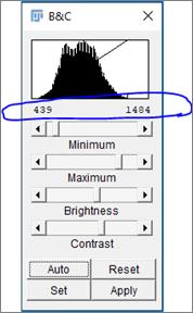
Figure 24. FIJI Brightness & Contrast menu with minimum and maximum histogram values circled blue. The Auto button (bottom left) sets these automatically for best signal.For PBMC intensity threshold optimizing:
Subtract Background of the image:
Process > Subtract Background… (radius = 50 pixels).
Filter out the noise with Median Filter:
Process > Filters > Median (radius= 2 pixels).
Threshold the image (Image > Adjust > Threshold) and choose the method that best captures the particles of interest (Figure 25).
Notes:
1) For a useful explanation comparing the Thresholding types, visit https://imagej.net/Auto_Threshold.
2) In the work published in Kerns et al. (2021), the Otsu threshold method was used.
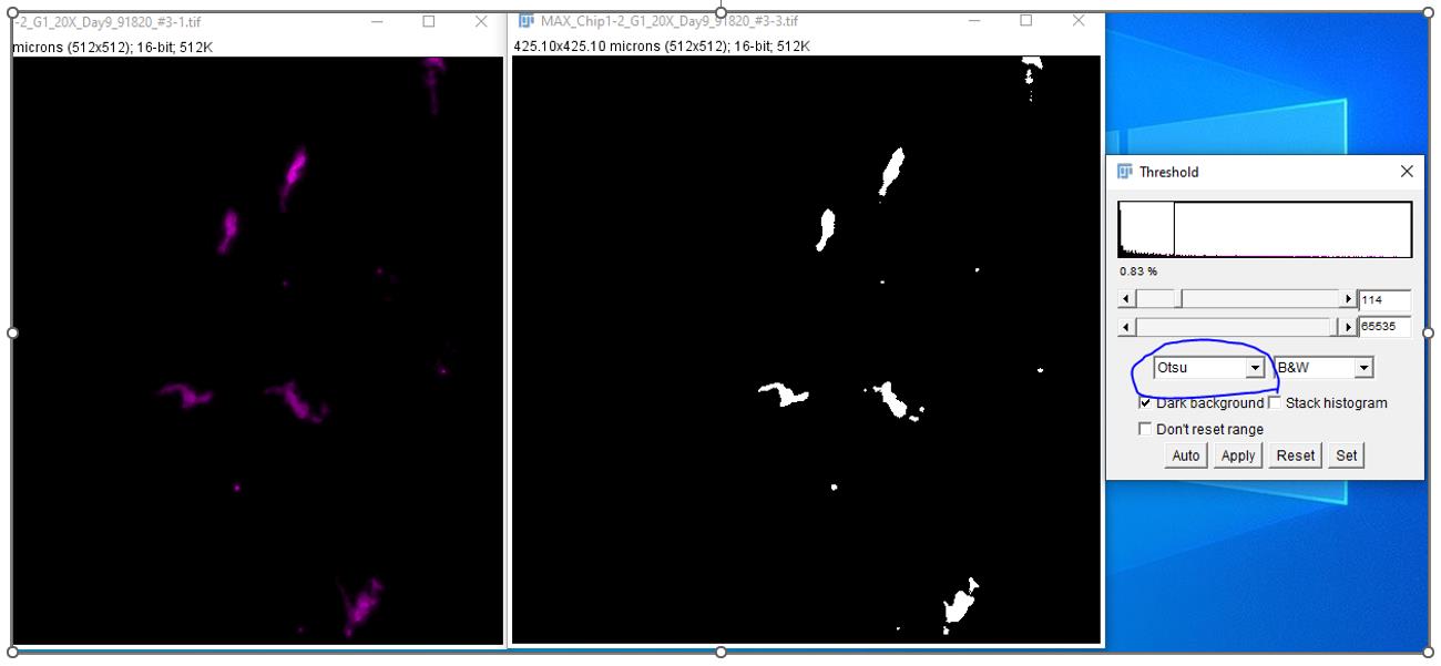
Figure 25. Determining the most accurate Auto Thresholding method (drop-down list circled in blue). Original image on left and the binary (black and white) Auto Threshold image on right.For PBMC size threshold optimizing:
Using the Auto-Threshold binary image, use the “Oval” elliptical selection tool to encircle a single particle or cluster of PBMC.
Use Analyze > Measure to get particle area in microns2 .
Repeat for multiple particles until you have a range of PBMC cluster sizes.
Note: In the work published in Kerns et al. (2021), the PBMC cluster size was found to be 15.9–106 mm2 with images taken at 40× magnification .
After intensity and size threshold have been set, quantify number of clusters of PBMC using the pre-determined values (Figure 26):
Note: Use a macro in Fiji to batch process multiple images.
Open image in FIJI.
Image > Adjust > Brightness/Contrast > Set.
Set Minimum and Maximum displayed value to values determined in step 3.
Process > Subtract Background… (radius = 50 pixels).
Process > Filters > Median (radius= 2 pixels).
Image > Adjust > Threshold (use previously determined method).
Analyze > Analyze Particles…
Size micron2 = previously determined range in step 5.
Select “Display Results” option.
Plot total count of PBMC clusters per sample.
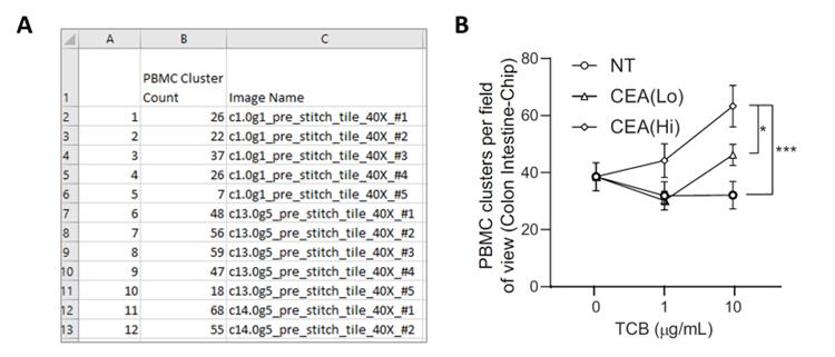
Figure 26. Sample quantification of PBMC clusters on Colon Intestine-Chip. (A) Excel output file from FIJI analysis with quantified number of PBMC clusters per image. (B) Typical plotted data using GraphPad Prism to compare treatment groups.Flow cytometric analysis of PBMC using FlowJo
List of flow cytometry panel for PBMC:
CD3: Anti-human CD3 HIT3a APC-Cy7
CD4: Anti-human CD4 OKT4 BV785
CD8: Anti-human CD8 SK1 PE/Dazzle-594CD69: Anti-human CD3 HIT3a APC-Cy7
CD25: Anti-human CD25 BC96 PerCP-Cy5.5
Live/dead yellow: BV605
Open all samples in FlowJo software and copy single stain control samples into compensation group.
If compensation of signals has not already been performed, use FlowJo Compensation window to calculate a new compensation matrix and apply to all samples.
Apply gating strategy to samples, using the unstained and compensation control samples for guidance:
Open the unstained control sample and view in SSC-FSC dot plot.
Place a polygon gate to encircle the lymphocyte population [you can also use CD3+ (APC-Cy7+) signal to determine this gate].
Within lymphocyte population, determine the live/dead negative (BV605-A-) population for live cells.
In the lymphocyte+/live/dead- population, create a gate for CD8+ (PE/Dazzle-594+) signal to isolate the cytotoxic T cell population.
Within the CD8+ gate, create a gate for CD69+ (APC+) to assess the activation of CD8+ T cells.
Report statistics of frequency of parent to Excel for plotting:
% lymphocyte+
% lymphocyte+/live/dead-
% lymphocyte+/live/dead-/CD8+
% lymphocyte+/live/dead-/CD8+/CD69+
Note: It is recommended to only include data with at least 500 counts (#Cells) for analysis.
Cytokine analysis
Collect at least 50 µL of pod inlet and outlet media at 0, 24, 48, and 72 h post PBMC-TCB administration.
Immediately freeze samples at -80 °C until measurement.
Using a customized Invitrogen ProcartaPlex multiplex immunoassay, follow manufacturer instructions to assess levels of IFNγ, TNFα, Granzyme-B, IL-2, IL-4, and IL-8.
Follow procedure outlined in Invitrogen documentation publication number MAN0017081 (Revision B.0 (33)).
Acquire samples on Luminex BioPlex-200 system (Bio-Rad) using BioPlex Manager software.
Plot the expected concentration of the standards against the mean fluorescent intensity generated by each standard and best curve fit and calculate the concentrations of the unknown samples (in pg/mL).
Export the data in Excel and plot in GraphPad Prism.
Notes
This protocol has been validated specifically using the Emulate Organ-Chips with Zoë® Culture Module and Orb Hub Module. This cohesive system supports continuous fluid flow to two microfluidic channels while providing physiological stretch, which are crucial to the development of the Alveolus Lung-Chip and Colon Intestine-Chip. Using an alternative technology is not recommended as this would result in a different and unproven model.
The recommended reagents in the above procedure specify the carcinoembryonic antigen (CEA) and folate receptor 1 (FLOR1) antigen targets for the colon and alveolar lung, respectively. The specification of these targets is based on the work described in the associated publication (Kerns et al., 2021); however, other relevant cellular targets and reagents can be considered and deployed using the approaches described in this protocol.
PBMCs isolated from donor whole blood are the cells’ source used in the protocol above to assess T cell activation and killing of targeted epithelial cells. PBMCs are comprised of a variety of specialized immune cells; the largest fraction of which are lymphocytes that include T cells, B cells, and Natural Killer Cells. While other immune cell types do express the T-cell receptor (TCR), expression of the TCR is the defining characteristic of T cells and they are therefore the cell type most significantly impacted by the TCR targeting function of TCB antibodies. This is a logical conclusion that is supported by the T cell–specific responses that are observed upon the co-administration of TCBs and PBMCs. An acceptable variation to the protocol described here would be to perform steps to further purify the PBMC population and select for T cells specifically for administration in the experiment. The choice made in the current protocol version reflects the desire to capture more of the physiological context and variation that may be present in a practical clinical administration of TCBs to patients.
The Zen software package was used extensively for the image analyses used in the TCB-mediated T cell activation and killing assessment described here. However, other software packages with similar functionality can be used to process and analyze images for an accurate assessment of T cell activation and killing.
The Zoë Culture Module sustains cells within Emulate Organ-Chips by controlling the flow rate in each channel, air–liquid interfaces, and the frequency and strain of cyclic stretch, depending on experimental needs.
It is recommended that filtered pipette tips are used throughout all steps of the protocol to help maintaining a sterile culture environment except where not appropriate (e.g., aspiration steps).
The Alveolar and Colon Intestine-Chip protocols have different PBMC dosing media formulations despite having identical nomenclature. The PBMC dosing media formulation to be used is implied by the Organ-Model being utilized, either Alveolar-Lung or Colon Intestine-Chip, respectively.
Recipes
Part I: Alveolar-Chip
PBMC culture media
Prepare an appropriate volume of RPMI-1640 media with 10% v/v FBS and 1% v/v Pen-Strep.
ER-1 solution
Note: ER-1 is light-sensitive. Prepare ER-1 solution immediately before use and discard any remaining ER-1 solution 1 h after reconstitution. Failure to protect from light or use of ER-1 solution that has not been freshly prepared will lead to failure of chips. ER-1 is an eye irritant and must be handled in the BSC with proper gloves and eye protection.
Turn off the light in BSC and allow the ER-1 and ER-2 reagents to equilibrate to room temperature before use (approximately 10–15 min).
Use a 15 mL amber conical tube or wrap an empty sterile 15 mL conical tube with aluminum foil to protect it from light.
Remove the small vial of ER-1 powder from the packet and briefly tap the vial to concentrate the powder at the bottom.
Add 8 mL of ER-2 buffer to a covered 15 mL conical tube.
Add 1 mL of ER-2 buffer to the ER-1 vial and transfer contents directly to the 15 mL conical tube.
Note: The color of the solution transferred to the conical tube will be deep red.
Add an additional 1 mL of ER-2 buffer to the ER-1 vial, cap the bottle, and invert to collect any remaining ER-1 powder from the lid. Transfer the collected solution to the conical tube, bringing the total volume in the tube to 10 mL ER-1 solution.
The final working concentration of ER-1 should be 0.5 mg/mL. Pipette gently to mix without creating bubbles. ER-1 should be fully dissolved within the ER-2 solution prior to use.
Alveolus ECM stock solutions
Note: Aliquot ECM reagents prior to use to avoid multiple freeze-thaw cycles of the stock solutions.
Dilute fibronectin in cell culture grade water to a final concentration of 1 mg/mL.
Dilute collagen IV in cell culture grade water to a final concentration of 1 mg/mL.
Dilute laminin in cell culture grade water to a final concentration of 1 mg/mL.
Aliquot to each ECM to single-use volumes and store at -20 °C (collagen IV and fibronectin) and -80 °C (laminin).
Alveolus ECM working solutions
Note: The ECM solution is prepared fresh each time by combining the individual ECM components with cold DPBS to the final working concentrations. The ECM solution will be used to coat both the top and bottom channels.
Calculate total volume of ECM solution needed to coat all chips, approximately 100 μL/chip.
Thaw an appropriate quantity of fibronectin (1 mg/mL), collagen IV (1 mg/mL), and laminin (1 mg/mL) aliquots on ice. Always maintain all ECM components and mixture on ice.
For the top channel of the Alveolus Lung-Chip, the final ECM working concentrations are: 200 μg/mL collagen IV, 30 μg/mL fibronectin, and 5 μg/mL laminin in DPBS.
For the bottom channel of the Alveolus Lung-Chip, the final ECM working concentrations are: 200 μg/mL collagen IV and 30 μg/mL fibronectin in DPBS.
Keep the ECM solution on ice until ready to use.
HPAEC culture medium or complete SAGM culture medium
Prepare 500 mL SAGM complete medium with SABM basal medium and SAGM SingleQuots supplement pack.
Filter using 0.22 μm filters.
Store at 4 °C.
Use within 30 days of preparation.
HPAEC maintenance media
Prepare 500 mL SAGM complete medium with SABM basal medium and SAGM SingleQuots supplement pack.
Add sterile, heat-inactivated FBS to a final concentration of 2%.
Add dexamethasone to a final concentration of 100 nM.
Add KGF to a final concentration of 5 ng/mL.
Add 8-br-cAMP to a final concentration of 50 µM.
Add IBMX to a final concentration of 25 µM.
Filter using 0.22 μm filters.
Store at 4 °C.
Use within 15 days of preparation.
HMVEC-L culture medium or complete EGM-2MV culture medium
Prepare 500 mL of EGM2-MV complete medium with EBM-2 basal medium and EGM-2MV SingleQuots supplement pack.
Filter using 0.22 μm filters.
Store at 4 °C.
Use within 30 days of preparation.
ALI culture medium
Prepare 500 mL of medium 199.
Add EGF to a final concentration of 10 ng/mL.
Add FGF to a final concentration of 3 ng/mL.
Add VEGF to a final concentration of 125 pg/mL.
Add hydrocortisone to a final concentration of 1 µg/mL.
Note: Hydrocortisone is omitted from the ALI culture media in the presence of PBMCs.
Add heparin to a final concentration of 10 µg/mL.
Add di-butyryl to a final concentration of 80 µM.
Add L-Glutamax to a final concentration of 1 mM.
Add dexamethasone to a final concentration of 20 nM.
Add Pen-Strep to a final concentration of 1%.
Add FBS to a final concentration of 2%.
Store at 4 °C.
Use within 15 days of preparation.
CMFDA cell tracker green
Add 10.75 μL of DMSO to one 50 μg vial.
PBMC dosing media
Prepare 100 mL of medium 199 with a final concentration of 2% FBS.
FACs buffer
Prepare appropriate volume of DPBS with a final concentration of 2% FBS.
1% PFA solution
To prepare 20 mL of 1% PFA solution, add 5 mL of 4% PFA solution to 15 mL of DPBS.
Part II: Colon-Chip
Y-27632 (ROCK inhibitor)
Resuspend 5 mg of Y-27632 compound in 1.56 mL of 0.1% BSA in DPBS according to the manufacturer’s instructions, yielding a stock concentration of 10 mM.
The final concentration of Y-27632 used in IntestiCult expansion media will be 10 μM.
Aliquot reconstituted Y27632 to single-use volumes and store at -20 °C.
CHIR99021 (GSK-3 inhibitor)
Resuspend 10 mg of CHIR99021 compound in 4.29 mL of DMSO according to manufacturer’s instructions, yielding a stock concentration of 5 mM.
The final concentration of CHIR99021 used in IntestiCult expansion media will be 5 μM.
Aliquot to single-use volumes and store at -20 °C.
Matrigel-growth factor reduced
The stock bottle of matrigel must be thawed overnight on ice at 4 °C.
After thawing, aliquot matrigel to suitable single-use volumes based on the specific stock concentration and amount needed in experiment.
Always keep all materials on ice.
Use pre-chilled pipettes, tips, and tubes at -20 °C prior to aliquoting.
Freeze aliquots immediately at -20 °C.
Thaw aliquots on ice just prior to use.
Once aliquots are thawed, do not re-freeze.
Note: Prepare aliquots of 1.4 mL for organoids expansion and 100 μL for chip ECM coating.
Collagen IV
Resuspend 5 mg of collagen IV in 5 mL of sterile cell culture grade water for a final concentration of 1 mg/mL and incubate at 4 °C until dissolved.
Aliquot the next day 300 μL aliquots and store at -20 °C.
Fibronectin
Resuspend 5 mg of fibronectin in 5 mL of sterile cell culture grade water and leave the mix at room temperature for 30 min to dissolve (avoid harsh agitation or vortexing) for a final concentration of 1 mg/mL. Swirl gently before aliquoting.
Store aliquots at -20 °C.
3KDa Dextran Cascade Blue
Resuspend 10 mg of Dextran Cascade Blue 3000 MW in 1 mL of sterile water cell culture grade to obtain 3 KDa Dextran Cascade Blue working solution at 10 mg/mL concentration. The final concentration in medium is 10 μg/mL or 1:100 dilution. One vial of 10 mg of 3 KDa Dextran Cascade Blue is sufficient for 100 mL.
Any remaining working solution can be frozen at -20 °C.
PBMC culture media
Prepare appropriate volume of RPMI-1640 media with 10% v/v FBS and 1% v/v Pen-Strep.
ER-1 solution
Note: ER-1 is light-sensitive. Prepare ER-1 solution immediately before use and discard any remaining ER-1 solution 1 h after reconstitution. Failure to protect from light or use of ER-1 solution that has not been freshly prepared will lead to failure of chips. ER-1 is an eye irritant and must be handled in the BSC with proper gloves and eye protection.
Turn off the light in BSC and allow the ER-1 and ER-2 reagents to equilibrate to room temperature before use (approximately 10–15 min).
Use a 15 mL amber conical tube or wrap an empty sterile 15 mL conical tube with aluminum foil to protect it from light.
Remove the small vial of ER-1 powder from the packet and briefly tap the vial to concentrate the powder at the bottom.
Add 8 mL of ER-2 buffer to a covered 15 mL conical tube.
Add 1 mL of ER-2 buffer to the ER-1 vial and transfer contents directly to the 15 mL conical tube.
Note: The color of the solution transferred to the conical tube will be deep red.
Add an additional 1 mL of ER-2 buffer to the ER-1 vial, cap the bottle, and invert to collect any remaining ER-1 powder from the lid. Transfer the collected solution to the conical tube, bringing the total volume in the tube to 10 mL ER-1 solution.
The final working concentration of ER-1 should be 0.5 mg/mL. Pipette gently to mix without creating bubbles. ER-1 should be fully dissolved within the ER-2 solution prior to use.
Colon ECM stock solutions
Note: Aliquot ECM reagents prior to use to avoid multiple freeze-thaw cycles of the stock solutions.
Dilute fibronectin in cell culture grade water to a final concentration of 1 mg/mL.
Dilute collagen IV in cell culture grade water to a final concentration of 1 mg/mL.
Aliquot to each ECM to single-use volumes and store at -20 °C.
Colon ECM working solutions
Note: The ECM solution is prepared fresh each time by combining the individual ECM components with cold DPBS to the final working concentrations. The ECM solution will be used to coat both the top and bottom channels.
Calculate the total volume of ECM solution needed to coat all chips, approximately 100 μL/chip.
Thaw appropriate quantity of fibronectin (1 mg/mL), collagen IV (1 mg/mL), and matrigel aliquots on ice. Always maintain all ECM components and mixture on ice.
For the top channel of the Colon-Chip, the final ECM working concentrations are: 200 μg/mL collagen IV and 100 μg/mL matrigel in DPBS.
For the bottom channel of the Colon-Chip, the final ECM working concentrations are: 200 μg/mL collagen IV and 30 μg/mL fibronectin in DPBS.
Keep the ECM solution on ice until ready to use.
IntestiCult expansion media
Combine IntestiCultTM OGM human component A with IntestiCultTM OGM human component B.
Supplement with:
Y-27632 at final concentration of 10 µM
CHIR99021 at a final concentration of 5 µM
Primocin at a final concentration of 100 µg/mL
Store at 4 °C.
Use within seven days of preparation.
IntestiCult maintenance media
Combine IntestiCultTM OGM human component A with IntestiCultTM OGM human component B.
Supplement with:
Primocin at a final concentration of 100 µg/mL
Store at 4 °C.
Use within seven days of preparation.
Cell counting solution
20 µL of trypan blue
20 µL of cells suspension
Maintain counting solution at room temperature.
Prepare in Eppendorf tube fresh for each use.
HIMEC culture medium
In the EGM-2MV SingleQuots supplement pack, replace:
The supplied FCS with FBS
The supplied antibiotic with primocin at a final concentration of 50 µg/mL
Prepare 500 mL of EGM2-MV complete medium with EBM-2 basal medium and EGM-2MV SingleQuots supplement pack with the replacements above.
Note from Lonza: Once thawed, SingleQuotsTM kit should be stored at 2–8 °C and added to basal medium within 72 h.
Filter using 0.4 μm Steriflip filters.
Store at 4 °C.
Use within 30 days of preparation.
CMFDA cell tracker green
Add 10.75 μL of DMSO to one 50 μg vial.
PBMC dosing media
Prepare 100 mL of medium 199 with a final concentration of 2% FBS.
FACs buffer
Prepare appropriate volume of DPBS with a final concentration of 2% FBS.
Colonoid Thawing Media
Prepare 500 mL Advanced DMEM supplemented with 1% v/v Pen-Strep.
Colonoid Dissociation Solution
Prepare 2 mL of Dissociation Solution for each 24-well plate of Colonoids being passaged by mixing a 1:1 v/v solution of TrypLE with DPBS supplemented with Y-27632 at a final concentration of 10 µM.
Live/dead fixable yellow dead stain
Add 50 µL DMSO to vial to prepare working solution.
Dilute working solution 1:1,000 in DPBS to produce 2 mM live/dead solution.
Acknowledgments
We thank Donald Ingber for useful scientific discussions; Antonio Varone, Ionnis Moriannis, David Conegliano, and Lian Leng for their contributions to developing the Alveolus Lung-Chip model; Magdalena Kasendra, Raymond Luc, and Athanasia Apostolou for their contributions to developing the Colon Intestine-Chip model; Robin Friedman, Alicia J Stark, Abhishek Shukla, and José Fernandez-Alcon for their contributions to image analysis; and Gurpreet Brar for her contributions to flow cytometry analysis. This protocol is derived from the original research paper (Kerns et al., 2021).
Competing interests
The authors declare the following competing interests:
- S. Jordan Kerns is a former employee of Emulate, Inc and holds equity interests or options to obtain equity interests in Emulate Inc. Is a named inventor on patent application number: 20210003559, published Jan 7, 2021, covering the methods for assessing a compound interacting with a target on epithelial cells.
- Chaitra Belgur is a former employee of Emulate, Inc and holds equity interests or options to obtain equity interests in Emulate Inc. Is a named inventor on patent application number: 20210003559, published Jan 7, 2021, covering the methods for assessing a compound interacting with a target on epithelial cells.
- Debora B. Petropolis is a former employee of Emulate, Inc and holds equity interests or options to obtain equity interests in Emulate Inc. Is a named inventor on patent application number: 20210003559, published Jan 7, 2021, covering the methods for assessing a compound interacting with a target on epithelial cells.
- Riccardo Barrile is a former employee of Emulate, Inc and holds equity interests or options to obtain equity interests in Emulate Inc. Is a named inventor on patent application number: 20210003559, published Jan 7, 2021, covering the methods for assessing a compound interacting with a target on epithelial cells.
- Marianne Kanellias is a current employee of Emulate, Inc and holds equity interests or options to obtain equity interests in Emulate Inc.
- Dimitris V. Manatakis is a current employee of Emulate, Inc and holds equity interests or options to obtain equity interests in Emulate Inc.
- Will-Tien Street is a is a former employee of Emulate, Inc and holds equity interests or options to obtain equity interests in Emulate Inc.
- Lorna Ewart is a current employee of Emulate, Inc and holds equity interests or options to obtain equity interests in Emulate Inc.
- Nikolche Gjorevski is a named inventor on patent application number: 20210003559, published Jan 7, 2021, covering the methods for assessing a compound interacting with a target on epithelial cells.
- Lauriane Cabon is a named inventor on patent application number: 20210003559, published Jan 7, 2021, covering the methods for assessing a compound interacting with a target on epithelial cells.
Ethics
We the authors certify the quality and integrity of your research; will respect the confidentiality and anonymity of your research respondents and can show that your research is independent and impartial.
References
- Bacac, M., Fauti, T., Sam, J., Colombetti, S., Weinzierl, T., Ouaret, D., Bodmer, W., Lehmann, S., Hofer, T., Hosse, R. J., et al. (2016). A Novel Carcinoembryonic Antigen T-Cell Bispecific Antibody (CEA TCB) for the Treatment of Solid Tumors. Clin Cancer Res 22(13): 3286-3297.
- Bjornson-Hooper, Z. B., Fragiadakis, G. K., Spitzer, M. H., Madhireddy, D., McIlwain, D., and Nolan, G. P. (2019). A comprehensive atlas of immunological differences between humans, mice and non-human primates. BioRxiv, 574160.
- Brischwein, K., Schlereth, B., Guller, B., Steiger, C., Wolf, A., Lutterbuese, R., Offner, S., Locher, M., Urbig, T., Raum, T., et al. (2006). MT110: a novel bispecific single-chain antibody construct with high efficacy in eradicating established tumors. Mol Immunol 43(8): 1129-1143.
- Champiat, S., Dercle, L., Ammari, S., Massard, C., Hollebecque, A., Postel-Vinay, S., Chaput, N., Eggermont, A., Marabelle, A., Soria, J. C., et al. (2017). Hyperprogressive Disease Is a New Pattern of Progression in Cancer Patients Treated by Anti-PD-1/PD-L1. Clin Cancer Res 23(8): 1920-1928.
- Clynes, R. A. and Desjarlais, J. R. (2019). Redirected T Cell Cytotoxicity in Cancer Therapy. Annu Rev Med 70: 437-450.
- Gayer, C. P. and Basson, M. D. (2009). The effects of mechanical forces on intestinal physiology and pathology. Cell Signal 21(8): 1237-1244.
- Goebeler, M. E. and Bargou, R. C. (2020). T cell-engaging therapies - BiTEs and beyond. Nat Rev Clin Oncol 17(7): 418-434.
- Gong, J., Chehrazi-Raffle, A., Reddi, S. and Salgia, R. (2018). Development of PD-1 and PD-L1 inhibitors as a form of cancer immunotherapy: a comprehensive review of registration trials and future considerations. J Immunother Cancer 6(1): 8.
- Hegde, P. S. and Chen, D. S. (2020). Top 10 Challenges in Cancer Immunotherapy. Immunity 52(1): 17-35.
- Hodi, F. S., O'Day, S. J., McDermott, D. F., Weber, R. W., Sosman, J. A., Haanen, J. B., Gonzalez, R., Robert, C., Schadendorf, D., Hassel, J. C., et al. (2010). Improved survival with ipilimumab in patients with metastatic melanoma. N Engl J Med 363(8): 711-723.
- Huh, D., Matthews, B. D., Mammoto, A., Montoya-Zavala, M., Hsin, H. Y. and Ingber, D. E. (2010). Reconstituting organ-level lung functions on a chip. Science 328(5986): 1662-1668.
- Ishiguro, T., Ohata, H., Sato, A., Yamawaki, K., Enomoto, T. and Okamoto, K. (2017). Tumor-derived spheroids: Relevance to cancer stem cells and clinical applications. Cancer Sci 108(3): 283-289.
- Kasendra, M., Luc, R., Yin, J., Manatakis, D. V., Kulkarni, G., Lucchesi, C., Sliz, J., Apostolou, A., Sunuwar, L., Obrigewitch, J., et al. (2020). Duodenum Intestine-Chip for preclinical drug assessment in a human relevant model. Elife 9: e50135.
- Kasendra, M., Tovaglieri, A., Sontheimer-Phelps, A., Jalili-Firoozinezhad, S., Bein, A., Chalkiadaki, A., Scholl, W., Zhang, C., Rickner, H., Richmond, C. A., et al. (2018). Development of a primary human Small Intestine-on-a-Chip using biopsy-derived organoids. Sci Rep 8(1): 2871.
- Kebenko, M., Goebeler, M. E., Wolf, M., Hasenburg, A., Seggewiss-Bernhardt, R., Ritter, B., Rautenberg, B., Atanackovic, D., Kratzer, A., Rottman, J. B., et al. (2018). A multicenter phase 1 study of solitomab (MT110, AMG 110), a bispecific EpCAM/CD3 T-cell engager (BiTE(R)) antibody construct, in patients with refractory solid tumors. Oncoimmunology 7(8): e1450710.
- Kennedy, L. B. and Salama, A. K. S. (2020). A review of cancer immunotherapy toxicity. CA Cancer J Clin 70(2): 86-104.
- Kerns, S. J., Belgur, C., Petropolis, D., Kanellias, M., Barrile, R., Sam, J., Weinzierl, T., Fauti, T., Freimoser-Grundschober, A., Eckmann, J., et al. (2021). Human immunocompetent Organ-on-Chip platforms allow safety profiling of tumor-targeted T-cell bispecific antibodies. Elife 10: e67106.
- Klinger, M., Benjamin, J., Kischel, R., Stienen, S. and Zugmaier, G. (2016). Harnessing T cells to fight cancer with BiTE(R) antibody constructs--past developments and future directions. Immunol Rev 270(1): 193-208.
- Labrijn, A. F., Janmaat, M. L., Reichert, J. M. and Parren, P. (2019). Bispecific antibodies: a mechanistic review of the pipeline. Nat Rev Drug Discov 18(8): 585-608.
- Lutterbuese, R., Raum, T., Kischel, R., Hoffmann, P., Mangold, S., Rattel, B., Friedrich, M., Thomas, O., Lorenczewski, G., Rau, D., et al. (2010). T cell-engaging BiTE antibodies specific for EGFR potently eliminate KRAS- and BRAF-mutated colorectal cancer cells. Proc Natl Acad Sci U S A 107(28): 12605-12610.
- Milling, L., Zhang, Y. and Irvine, D. J. (2017). Delivering safer immunotherapies for cancer. Adv Drug Deliv Rev 114: 79-101.
- Naidoo, J., Page, D. B., Li, B. T., Connell, L. C., Schindler, K., Lacouture, M. E., Postow, M. A. and Wolchok, J. D. (2015). Toxicities of the anti-PD-1 and anti-PD-L1 immune checkpoint antibodies. Ann Oncol 26(12): 2375-2391.
- Sato, T., Stange, D. E., Ferrante, M., Vries, R. G., Van Es, J. H., Van den Brink, S., Van Houdt, W. J., Pronk, A., Van Gorp, J., Siersema, P. D., et al. (2011). Long-term expansion of epithelial organoids from human colon, adenoma, adenocarcinoma, and Barrett's epithelium. Gastroenterology 141(5): 1762-1772.
- Schindelin, J., Arganda-Carreras, I., Frise, E., Kaynig, V., Longair, M., Pietzsch, T., Preibisch, S., Rueden, C., Saalfeld. S., Schmid, B., et al. (2012). Fiji: an open-source platform for biological-image analysis. Nat Methods 9(7): 676-82.
- Schadendorf, D., Hodi, F. S., Robert, C., Weber, J. S., Margolin, K., Hamid, O., Patt, D., Chen, T. T., Berman, D. M. and Wolchok, J. D. (2015). Pooled Analysis of Long-Term Survival Data From Phase II and Phase III Trials of Ipilimumab in Unresectable or Metastatic Melanoma. J Clin Oncol 33(17): 1889-1894.
- Sontheimer-Phelps, A., Chou, D. B., Tovaglieri, A., Ferrante, T. C., Duckworth, T., Fadel, C., Frismantas, V., Sutherland, A. D., Jalili-Firoozinezhad, S., Kasendra, M., et al. (2020). Human Colon-on-a-Chip Enables Continuous In Vitro Analysis of Colon Mucus Layer Accumulation and Physiology. Cell Mol Gastroenterol Hepatol 9(3): 507-526.
- Trabolsi, A., Arumov, A. and Schatz, J. H. (2019). T Cell-Activating Bispecific Antibodies in Cancer Therapy. J Immunol 203(3): 585-592.
- Waldman, A. D., Fritz, J. M. and Lenardo, M. J. (2020). A guide to cancer immunotherapy: from T cell basic science to clinical practice. Nat Rev Immunol 20(11): 651-668.
- Wolchok, J. D., Chiarion-Sileni, V., Gonzalez, R., Rutkowski, P., Grob, J. J., Cowey, C. L., Lao, C. D., Wagstaff, J., Schadendorf, D., Ferrucci, P. F., et al. (2017). Overall Survival with Combined Nivolumab and Ipilimumab in Advanced Melanoma. N Engl J Med 377(14): 1345-1356.
- Yang, Y. (2015). Cancer immunotherapy: harnessing the immune system to battle cancer. J Clin Invest 125(9): 3335-3337.
Article Information
Copyright
![]() Kerns et al. This article is distributed under the terms of the Creative Commons Attribution License (CC BY 4.0).
Kerns et al. This article is distributed under the terms of the Creative Commons Attribution License (CC BY 4.0).
How to cite
Readers should cite both the Bio-protocol article and the original research article where this protocol was used:
- Kerns, S. J., Belgur, C., Kanellias, M., Manatakis, D. V., Petropolis, D., Barrile, R., Tien-Street, W., Ewart, L., Gjorevski, N. and Cabon, L. (2023). Safety Profiling of Tumor-targeted T Cell–Bispecific Antibodies with Alveolus Lung- and Colon-on-Chip. Bio-protocol 13(1): e4579. DOI: 10.21769/BioProtoc.4579.
- Kerns, S. J., Belgur, C., Petropolis, D., Kanellias, M., Barrile, R., Sam, J., Weinzierl, T., Fauti, T., Freimoser-Grundschober, A., Eckmann, J., et al. (2021). Human immunocompetent Organ-on-Chip platforms allow safety profiling of tumor-targeted T-cell bispecific antibodies. Elife 10: e67106.
Category
Immunology > Immune mechanisms > Ex vivo model
Biological Engineering > Biomedical engineering
Cell Biology > Cell-based analysis > Extracellular microenvironment
Do you have any questions about this protocol?
Post your question to gather feedback from the community. We will also invite the authors of this article to respond.