- Protocols

- Articles and Issues
- For Authors
- About
- Become a Reviewer

LIST: A Newly Developed Laser-assisted Cell Bioprinting Technology
(*contributed equally to this work) Published: Vol 12, Iss 19, Oct 5, 2022 DOI: 10.21769/BioProtoc.4527 Views: 1946
Reviewed by: Alessandro DidonnaAnonymous reviewer(s)
Original research article
The authors used this protocol in:
Jul 2021
Advertisement


Protocol Collections
Comprehensive collections of detailed, peer-reviewed protocols focusing on specific topics


Related protocols
Abstract
Cell bioprinting technologies aim to fabricate tissue-like constructs by delivering biomaterials layer-by-layer. Bioprinted constructs can reduce the use of animals in drug development and hold promise for addressing the shortage of organs for transplants. We recently introduced a laser-assisted drop-on-demand bioprinting technology termed Laser Induced Side Transfer (LIST). This technology can print delicate cell types, including primary neurons. This bioprinting protocol includes the following key steps: cell harvesting, bio-ink preparation, laser setup priming, printing, and post-printing analysis. This protocol includes a detailed description of the laser setup, which is a rather unusual setup for a biology lab. This should allow easy reproduction by readers with basic knowledge of optics. Although we have focused on neuron bioprinting, interested readers will be able to adapt the protocol to bioprint virtually any cell type.
Graphical abstract:

Background
Bioprinting technologies employ precise delivery of bio-inks for the fabrication of living constructs. Such constructs serve as drug screening models and can potentially address the organ donation shortage (Knowlton et al., 2018). Bioprinting technologies can be categorized into four main classes: material jetting, vat photopolymerization (e.g., stereolithography), pneumatic or mechanical material extrusion, and free-form spatial printing. Depending on the printing mechanism, these technologies present partial compatibility with available bio-ink formulations, with the bio-ink viscosity being the limiting factor (Kang et al., 2016).
Laser Induced Side Transfer (LIST) is a drop-on-demand bioprinting technology that was recently developed by our group (Ebrahimi Orimi et al., 2020; Roversi et al., 2021). This technology uses low-energy nanosecond laser pulses to generate a transient microbubble at the distal end of a glass microcapillary supplied with bio-ink. Microbubble expansion results in the ejection of a cell-laden microjet perpendicular to the irradiation axis. We have previously used LIST to print delicate cell types such as human umbilical vein endothelial cells (Ebrahimi Orimi et al., 2020) and adult mouse dorsal root ganglion (DRG) neurons (Roversi et al., 2021). Bioprinted cells maintained high viability and functionality. Compared to the first report on LIST (Ebrahimi Orimi et al., 2020), this protocol provides a detailed technical description of all steps, including the assembling of the laser setup, which is a rather unusual setup for a biology lab. This should allow easy reproduction by readers with basic knowledge of optics.
The LIST technology can be used to print virtually any cell type. As such, it holds promise to fill a technological gap in the drop-on-demand bioprinting field: the lack of technologies for printing large scale constructs using bio-inks of both high and low viscosity.
Materials and Reagents
0.45 μm filter (VWR, catalog number: CA28145-497)
15 mL Falcon tube (VWR, catalog number:62406-200)
100 μm filter (pluriSelect, catalog number: 43-40100-00)
Hollow square capillaries, ID 0.30 mm × 0.30 mm, 0.15 mm wall thickness, 50 mm long (Vitrocom, catalog number: 8330-050)
Tube for connecting the capillary to the pump (VWR, catalog number: 89404-042)
12-wells plate (VWR, catalog number: 10062-894)
18 mm microscope round cover glasses (VWR, catalog number: 48380-046)
35 mm high glass bottom dish (ibidi, catalog number: 81158)
60 mm Petri dishes (VWR, catalog number: 25384-092)
Homozygote lox-stop-lox-GCaMP6f (GCaMP6ffl/fl;) mice (Jackson Lab, catalog number: 028865)
TRPV1cre mice (Jackson Lab, catalog number: 017769)
Potassium chloride (KCl) (Sigma, catalog number: P3911), store in room temperature
Dulbecco's modified eagle medium (DMEM) (Thermo Scientific, Gibco, catalog number: 11965118), store at 4 °C
Fetal bovine (FB) essence (VWR/Avantor Seradigm, catalog number: 10803-034), store at -20 °C
Penicillin–streptomycin (Corning, catalog number: 30-002-CI), store at -20 °C
Collagenase A (Sigma, catalog number: 1108879300), store at -20 °C
Dispase® II (neutral protease, grade II) (Sigma, catalog number: 4942078001), store at 4 °C
Bovine serum albumin (BSA) culture grade (Fisher Scientific/Hyclone, catalog number: SH30574.02), store at 4 °C
Phosphate buffered saline (PBS) (Thermo Scientific, Gibco, catalog number: 10010023), store at room temperature
Neurobasal medium (Thermo Scientific, Gibco, catalog number: 21103049), store at 4 °C
XenoFree B-27TM supplement (Thermo Scientific, Gibco, catalog number: A1486701), store at -20 °C
Nerve growth factor (NGF) 2.5S subunit (Thermo Scientific, Gibco, catalog number: 13257019), store at -20 °C
Glial cell line–derived neurotrophic factor (GDNF) (Peprotech, catalog number: 450-51-10), store at -20 °C
Cytosine-beta-D-arabinofuranose hydrochloride (AraC) (Alfa Aesar, catalog number: J55671), store at -20 °C
Glass Pasteur pipette (Fisher Scientific, catalog number: 13-678-20B)
DNase (Sigma, catalog number: DN25), store at -20 °C
L-glutamine (VWR, catalog number: 02-0131), store at -20 °C
Basal medium (Millipore, catalog number: SCME001), store at -20 °C
Fibrinogen (Sigma-Aldrich, catalog number: F8630-5G), store at -20 °C
Allura red AC (Sigma-Aldrich, catalog number: 458848-100G), store at room temperature
Standard extracellular solution (Boston BioProducts, catalog number: C-3030F-4L), store at 4 °C
Capsaicin (Tocris, catalog number: 0462), store at room temperature
Thrombin (Sigma-Aldrich, catalog number: T7513-100UN), store at -20 °C
Supplemented DMEM (see Recipes), store at 4 °C
Collagenase/dispase II (see Recipes), store at -20 °C
BSA 15% (see Recipes), store at -20 °C
Supplemented neurobasal (see Recipes), store at 4 °C
Supplemented neurobasal with growth factors and AraC (see Recipes)
Equipment
Protective laser goggles for 532 nm (e.g., Thorlabs, catalog number: LG3)
Laser viewing card (Thorlabs, catalog number: VRC2)
Laser (Litron Lasers, Nano S 60-30, 532 nm)
Concave lens, f = -50 mm (Thorlabs, catalog number: LC1715-A-ML)
Convex lens, f = 100 mm (Thorlabs, catalog number: LA1509-A)
Half-wave plate (Thorlabs, catalog number: WPMH05M-633). For optimal performance, use a half-wave plate tailored for 532 nm (e.g., Thorlabs, catalog number: WPH05M-532)
Rotating stage (Thorlabs, catalog number: PRM1Z8)
DC servo motor controller (Thorlabs, catalog number: TDC001)
Polarizing beam splitter (e.g., Thorlabs, catalog number: PBS25-532)
Broadband dielectric mirrors (Thorlabs, catalog number: BB1-E02)
Mechanical shutter (Thorlabs, catalog number: SH05)
K-cube solenoid controller (Thorlabs, catalog number: KSC101)
Beam splitter, 10:90 (R:T) (Thorlabs, catalog number: BSN10)
Si detector (photodiode) (Thorlabs, catalog number: DET10A)
Pyroelectric sensor (Gentec-eo, catalog number: QE12LP-S-MB)
Concave lens, f = −50 mm (Thorlabs, catalog number: LC1715-A-ML)
Convex lens, f = 150 mm (Thorlabs, catalog number: LA1433-A-ML)
UVFS beam splitter, 70:30 (R:T) (Thorlabs, catalog number: BST10R)
4× objective lens, plan achromat-NA = 0.1 (Olympus, catalog number: RMS4X)
XYZ motorized translational stage (Thorlabs, catalog numbers: PT1-Z8+MAX 201)
Two-channel APTTM stepper motor controller (Thorlabs, catalog number: BSC102)
K-cube brushed DC servo motor controller (Thorlabs, catalog number: KDC101)
Syringe pump (New Era Pump Systems Inc., catalog number: NE-1000)
High speed camera (Kron Technologies, Chronos 1.4)
LED illumination (Thorlabs, catalog number: MCWHL5)
T-cube LED driver (Thorlabs, catalog number: LEDD1B)
UVFS beam splitter, 50:50 (R:T) (Thorlabs, catalog number: BSW10R)
3D printed capillary holder (see the CAD file as Supplementary material 1) and 6.8 mm × 1.9 mm securing O ring.
Colored glass filter, 570 nm longpass (Thorlabs, catalog number: FGL570)
Achromatic lens, f = 150 mm (Thorlabs, catalog number: AC254-150-A-ML)
Kinematic fluorescence filter cube, left turning (Thorlabs, catalog number: DFM1L)
Kinematic fluorescence filter cube, light turning (Thorlabs, catalog number: DFM1)
Kinematic mirror mount for Ø1" optics (Thorlabs, catalog number: KM100)
Lens mount with retaining ring for Ø1" optics (Thorlabs, catalog number: LMR1)
Incubator, air jacketed CO2 incubator (VWR, catalog number: 10810-888)
Centrifuge, 5810R (Eppendorf, catalog number: 022628089)
Water bath (PolyScience, catalog number: WBE20A11B)
Hemocytometer (VWR, catalog number: 76299-416)
Stereomicroscope (Nikon, catalog number: SMZ-745T)
P1000 pipette (VWR, catalog number: 89079-974)
Tweezers and dissection tools (World Precision Instruments, catalog number: 504167)
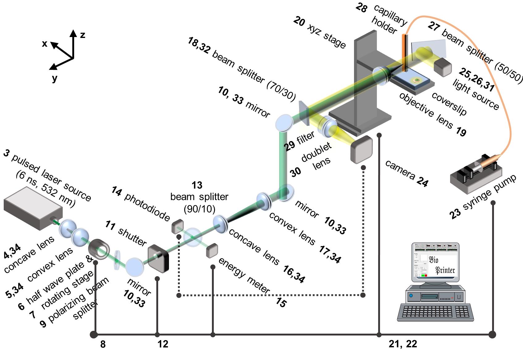
Figure 1. Schematic of laser-induced side transfer (LIST). The numbering of the items corresponds to that of the Equipment section.
Software
MATLAB 2020a (MathWorks, https://www.mathworks.com/)
Procedure
Neurons harvesting and dissociation
Notes:
This procedure is used exclusively for the extraction of mouse dorsal root ganglions.
Steps 4–18 should be performed in a tissue culture hood.
Anesthetize the mouse with isoflurane (2.5%–3%) and proceed to its euthanasia by decapitation using a scissor.
Turn the mouse to the ventral side and dissect the vertebral column. See Perner and Sokol (2021) for a detailed video.
Using a stereomicroscope, harvest all the dorsal root ganglia to a 15 mL Falcon tube filled with 10 mL of ice-cold supplemented DMEM.
Centrifuge (200 × g, 5 min, room temperature) and remove the supernatant.
Add 1 mL of the prepared solution of collagenase/dispase II and incubate the cell suspension (80 min, 37 °C, mix gently every 20 min).
During the incubation, prepare the BSA gradient by first adding 2 mL of sterile PBS to a 15 mL Falcon tube and then 1 mL of 15% BSA on top dropwise.
During the incubation, prepare the glass pipettes for trituration by heating them on a flame until reaching the following diameters: first pipette: 0.8 mm; second pipette: 0.3 mm; third pipette: 0.15 mm.
Centrifuge (200 × g, 5 min) the tube containing the cells and the collagenase/dispase II solution and gently remove the supernatant using a 1 mL pipette.
Add 10 mL of supplemented DMEM (room temperature) and centrifuge (200 × g, 5 min)
Add 1 mL of supplemented DMEM and 25 μL of DNase.
Using a pipette gun, triturate the cell solution by aspirating and ejecting slowly the DRG neurons in solution 15 times up and down for each pipette size, starting with the larger. Avoid bubbling by ejecting the solution into the wall of the tube.
Pipette the triturated ganglia suspension on the side of the tube with the BSA gradient.
Centrifuge (200 × g, 12 min, room temperature) the neuron-containing BSA gradient.
Note: Set the acceleration and deceleration of the centrifuge to the minimum speed.
After centrifugation, the neurons will be at the bottom of the tube, while the cell debris will be in the BSA gradient.
Gently remove all the supernatant using a P1000 pipette, starting with the debris.
Resuspend the cells in 500 µL of supplemented neurobasal with growth factors and AraC.
Filter the suspension with a 100 µm filter to remove the remaining cell debris, washing the filter with 1 mL of supplemented neurobasal medium.
Count round cell bodies that are approximately 10 µm in diameter using a hemocytometer. You should get >40,000–60,000 cell bodies per one adult mouse.
Centrifuge the cells and resuspend in the bio-ink keeping a concentration of approximately 106 DRG neurons per milliliter.
Bio-ink preparation
Note: The concentration of the cells in the bio-ink can be adjusted to accommodate the desired number of cells per deposited drop. Bio-ink preparation is performed under sterile conditions.
For 40,000 DRG neurons, resuspend in 20 µL of supplemented neurobasal with growth factors (NGF, GDNF) and AraC, add 16 µL of fibrinogen 5 mg/mL (final concentration 2 mg/mL), and 4 µL of Allura red AC (laser absorber) 100 mM (final concentration 10 mM).
Pipette the bio-ink to uniformly distribute the cells.
Printing substrate preparation
Note: Printing substrate preparation is performed under sterile conditions.
Dissolve 5 mg/mL of fibrinogen from bovine plasma in warm basal medium at 37 °C.
Shake very gently by hand until the fibrinogen is dissolved.
Filter the solution (0.45 µm filter).
Place a round cover glass on a microscope slide. Place the assembly in a 60 mm Petri dish.
Spread uniformly 5 µL of thrombin (final concentration 4.8 U/mL) on the round cover glass.
Spread uniformly 100 µL of fibrinogen solution on the thrombin-coated cover glass.
Note: Spreading the solution on a 13 mm disk will result in an approximately 0.75 mm thick fibrin layer.
Keep the samples at room temperature for 20–25 min to allow gelation.
Prepare the laser setup for bio-printing
Wear protective laser goggles.
Turn on the laser and set the repetition rate to 20 Hz and the energy to approximately 85% of its maximum power.
Rotate the half-wave plate to adjust the power of the laser beam so that it is clearly visible on the laser viewing card.
Use the viewing card to verify that the laser beam passes through the central part of the optical elements of the setup (i.e., indicated with numbers 4, 5, 6, 7, 9, 10, 11, 13, 14, 15, 16, 17, 18 and in Figure 1).
If the setup is misaligned, proceed with laser alignment correction maneuvers. This step requires prior experience on laser alignment. Basic instructions can be found here: https://www.youtube.com/watch?v=qzxILY6nOmA
Measure the laser energy at the sample level by placing the pyroelectric sensor after the objective lens.
Note: Ensure that the beam covers at least 80% of the sensor. To avoid any damage to the sensor, do not place it at the focal point of the objective lens or close to it.
Measure the laser energy of the sampled beam (see element 15 in Figure 1).
Use the measurements obtained in steps 6 and 7 to calculate a correlation coefficient between the sampled laser beam energy and laser beam energy at the sample (capillary). You may assume this correlation coefficient constant for a single experimental session.
Capillary positioning and alignment
Connect the glass square capillary to the tube and secure it at the holder using the O-ring (Figure 2a).
Position the capillary in front of the objective (Figure 2b).
Use the translation stage and the camera to position the capillary at the focal point of the imaging system.
Fine tune the position of the capillary to focus on its front outer wall (i.e., the side facing the objective lens).
Note: The imaging and laser focusing components of the setup shown in Figure 1 must be set to confocality.
Identify the laser spot in the camera view (Figure 2c).
Adjust the position of the capillary holder in the y and z axes so that the laser spot is located 500 μm far from the capillary distal end and at the center of the capillary wall.
Displace the capillary 300 μm in the x axis towards the objective lens.
Note: After completing steps 4–7, the focal point of the laser beam is set at the center of the capillary and at 500 μm from its distal end (Figure 2d).
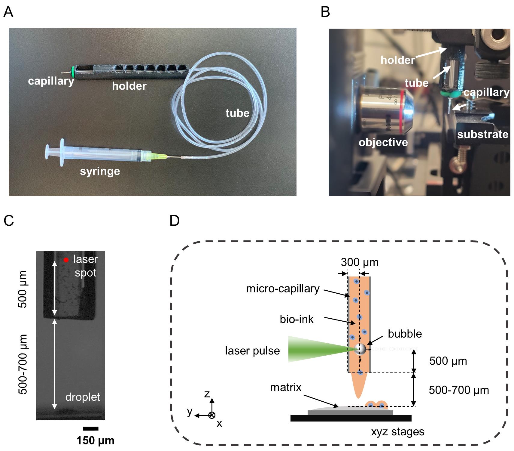
Figure 2. Overview of capillary filling, positioning, and alignment procedures. (A) Picture showing a capillary mounted on a capillary holder and connected to a syringe via a tube. (B) Picture showing the placement of the capillary in reference to the objective. (C) Side view of the capillary and substrate. (D) Schematic showing the desired alignment of the capillary in reference to the laser beam.
Printing protocol
Turn on the laser, the computer, the syringe pump, the mechanical shutter, and the translation stage controller.
Run the laser at 20 Hz repetition rate at >90% of its maximum power for at least 5 min.
Considering the correlation coefficient (see step 8 in section D), set the laser energy to 120 μJ at the sample level (capillary) by rotating the half wave plate.
Run the MATLAB algorithm that controls the different components of the bioprinting setup (see Supplementary material 2).
Use the graphical user interface (GUI) to
Set the shutter opening time to 50 ms.
Set the speed and acceleration of the translation stage to 10 mm/s and 5 mm/s2, respectively.
Define a printing pattern (e.g., an array of individual droplets separated by a 500 μm gap).
Load approximately 40–100 μL of freshly prepared bio-ink (see section B) to the tube using a pipette (Figure 3a).
Connect the tube to a syringe pump (Figure 3b) and pump gently to move the bio-ink up to the capillary distal end.
Stop the pump when the bio-ink level has reached the distal end of the capillary.
Note: This step requires some practice to avoid overflow because the bio-ink advances rapidly once transitioning from the tube to the capillary.
Place the cover glass containing the printing substrate on the XYZ translation stage (see Figure 4).
Use the sample translation stage to set the distance between the capillary tip and the top of the gel at 500–700 μm (see Figure 4).
Run the GUI to start the printing.
Videos 1 and 2 show the LIST bioprinter setup and the bioprinting process.
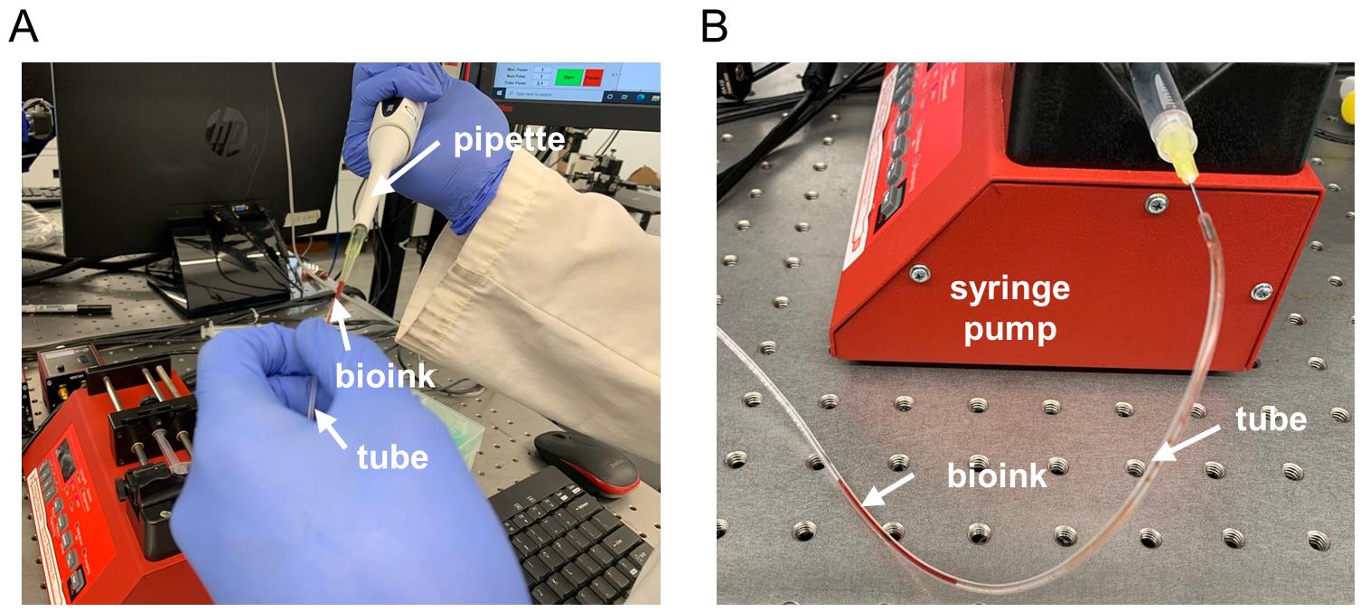
Figure 3. Bio-ink loading steps (A) Injection of the bio-ink to the tube and (B) connection to a syringe pump.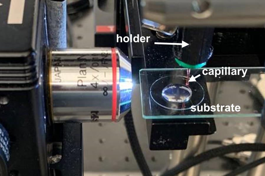
Figure 4. Close-up photo of a ready-to-print experimental setup. Video 1. The LIFT bioprinting setup. Video 2. The LIFT bioprinting process.
Once the printing process is completed, remove the capillary holder, capillary, and tubing.
Rinse the tube and capillary with 70% ethanol (approximately 6 mL) and water (approximately 6 mL) and dry them with filtered compressed air.
Store the capillary and tube in a sterile environment.
Post printing processing
Place the cover glass on a 12-well plate and place in an incubator for 20 min.
Rinse the cover glass twice with 1 mL of pre-warmed (37 °C) neurobasal medium.
Add 2 mL of supplemented neurobasal with growth factors and AraC (37 °C) and put back in the incubator for 48 h.
Use a microscope to observe the samples and to verify successful printing of individual DRG-containing drops (see Figure 5).
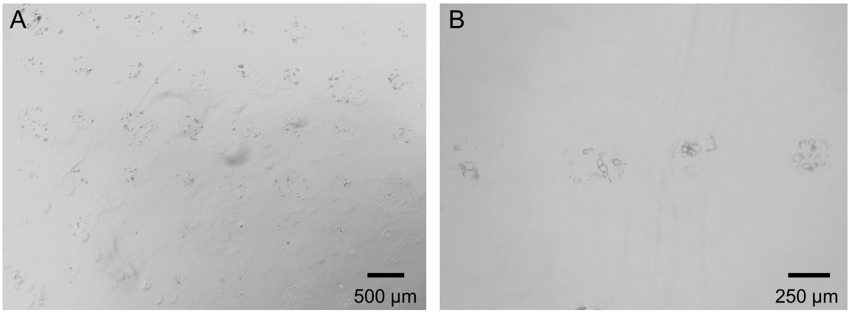
Figure 5. Low (A) and high (B) magnification microscopy images of printed droplets containing DRG neurons (1 h after printing).Calcium imaging in printed DRG neurons
Calcium influx imaging can be used to test DRG neurons for responsiveness to ligands of ion channel receptors.
Print dissociated DRG neurons from TRPV1cre::GCaMP6ffl/wt mice [using the methodology described above, mice were generated by crossing homozygote lox-stop-lox-GCaMP6f (GCaMP6ffl/fl;) with TRPV1cre].
After 48 h in culture, transfer the coverslips containing the printed neurons to a 35 mm glass bottom dish.
Wash the cells three times with 1 mL of standard extracellular solution (SES, 145 mM NaCl, 5 mM KCl, 2 mM CaCl2, 1 mM MgCl2, 10 mM glucose, 10 mM HEPES, pH 7.5).
Keep the cells in 2 mL of SES.
Transfer the dish to a microscope.
Identify a neuron-containing drop and record the baseline fluorescence intensity (GFP channel) (see Figure 6a).
Using barrels, flow (30 s) a solution of 1 µM capsaicin (TRPV1 channel agonist) and wash (210 s) with SES (see Figure 6b for typical response).
Flow (30 s) a solution of 50 mM KCl (positive control) and wash (210 s) with SES.
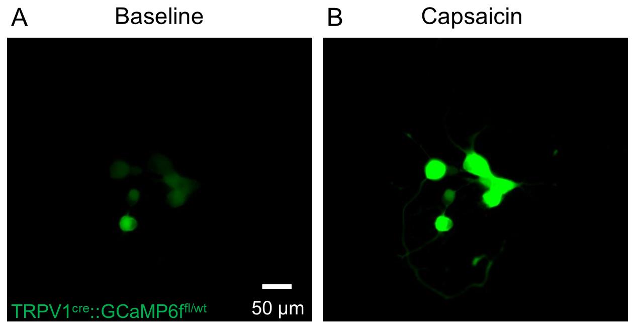
Figure 6. Representative imaging of calcium influx in printed DRG neurons from TRPV1cre::GCaMP6ffl/wt mice (A) before and (B) after exposure to capsaicin (1 μM; 30 s).
Notes
The cell type and density, as well as the type and concentration of the biological active components of the bio-ink, can affect the printing process. LIST printing of bio-ink compositions different from the one used in this protocol may require additional investigation to determine the optimal printing energy (120 μJ for the bio-ink composition used here). Printing of high viscosity bio-inks will require higher energy. One should experiment by gradually increasing the energy until printing is achieved.
Creating bubbles in the capillary requires sufficient absorption of the laser energy by the bio-ink. For this purpose, a food dye (Allura Red AC) is added to the bio-ink before printing. The dye absorbs the laser energy resulting in cavitation. After printing, the food dye is rinsed. Yet, cells are exposed to the dye, and this is one of the limitations of LIST. One should always verify that the dye is not cytotoxic if a new cell type is used. Alternative dyes or light-absorbing additives can be used to replace Allura Red AC if they present strong absorption at 532 nm. The optimal printing energy will decrease with the increase of the absorption coefficient of those materials.
Before loading the cell in the tube, this must be inspected for residual liquid drops. Those drops cause discontinuity in the bio-ink flow and thus irregular printing.
In the capillary alignment process, one should image its front wall (i.e., the wall facing the objective lens). This is a quite challenging step. One can add a mark at the front wall of the capillary using a pen to facilitate focusing.
With time, cells tend to accumulate in the capillary opening due to gravity. This causes non-uniform distribution of cells in the printed pattern. To mitigate this effect, use the pump to apply a few withdraw/infuse cycles to mix the bio-ink.
Recipes
Supplemented DMEM
Sterile DMEM supplemented with FB essence (10%), penicillin (100 I.U.), and streptomycin (100 µg/mL). Store at 4 °C for up to one week.
Collagenase/dispase II
Sterile PBS supplemented with collagenase A (1 mg/mL) and dispase II (2.4 U/mL). Aliquot and store at -20 °C for up to three months.
BSA 15%
Dilute BSA in sterile PBS to a final concentration of 15%. Store 1 mL aliquots at -20 °C for up to six months.
Supplemented neurobasal
Sterile neurobasal supplemented with penicillin (100 I.U.), streptomycin (100 µg/mL), XenoFree B-27TM (1×), and L-glutamine (200 μM). Store at 4 °C for up to two weeks.
Supplemented neurobasal with growth factors and AraC
Add NGF (50 ng/mL), GDNF (2 ng/mL) and AraC (10 μM) to supplemented neurobasal (recipe 4). Prepare fresh.
Acknowledgments
This research was funded by the Natural Sciences and Engineering Research Council of Canada (Discovery grant RGPIN-2018-06767; CB), the Canadian Foundation for Innovation (ST, #37439), and the Canada Research Chair program (ST, #950-231859). CB is the recipient of a Junior II salary award from the Fonds de la Recherche en Santé du Québec (#312263). KR holds postdoctoral fellowships from the Fonds de Recherche du Québec Nature et technologies (FRQNT), the Fonds de recherche en ophtalmologie de l’Université de Montréal and the Centre Interdisciplinaire de Rcherche sur le Cerveau et L’apprentissage (CIRCA). HEO was the recipient of a PhD scholarship from the FRQNT. This protocol is derived from two recent publications from our group (Ebrahimi Orimi et al., 2020; Roversi et al., 2021).
Competing interests
The authors declare no conflict of interest.
Ethics
The Institutional Animal Care and Use Committees of Université de Montréal (CDEA #22-054, #22-053) approved all animal procedures.
References
- Ebrahimi Orimi, H., Hosseini Kolkooh, S. S., Hooker, E., Narayanswamy, S., Larrivee, B. and Boutopoulos, C. (2020). Drop-on-demand cell bioprinting via Laser Induced Side Transfer (LIST). Sci Rep 10(1): 9730.
- Kang, H. W., Lee, S. J., Ko, I. K., Kengla, C., Yoo, J. J. and Atala, A. (2016). A 3D bioprinting system to produce human-scale tissue constructs with structural integrity. Nat Biotechnol 34(3): 312-319.
- Knowlton, S., Anand, S., Shah, T. and Tasoglu, S. (2018). Bioprinting for Neural Tissue Engineering. Trends Neurosci 41(1): 31-46.
- Perner, C. and Sokol, C. L. (2021). Protocol for dissection and culture of murine dorsal root ganglia neurons to study neuropeptide release. STAR Protoc 2(1): 100333.
- Roversi, K., Ebrahimi Orimi, H., Falchetti, M., Lummertz da Rocha, E., Talbot, S. and Boutopoulos, C. (2021). Bioprinting of Adult Dorsal Root Ganglion (DRG) Neurons Using Laser-Induced Side Transfer (LIST). Micromachines (Basel) 12(8).
Article Information
Copyright
© 2022 The Authors; exclusive licensee Bio-protocol LLC.
How to cite
Roversi, K., Ebrahimi Orimi, H., Erfanian, M., Talbot, S. and Boutopoulos, C. (2022). LIST: A Newly Developed Laser-assisted Cell Bioprinting Technology. Bio-protocol 12(19): e4527. DOI: 10.21769/BioProtoc.4527.
Category
Biological Engineering > Bioprinting
Biological Engineering > Biomedical engineering > Drug Delivery
Biological Sciences > Biological techniques
Do you have any questions about this protocol?
Post your question to gather feedback from the community. We will also invite the authors of this article to respond.