Advanced Search
Design of Extended Field of View Light Field Microscopy for Whole Brain Functional Imaging in Larval Zebrafish
Last updated date: Aug 20, 2020 Views: 1411 Forks: 0
Design of lenslet array
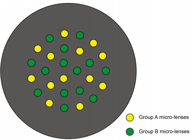
The customized lenslet array is an aluminum plate (2.3 mm thick) with 27 holes (2 mm deep, 1.3 mm diameter aperture on one side and 1 mm diameter aperture on the other side) housing 27 customized micro-lenses. The 27 micro-lenses (1.3 mm diameter, 3 mm thick, focal length: 24.6 mm or 26 mm) were divided into two groups (Figure 1) to cover a larger axial range.

Figure 1. Two groups of micro-lenses in lenslet array.
Alignment of XLFM system
1. Prepare a collimated 488 nm laser beam for alignment.
2. Direct the collimated alignment laser beam into the imaging objective (Olympus, XLPLN25XWMP2, 25X, NA1.05, WD 2 mm) from the imaging side. Adjust the beam to make it normal incidence with respect to the flat glass surface of the objective.
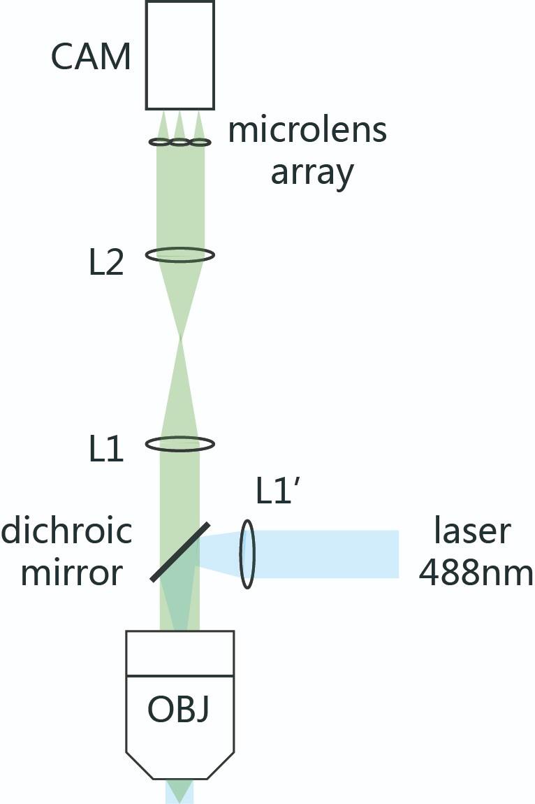
3. Place an achromatic lens (L1, focal length = 180 mm, Figure 2) after the objective, and adjust the distance between the achromatic lens and the objective to make output beam after L1 collimated. In this way, the L1’s focal plane is aligned with the back focal plane of the objective.
4. Place another achromatic lens (L2, focal length = 160 mm, Figure 2) after L1 to form an optical 4f system so that the objective back focal plane could be conjugated to L2 back focal plane.
5. Put the lenslet array on the back focal plane of L2.
6. Place a sCMOS camera (Hamamatsu, Orca-Flash 4.0 v2) on a precise three-dimensional moving stage and align it to the middle plane between two focal planes formed by two groups of micro-lenses on the lenslet array.
7. Introduce the excitation laser (Coherent OBIS 488 nm) into the system by inserting a dichroic mirror (Semrock Di02-R488-25x36) between the achromatic lens (L1) and the objective.
8. The excitation laser is expanded into a collimated beam of diameter of 25 mm and then focused into the back focal plane of the objective by an additional achromatic lens L1’ (focal length = 125 mm, Figure 2). Adjusting the position of the L1’ to make sure the excitation laser beam is collimated when exiting the objective.
9. Fine align the whole system and shade the entire light path.

Figure 2. Schematic of XLFM system. L1, L2, L1’: achromatic lenses; CAM: camera; OBJ: objective
Measurement of point spread function (PSF) and magnification between two groups of micro-lenses
1. Drop the diluted beads (ThermoFisher F8888) solution on a piece of cover glass and dry in the air.
2. Put the cover glass on a three-dimensional moving stage.
3. Select an imaging field of view (FOV) with only one bead in the center of FOV.
4. Find the focal planes of two groups of micro-lenses and define the position of their midpoint as the focal plane of XLFM.
5. Get a stack of image of the bead at the center of FOV from 200 μm beneath the focal plane of XLFM to 200 μm above the focal plane with a step of 2 μm.
6. Change to a FOV with more than one bead and measure the distance of each two beads in each sub-image.
7. Calculate the ratio between two magnifications of two groups of micro-lenses as
Animal handling
1. For restrained experiments, 4–6 dpf zebrafish were embedded in 1% low melting point agarose.
2. For freely moving experiments, 7–11 dpf zebrafish with 10% Hank’s solution were transferred to a customized chamber (20 mm in diameter, 0.8 mm in depth), and 10–20 paramecia were added before the chamber was covered by a coverslip. Zebrafish were habituated in the chamber for 20 minutes before imaging.
Image reconstruction of XLFM
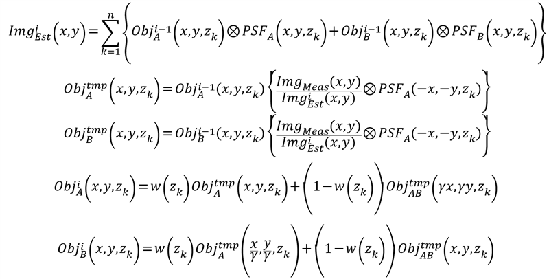
The reconstruction algorithm was derived from the Richardson-Lucy deconvolution. The goal of the algorithm is to estimate the from the measured camera frame:
1. The images formed by two different groups of micro-lenses had different magnifications, which could be determined experimentally. The ratio between two different magnifications can be defined as:
2. Then, the captured image on the camera can be estimated as:
The operator ⨂ represents 2D convolution.
3. According to the Richardson-Lucy deconvolution algorithm, the iterative reconstruction can be expressed as:
4. , which means to weigh information from two groups of micro-lenses equally.
5. The reconstruction algorithm was typically terminated after 30 iterations when modifications in the estimated object became very small.
The source code written in MATLAB can be found in the Source code file 2.
- CONG, L, Bai, L and Wang, K(2020). Design of Extended Field of View Light Field Microscopy for Whole Brain Functional Imaging in Larval Zebrafish. Bio-protocol Preprint. bio-protocol.org/prep457.
- Cong, L., Wang, Z., Chai, Y., Hang, W., Shang, C., Yang, W., Bai, L., Du, J., Wang, K. and Wen, Q.(2017). Rapid whole brain imaging of neural activity in freely behaving larval zebrafish (Danio rerio). eLife. DOI: 10.7554/eLife.28158
Category
Do you have any questions about this protocol?
Post your question to gather feedback from the community. We will also invite the authors of this article to respond.
Share
Bluesky
X
Copy link


