

Imaging Single-Cell Ca2+ Dynamics of Brainstem Neurons and Glia in Freely Behaving Mice
自由行为小鼠脑干神经元和胶质细胞的单细胞Ca2+动态成像
发布: 2024年04月20日第14卷第8期 DOI: 10.21769/BioProtoc.4973 浏览次数: 2828
评审: Bo LiangYueqing PengAnonymous reviewer(s)
参见作者原研究论文
The authors used this protocol in:

Oct 2022
Advertisement


Abstract
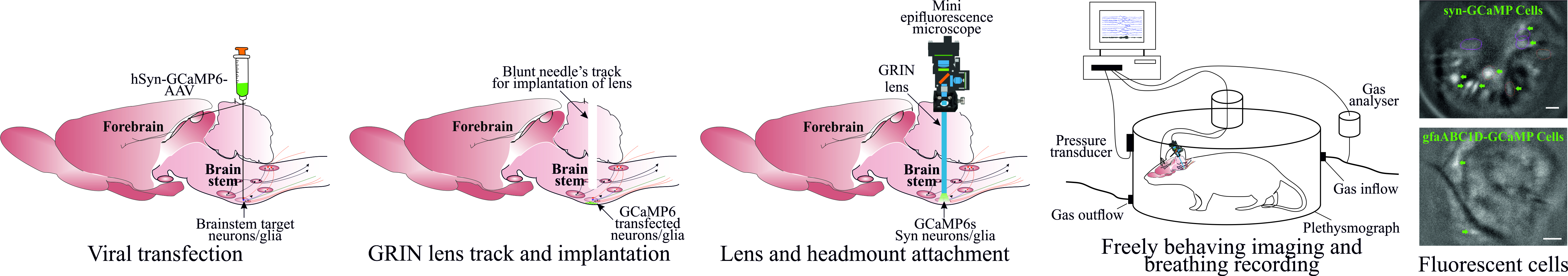
In vivo brain imaging, using a combination of genetically encoded Ca2+ indicators and gradient refractive index (GRIN) lens, is a transformative technology that has become an increasingly potent research tool over the last decade. It allows direct visualisation of the dynamic cellular activity of deep brain neurons and glia in conscious animals and avoids the effect of anaesthesia on the network. This technique provides a step change in brain imaging where fibre photometry combines the whole ensemble of cellular activity, and multiphoton microscopy is limited to imaging superficial brain structures either under anaesthesia or in head-restrained conditions. We have refined the intravital imaging technique to image deep brain nuclei in the ventral medulla oblongata, one of the most difficult brain structures to image due to the movement of brainstem structures outside the cranial cavity during free behaviour (head and neck movement), whose targeting requires GRIN lens insertion through the cerebellum—a key structure for balance and movement. Our protocol refines the implantation method of GRIN lenses, giving the best possible approach to image deep extracranial brainstem structures in awake rodents with improved cell rejection/acceptance criteria during analysis. We have recently reported this method for imaging the activity of retrotrapezoid nucleus and raphe neurons to outline their chemosensitive characteristics. This revised method paves the way to image challenging brainstem structures to investigate their role in complex behaviours such as breathing, circulation, sleep, digestion, and swallowing, and could be extended to image and study the role of cerebellum in balance, movement, motor learning, and beyond.
Key features
• We developed a protocol that allows imaging from brainstem neurons and glia in freely behaving rodents.
• Our refined method of GRIN lenses implantation and cell sorting approach gives the highest number of cells with the least postoperative complications.
• The revised deep brainstem imaging method paves way to understand complex behaviours such as cardiorespiratory regulation, sleep, swallowing, and digestion.
• Our protocol can be implemented to image cerebellar structures to understand their role in key functions such as balance, movement, motor learning, and more.
Graphical overview
Background
In vivo Ca2+ imaging of neurons and glia in freely behaving rodents offers an exciting opportunity to understand brain structures with cellular resolution of their function, something that cannot be gained with any other current methodologies. Over the last decade, since the invention of the first intravital microscope [1], a tremendous advance has been made in the field with wireless cameras [2], dual colour imaging, large-field imaging [3], geometric transformation adaptive optics [4], imaging combined with optogenetics [5], improved fluorescent Ca2+ indicators [6], use of cre-dependent GCaMP reporter mice [7,8], and intersectional genetics to target subpopulations of cells of interest [9]. However, one of the major challenges remaining in the field is to record reliably from hard-to-access and potentially mobile brain regions such as the brainstem and cerebellum.
We have recently published our studies targeting neurons from the ventral brainstem surface called the retrotrapezoid nucleus (RTN) and medullary raphe to investigate their role in central chemosensitivity [10] and investigate the effect of acute and chronic seizures on the RTN neurons [11]. Our refined surgical protocol provides a way to record brainstem neurons and glia with cell analysis and selection/rejection criteria to identify the cells of interest. Although there are surgical protocols for imaging neurons and glia from the forebrain [12] and rostral brainstem [13], these protocols cannot be directly applied for brainstem imaging due to: i) gradient refractive index (GRIN) lens implantation/insertion through cerebellar and brainstem regions and associated risk of damage to basic/vital life functions and ii) additional complexity of motion artefact due to movement of brainstem tissue outside the cranial cavity. Our protocol specifically deals with these issues by creating a guide track for lens insertion and implantation and rejecting cells displaying artefactual activity correlated with body movements. Despite the improved ways to image brainstem neurons and glia in freely behaving rodents, we might be limited to targeting the rostral brainstem region. Imaging from the most caudal brainstem nuclei would require implantation of lenses through, and baseplate attachment over, the occipital bone (at the posterior end of interparietal bone), which is angled and densely innervated with muscles. Whilst our improved methodology increases the duration of lens implantation surgeries, it allows for the best surgical outcomes with the least postsurgical complications.
Overall, our improved surgical and cell analysis and selection protocol paves the way to image and record the activity of brainstem structures, to investigate their role in previously studied complex behaviours such as breathing [14,15], circulation [15,16], sleeping [17], digestion [18], and swallowing [19]. It could be extended to study the role of glial cells in numerous neurological disorders [20,21] and cerebellar structures in balance, movement, motor learning [22], and many other.
Materials and reagents
Biological materials
AAV-9:pGP-AAV-syn-GCaMP6s-WPRE.4.641 (Vigene Biosciences, SKU BS1-NOSAAV9: USA)
AAV-5: pZac2.1 gfaABC1D-cyto-GCaMP6f (Addgene, 52925, USA)
C57BL/6 mice (Charles River: UK)
Reagents
Isoflurane (Piramal Critical Care, catalog number: 2800025)
Atropine (Macarthys Laboratories Ltd., catalog number: PL01883/616R)
Meloxicam (Boehringer Ingelheim, catalog number: Vm 04491/5025)
Buprenorphine (Reckitt Benckiser, catalog number: Vm 15052/4081)
Superbond Universal Kit (Sun Medical Co., catalog number: K058E)
PVA glue (Hobbycraft Trading Ltd., catalog number: 5672751000) or silicon adhesive (WPI, catalog number: Kwik-Cast)
Eye ointment (Dr Gerhard Mann, catalog number: MEVIS05)
Lubricating jelly (Thornton & Ross Ltd., catalog number: 24242902)
Vetscrub (NewGenn Ltd., catalog number: CD003)
70% ethanol (VWR Chemicals, catalog number: UN1170)
Sodium chloride (NaCl) (VWR International Ltd., catalog number: 27788.297)
Distilled water
Solutions
Sterile 0.9% saline solution (see Recipes)
Recipes
Sterile 0.9% saline solution
Reagent Final concentration Quantity or Volume NaCl 0.9% 9 g Distilled water n/a Up to 1,000 mL Dissolve 9 g of NaCl in 600 mL of distilled water and make up the final volume to 1 L. Autoclave and sterilise the solution for 15 min at 15 psi and 121 °C.
Laboratory supplies
Nitrile gloves (Starlab International), sterilised by autoclaving
Cotton buds (Dutscher, catalog number: 1504), sterilised by autoclaving
Tissue paper, sterilised by autoclaving
Surgical coat, sterilised by autoclaving
Overhead cap (Pal International Ltd.)
Mask (3M, FFP2)
Scalpel blades (Swann Morton Ltd., catalog number: BS2982)
Capillary tubes (Drummond Scientific Company, catalog number: 2-000-001)
Double-edged blade (Scientific Laboratory Supplies Ltd., catalog number: BH10)
Superglue (RS Components Ltd., catalog number: 473-455)
Blunt needles, 24 gauge (Becton Dickinson, catalog number: MIC0067)
Eppendorf 0.2 mL PCR tube cap (Eppendorf, catalog number: 0030124332)
Silicone tubing with syringe for viral injection (Saint-Gobain Life Sciences, catalog number: E-3603)
Aldasorber (Aston Pharma, catalog number: AST501)
Aluminium foil
Cling film
Equipment
nVista epifluorescent imaging system/camera (Inscopix, model: nVista)
Baseplate holder (Inscopix)
Miniscope system with DAC box (Inscopix)
ProViewTM GRIN lens probe 0.6 mm diameter, ~7.3 mm length (Inscopix, catalog number: 1050-002208)
Baseplates (Inscopix, catalog number: 1050-002192)
Baseplate cover (Inscopix, catalog number: 1050-002193)
Surgical tools (Fine Science Tools)
Lens holder (Inscopix, catalog number: 1000-004238)
Stereotaxic apparatus with electrode holder (Kopf, model: 940)
Trimmer
Anaesthetic machine with induction chamber (VetTech Solutions Ltd., catalog number: AN003-K)
Capillary puller (Sutter Instrument Co., model: P-97)
Heating pad (Dreamland)
Thermocouple heating system (Physitemp Instruments Inc., catalog number: TCAT-2LV)
Drilling machine with bits (Foredom, catalog number: SKU K.1070-21)
Plethysmography chamber (custom-made 0.5 L Plexi glass with air inlet and outlet)
Gas analyser (Hitech Instruments, model: GIR250)
NeuroLog system (Digitimer, model: NL900D)
Microinjection system: custom-made by connecting a graduated glass pipette to silicon tubing, which was attached to a 1 mL syringe on the other end. Pressure was manually controlled in the tubing with the syringe to achieve desired injection speed
Surgical microscope
Software and datasets
Inscopix Data Processing Software (IDPS) (Version 1.6.0.3225)
Inscopix Data Acquisition Software (version 2.0)
Spike2 (Version 8.23)
ANY-maze video tracking software (ANY-maze: Ireland)
Procedure
Below, we describe the surgical protocol for viral transfection (this step is optional if using the cre-dependent GCaMP reporter mice), implantation of GRIN lens, and baseplate installation. This is followed by the procedure for Ca2+ imaging in freely moving mice and data analysis.
Presurgical calibration
Calculate and validate the injection coordinates before viral injection, using fluorescent bead or dye injections to confirm coordinates for both viral injection and implantation of the lens.
Calculate the viral titre by injecting different concentrations of virus and imaging the GCaMP expression.
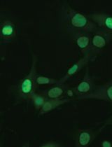
Ideally, cell somata should express the GCaMP without much expression in nuclei (Figure 1). This is critical to make sure viral titre is not too low (as it will not give a sufficient signal) nor too high (as it will compromise neuronal activity and health) during core recording experiments.
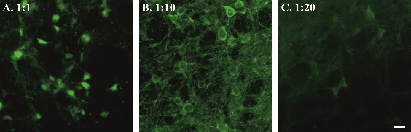
Figure 1. Viral titre and GCaMP expression. Examples of high (A), moderate (B), and low (C) syn-GCaMP expressing cells. Scale bar, 20 μm.
Presurgical preparation for aseptic surgery
Autoclave all surgical tools, drapes, cotton buds, foil, and tissue to be used in the surgery.
Drape the equipment and area used for storing all surgical tools and sterile consumables with autoclaved surgical drapes.
Cover all the surfaces that will be handled/touched during surgery with sterile aluminium foil or cling film i.e., microscope head and bar, stereotaxic frame knobs, etc.
Viral transfection
Initial animal surgical preparation.
Check and report the weight of the animal before surgery. Ideally, adult male or female mice between 8 and 12 weeks old are used.
Place the animal in the anaesthesia induction chamber (connected to the scavenger) with 4% isoflurane balanced with oxygen (4 L/min).
Once the animal is anesthetised, transfer it over to the stereotaxic apparatus. Place the animal prone onto the stereotax, put teeth into bite bar, and connect to the isoflurane nosecone to maintain anaesthesia throughout the surgery [0.5%–2% isoflurane in pure oxygen (1 L/min)].
Give a presurgical subcutaneous injection of atropine (120 μg/kg) and meloxicam (2 mg/kg) prepared in sterile 0.9% saline solution. Atropine reduces bronchial secretion and keeps the trachea clear. Meloxicam provides long-term analgesic effects due to its longer half-life (20 h).
Lubricate the thermocouple probe in lubricating jelly, insert it into the animal’s rectum to regulate the body temperature. Body temperature is maintained at ~33 °C to reduce bleeding and improve recovery.
Cover the animal’s eyes with eye ointment to prevent drying and protect from the light.
Fix the animal’s head into the ear bars.
Trim hair over the head. Wet shave the surgical area with a double-sided razor blade, using a cotton swab to apply either 70% ethanol or vetscrub.
Sterilise the surgical area of skin over the head with three alternating scrubs of vetscrub and 70% ethanol: always start with vetscrub as it can cause contact dermatitis if not removed with the ethanol.
The surgeon should dress for aseptic surgery: hair net, facemask, sterile gloves, and autoclaved surgical gown. The surgeon may be aided by a non-sterile assistant throughout the surgery.
Cover the animal in a cling film or sterile drape.
Virus injection.
Make a sagittal incision down the skull of approximately 1–1.5 cm so that bregma and the injection site can be accessed.
Remove all the connective tissues from the top of the skull using a sterile cotton-tip applicator (Figure 2A).
Place an empty capillary into the holder and adjust the skull position so that bregma is level with 2 mm caudal to bregma. We checked the skull’s left-right levelling at 1 mm laterally; ± 40 μm variation is acceptable.
Drill a hole at the stereotaxically designated position from bregma. To target brainstem nuclei, change the stereotaxic arm anteroposterior angle up to approximately 10° to achieve the desired targeted injection. For example, the coordinates for the retrotrapezoid nucleus with a 9° stereotaxic arm anteroposterior angle are -1.0 mm lateral and -5.6 mm caudal from Bregma and -5.5 mm ventral from the surface of the cerebellum (Figure 2B).
Load the capillary with viral solution and place in the capillary holder. Volume of injection depends on the target region. Generally, smaller and tighter injections (50–200 nL) are better for the specificity.
Connect the capillary to plastic tubing connecting to a pressure delivery system, e.g., a 1 mL syringe or a picospritzer.
Place the tip at bregma for calculating coordinates. Move the capillary tip to the desired injection site (keeping in mind the angle of the capillary holder). Lower the capillary into the drill hole.
i. Zero the Z coordinates at the surface of the brain.
ii. Do not keep the capillary touching the brain surface for too long, as this may lead to blockage of the capillary with keratin in the cerebral spinal fluid.
Insert the capillary to the desired Z coordinates.
Gently apply pressure through the system. Make sure to observe the movement of viral solution meniscus in the capillary through the microscope. Adjust the pressure accordingly to inject viral solution at a speed of approximately 100 nL/min (Figure 2C).
Keep the capillary in place for 3–5 min after injection to prevent backflow up the capillary track and to allow time for virus to spread at the tip of capillary.
Gently remove the capillary.
Pull the skin together and seal the wound with tissue adhesive.
Remove the animal from the stereotaxic frame.
Inject buprenorphine intraperitoneally (100 μg/kg prepared in sterile 0.9% saline solution).
Place the animal back in the cage on a heating pad until recovery.
Observe the animal until full recovery and monitor daily for postsurgical recovery for up to two weeks.
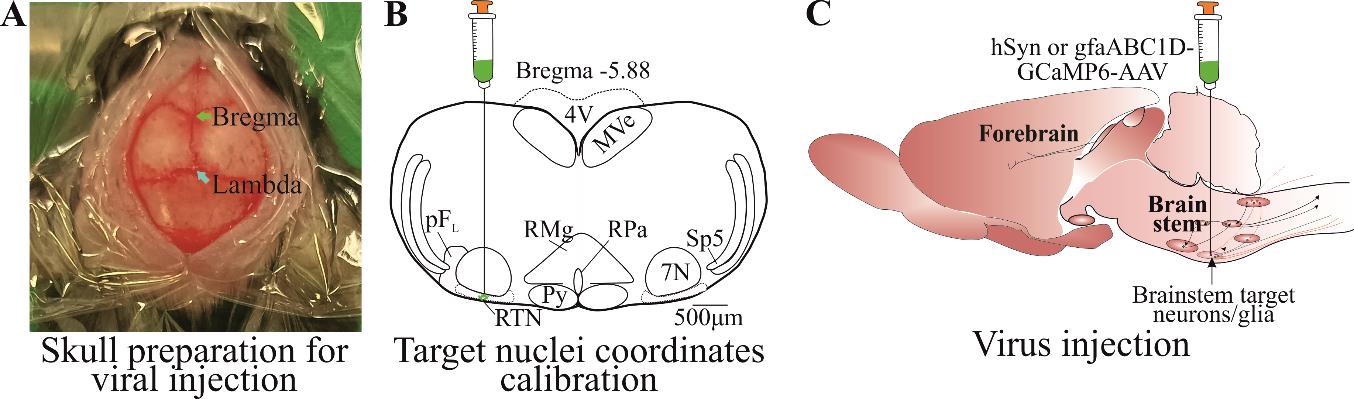
Figure 2. Viral transfection. A) Skin cut and skull top preparation for virus injection by removing connective tissues. B) Calibrated injection coordinates. C) Injection of AAV9-Syn or gfaABC1D-GCaMP6s virus using calibrated coordinates. Abbreviations: 7 N, facial motor nucleus; Py, pyramidal tract; MVe, medial vestibular nucleus; sp5, spinal trigeminal nucleus; RTN, retrotrapezoid nucleus; RMg, raphe magnus; RPa, raphe pallidus; pFL, parafacial lateral region.
GRIN lens implantation
Prepare the animal as for steps B and C1.
After the incision is made, remove an additional 1 mm of tissue from the cut edge (Figure 3A). This creates space for superbond to build around the lens. Using a sterile cotton-tip applicator, remove all the periosteum and connective tissue from the skull’s surface (Figure 3A).
Place an empty capillary into the holder and adjust the skull position so that the bregma is level with 2 mm caudal to bregma and the skull is left-right level at 1 mm laterally; ± 40 μm variation is acceptable.
Drill a hole at the stereotaxically designated position from bregma, big enough for the GRIN lens (Figure 3Be) to pass through (crucial). For our surgery, we used 0.6 mm diameter lens, and a hole size of approximately 0.7 mm was big enough to insert the lens through (the hole should be ~0.1 mm bigger than the lens diameter). The hole size can be checked by aligning the GRIN lens tip against the hole. It is crucial that the hole is not too big as this will not provide skull support to the lens and can allow superbond solution to enter the wound, causing postsurgical complications.
Creating track for the GRIN lens (crucial).
Creating a lens track is a very important and essential step, as insertion of the lens without creating a track applies pressure on the cerebellar and brainstem nuclei and leads to severe postoperative complications.
The lens track is created by inserting an empty capillary (to a depth of ~3/4 of the lens track) from the cranial hole drilled at desired coordinates (Figure 3C).
Place the blunt needle (Figure 3Bf) of an approximately similar diameter to the GRIN lens into the stereotaxic arm holder.
Adjust the coordinates at bregma and move the needle tip over the hole. At this point, move a needle at the edge of the hole, touch its tip on the skull surface, and zero the Z coordinates. Then, move the needle to the desired lens implantation position and lower the needle until it touches the brain surface. Calculate the distance between skull surface and brain tissue.
Touch the needle tip to the brain surface and make Z coordinates zero.
Slowly (250 μm/min) insert the needle into the brain tissue until 250 μm, pull it back to zero, insert again until 250 μm, and place it in position for approximately 3 min. This initial insertion generates the pressure on cerebellum and gives time for the needle edges to cut through the brain tissue.
After 3 min, drive the needle 500 μm ventrally and then retract the needle 250 μm. This creates a 250 μm stepwise needle insertion, which does not create excessive pressure on the brain. Perform the 250-μm insertion-retraction steps continuously.
Stop the needle insertion approximately 300–500 μm above the target region of interest or 100 μm above where the tip of the GRIN lens will be. Keep the needle in place at last insertion for approximately 3 min. Keep in mind that the GRIN lens has a focal plane of approximately 300 ± 100 μm from the bottom surface of the lens [10].
Gently withdraw the needle (Figure 3D).
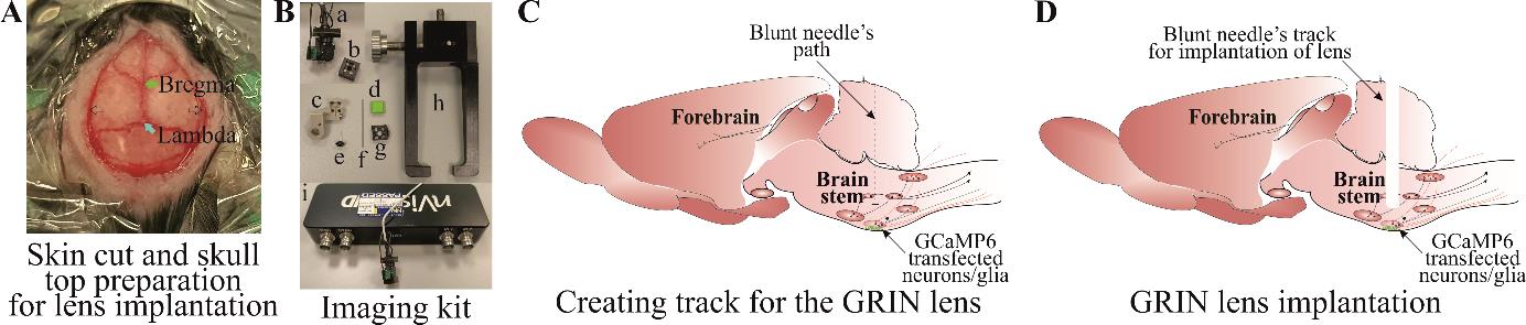
Figure 3. Creating track for the gradient refractive index (GRIN) lens. A) Skin cut and skull top preparation for creating lens track and implantation. B) Imaging kit includes (a) mini epifluorescent camera, (b) microscope objective lens cover, (c) lens holder during surgical implantation, (d) baseplate cover plate, (e) lens, (f) blunt needle, (g) baseplate, (h) baseplate holder for surgical implantation, and (i) DAC box. C) Blunt needle insertion path through the brainstem and D) a track created after removing a blunt needle.Implantation of GRIN lens.
Place the GRIN lens (Figure 3Be) into the holder (Figure 3Bc) attached to the stereotaxic arm and place the camera (Figure 3Ba) into the holder (Figure 3Bc) by removing the camera cap (Figure 3Bb). Adjust the centre of the GRIN lens surface at the bregma.
Move the GRIN lens at the edge of the hole and lower it until it touches the skull surface. Then, move the lens to the desired XY coordinates, lower it down until it touches the brain surface [by a distance between the skull and the brain surface calculated above (2c)], and zero the Z-coordinates.
Slowly insert the GRIN lens using the same insertion-retraction 250 μm steps described in step D2f. Do this until 1 mm depth and wait for 3 min at this point.
From 1 mm onward, drive the lens 200 μm ventrally, then retract it by 100 μm and wait for 1 min before the next insertion.
When the bottom surface of the lens is 500 μm from implantation site (~800 μm from the viral injection site), reduce the insertion speed to 50 μm/step (driving by 100 μm, retracting by 50 μm, and waiting for 1 min) (Figure 4A). Check the GCaMP expression during every insertion step by turning on the camera through the Inscopix Data Acquisition Software and DAC box (Figure 3Bi) so the fluorescence can be seen. Stop the lens insertion when GCaMP expression is good and shows increased whole Ca2+ fluorescence (Figure 4B) compared to low signal (Figure 4C). This should be ~300 μm from the viral injection site. Keep in mind that cellular Ca2+ dynamics are suppressed under anaesthesia and will not be very bright during lens implantation. The purpose of this is to ensure the best possible lens implantation distance from the cells of interest. The lens implantation step may be combined with the viral injection, but performing these as separate surgical procedures ensures the best possible lens implantation and the best possible cellular imaging outcome.
Once the lens is in place, dry the skull surface with Kimwipes or a cotton swab. Mix the superbond polymer with monomer as per the kit’s instruction. Add the catalyst and mix well. Wait until the mixture thickens slightly to a gel-like consistency. Apply the mixture around and at the bottom surface of the lens. This is a very important step. Make sure to avoid application of the mixture to the lens holder (Figure 3Bc) and to keep it away from the animal’s eyes. This first application should cover the lens’s surface around the skull. Wait until the superbond is dry (this takes approximately 10 min; an alternative is to use UV fix superbond, which speeds up the process of solidifying polymer and monomer mixture).
When the superbond is well dried, loosen the lens (Figure 3Be) from the lens holder (Figure 3Bc) and remove it. To do this, loosen the side screw on the holder that securely holds lens into the holder. Make sure that there is no superbond on the joint between lens holder and lens; otherwise, this will move the lens.
Mix the second batch of superbond polymer and monomer. Wait until the mixture is of gel-like consistency, apply it along the skin edges, and build around the lens. Make sure that the superbond does not come above the lens’s top surface (Figure 4D). Wait until the superbond dries.
Cover the lens top surface with an Eppendorf cap cut to the shape and adhere it there with PVA glue (Figure 4D) (alternatively, silicon adhesive can be used to cover the lens top surface) that can be removed during baseplate implantation surgery. This will protect the lens until the baseplate installation.
After the second application of superbond has dried and cap is well sealed to the lens, take off the animal from stereotaxic frame, inject buprenorphine intraperitoneally, and place it back in the cage on a heating pad until recovery.
Watch the animal until full recovery and monitor daily for postsurgical recovery for up to two weeks.
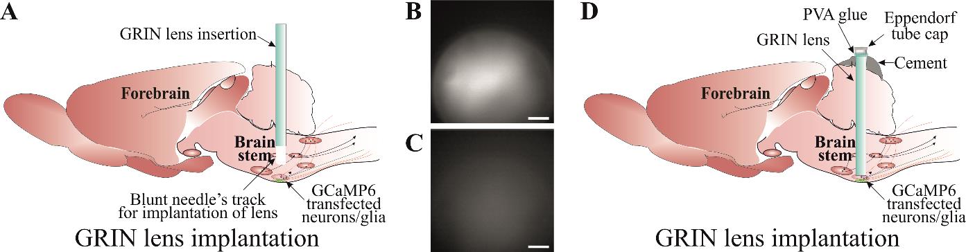
Figure 4. Implantation of gradient refractive index (GRIN) lens. A) Slow insertion of GRIN lens through a track created using a blunt needle until a good GCaMP expression and cellular Ca2+ dynamics are visible. Examples of a good (B) and an inadequate (C) GCaMP expression. D) Securing GRIN lens in a place using a good-quality dental cement. Lens top is covered with an Eppendorf cap cut to the shape and adhered with PVA glue. Scale bar, 50 μm.
Baseplate implantation
The animal will be anesthetised for the baseplate implantation surgery and placed in the stereotaxic frame as per step C1a–g of the viral injection protocol. However, this is a non-invasive surgery and therefore does not require the same sterility protocol as above.
Implanting baseplate.
Peel off the PVA glue to remove the lens cap.
Clean the lens top surface with Kimwipes soaked in ethanol to remove any possible dirt from the surface of the GRIN lens.
Attach the baseplate (Figure 3Bg) to the holder (Figure 3Bh) and place it in position in the stereotaxic arm.
Stereotaxic skull levelling is not possible at this step; therefore, try to level the skull as much as possible.
Attach the camera to the baseplate and move it near the lens surface (Figure 5A). Turn on the recording software and watch the live imaging. Adjust the GRIN lens top surface in the middle of the field of recording and lower the camera slowly until the lens surface is visible (take precautions during this step to not compress the camera lens on to any other surfaces and leave a clear gap between camera and GRIN lens).
When the GRIN lens’ sharp edge is visible (Figure 5B) (at the lowest camera position), adjust the sharpness of all edges by moving the nose cone. This ensures that both the camera and lens surface are parallel to each other.
Move the baseplate position away from the lens at the best possible field of view (Figure 5C). This is generally ~300 μm from the sharp edge. This field of view can be checked by gently touching the animal’s back, which possibly activates the cells to check the Ca2+ signal (Figure 5C).
Viral expression time varies from virus to virus and, therefore, may need extra time for the optimal expression. In this case, the animal can be returned back to the cage (by attaching cap to the lens) and be revisited for the baseplate surgery in a week’s time.
When the baseplate is in position with an optimal GCaMP expression, mix the superbond polymer with monomer and add catalyst to it. When the mixture is of good consistency to form a layer between the side of the baseplate and superbond over the skull, apply it on the edges, making sure it does not run under the baseplate or touches the camera lens. This is a critical step. After the first application, wait until mixture is well dried. Loosen the screw on the baseplate that holds the camera. Retract the camera up and remove it from the stereotaxic holder.
Apply the second layer of superbond to cover and seal all the gaps around the baseplate. If the superbond colour is not dark, then a black nail polish layer can be applied to make it opaque and prevent any light penetration under the baseplate.
Once the baseplate is well fixed, attach the baseplate cover (Figure 3B-d). Take the animal off from the stereotaxic frame and place it back in the cage on a heating pad until recovery.
Watch the animal until full recovery and monitor it daily for at least one week before recordings start.
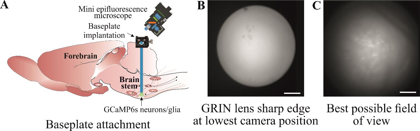
Figure 5. Implantation of baseplate. A) Baseplate is attached to the skull over the gradient refractive index (GRIN) lens so that the best possible cellular Ca2+ dynamics can be imaged. B) The GRIN lens’ sharp edge is visible when the camera is at its lowest position during baseplate implantation. C) Move the baseplate position away from the lens so that the cells can be seen with the best possible field of view. Scale bar, 50 μm.
Mice training
Train the mice with dummy camera in the environment where they will be recorded (Figure 6A). Training could last from 10 to 60 min and depends on the duration of the study protocol. One to three training sessions could be performed at least a day apart.
Ca2+ imaging in freely moving mice
Attach the imaging camera to the animal’s head by docking it in the baseplate and tightening the side screw on the baseplate.
Imaging:
Set the recording parameters as desired to ensure the least LED power to prevent bleaching. Set the optimal recording frame rate [glial Ca2+ transients are slower than neurons, hence can be recorded at slower frame rate (< 10 FPS)] and adjust the plane of focus to achieve the desired field of view for recording (Figure 6C, D). This has been discussed in detail in the previous protocols and can be found in the manufacturer’s manual [12].
Place the animal in the recording environment, e.g., in plethysmographic chamber to test hypercapnic breathing response by measuring changes in breathing tidal volume and frequency (Figure 6B).
Recording should be started depending on the study protocol. The study might require the animal to be settled in the recording environment before recording begins or it might require recording the activity as soon as the animal is placed in the environment. To measure the hypercapnic breathing response from chemosensitive neurons or glia, the animal will be allowed to settle in the plethysmographic chamber connected to a gas analyser (to analyse CO2 and O2) and pressure transducer to measure breathing volume. After the animal is settled, Ca2+ imaging is started [through TTL (Transistor-Transistor Logic) pulse] and baseline breathing recorded followed by hypercapnic challenge and recovery.
The duration of Ca2+ imaging depends on the protocol. However, it is advisable to keep the recording duration as short as possible to avoid fluorophore bleaching. In our study, we have successfully recorded up to 15 min/session from the same mouse multiple times (keeping a week gap between recordings). However, imaging frequency and duration depends on the type of GCaMP indicator and camera imaging settings.
Synchronised video recording:
Real-time animal video can be recorded and synchronised with imaging data using TTL pulse script. Detailed description to set up TTL pulse can be found on CED-Spike2 website. The TTL pulse can be delivered to the DAC box to trigger the Ca2+ imaging, and these can be synchronised during analysis. To start the TTL pulse, a command is given from the Spike software, and this will allow to see when the command was delivered. This command will start the Ca2+ recording and, later, Ca2+ imaging trace is aligned with the TTL pulse command on Spike recording (Spike recording could be EEG or any other feature such as plethysmographic trace).
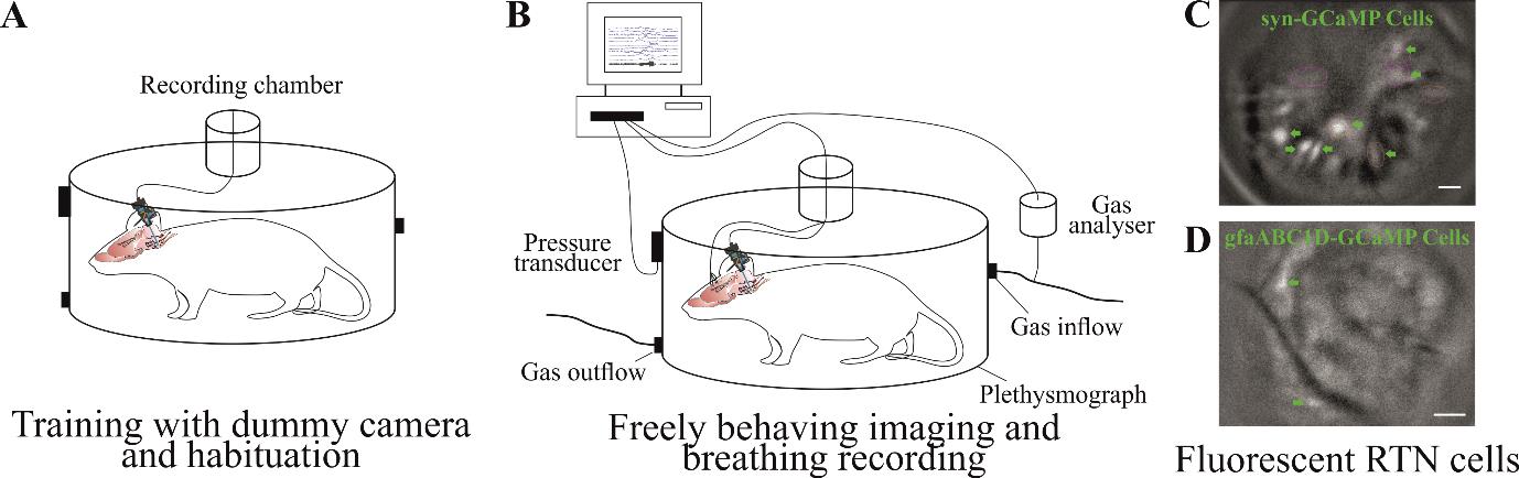
Figure 6. Training and Ca2+ imaging in a freely moving animal. A) Training an animal with dummy camera in an environment where they will be recorded so they get habituated to it. B) Ca2+ imaging of brainstem neurons and glia along with behavioural responses, e.g., breathing reflexes to hypercapnia. Example of fluorescent image from brainstem retrotrapezoid nucleus (RTN) neuronal (C) and astrocytic (D) Ca2+ dynamics. Scale bar, 50 μm.
Data analysis
Data analysis and cell classification
There are multiple ways to process the raw data, e.g., semi-manual ROI analysis, PCA/ICA analysis, constrained non-negative matrix factorisation for microendoscopic data (CNMF-E), and CNMF-E integrated into an open-source package: calcium imaging analysis (CaImAn). All these methods have their merits and demerits, which are outside the scope of this protocol and have been reported previously [23]. We used Inscopix Data Processing Software (IDPS) that incorporates some of these options to analyse imaging data and identify the cells. After the preprocessing step, movements of the visual field that is evident during most recordings was corrected via the Inscopix motion correction software to allow ROI-based measurement of fluorescence to remain in register with the cells during the recording. This allows to correct excessive XY plane movement.
Irrespective of the method used to identify cells, the major challenge with brainstem imaging remains that of the movement artefact. Most of the Ca2+ imaging methods can correct for rigid movement artefacts caused due to the animal or light camera movement. However, brainstem movement is non rigid and cannot be corrected with the previously documented methods that are an inbuild part of the workflow of these analysis methods. Therefore, we designed a cell inclusion/exclusion criterion that allows us to identify and discount/reject the cells caused by artefacts (Figure 7).
After identification of cells using given criteria in specific methods, we aligned all the cells with the video data. We aligned Ca2+ imaging traces with the animal’s body movements in the video recordings using ANY-maze video tracking software and converted these movements into a colour-coded sonogram. Extracted cells were only accepted for categorization if the following criteria were met: (1) The features of the cell (e.g., soma, large processes) could be clearly seen; (2) they occurred in the absence of movement of the animal or were unaffected by animal movement; (3) fluorescence changed relative to the background; and (4) the focal plane had remained constant as shown by other nonfluorescent landmarks (e.g., blood vessels). For the second criterion, cells are not excluded for merely displaying fluorescent changes during body movements. However, calcium signalling should occur irrespective of body movement (except for the motor-related neuronal or glial activity), and when the cells were extracted and aligned with the body movement, the fluorescent changes (amplitude of Ca2+ signal) seen during body movement should not be significantly different from the changes when the animal is quiet.
This method allowed us to include the cells that met the above criteria (Figure 7Aa) and reject cells that are caused by movement artefact, due to the brainstem being in the extracranial space during head, neck, or body movement (Figure 7A-b). This is a very specific issue with brainstem imaging that does not cause a problem while recording from other brain regions, therefore not having been discussed before in other imaging studies.
Previous studies have used anchoring tungsten wires glued to the GRIN lens to stabilise the brainstem imaging field of view [17,24,25]. This additional measure could also possibly help to reduce movement artefact but still does not allow eliminating the changes in cell brightness caused by movement artefact.
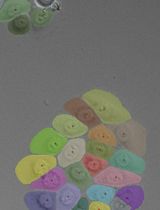
Glial brainstem Ca2+ dynamics are very slow and transient (Figure 7B), which makes it easy to include or exclude these cells using above criteria.

Figure 7. Data analysis and cell classification using set criteria. A) Examples of neuronal GCaMP fluorescence traces that meet (i) and do not meet (ii) our cell inclusion/exclusion criteria to deal with brainstem motion artefact. B) Example of astrocytic GCaMP fluorescence trace. Expanded GCaMP6 signal (3 s) from grey rectangle, presented as a montage of pseudo-coloured fluorescence images, shows slow Ca2+ dynamics in brainstem glia (from no fluorescence at 0 s that peaks in the middle and decays at 3.0 s). Scale bar, 20 μm. Abbreviations: WBP, whole body plethysmography; Mov, movement.
Validation of protocol
This protocol or parts of it has been used and validated in the following research article(s) [10,26]:
Bhandare et al. (2022). Analyzing the brainstem circuits for respiratory chemosensitivity in freely moving mice. eLife (Figures 1–7) [10].
Bhandare et al. (2023). Neural correlate of reduced respiratory chemosensitivity during chronic epilepsy. Frontiers in Cellular Neuroscience (Figures 1, 2, 4, 5 and 7) [26].
General notes and troubleshooting
General notes
Despite this protocol being validated in mice, it could be applicable to rats.
In vivo imaging is technically challenging and, therefore, no single step is crucial; instead, all steps in this protocol are important and must be carefully attended. Optimisation of all steps contributes to successful imaging.
Before starting this protocol, it is very important to validate the brain coordinates for the target nuclei and also the optimal concentration of the virus.
Intravital microscopy imaging generates a large volume of data (in gigabytes, therefore requiring big storage space) and also requires high-performance computers (high CPU speed, large amounts of RAM) to process the data.
It is essential to consider the animal husbandry and housing after implanting GRIN lens and baseplate as the headmount might get stuck into the food hopper or co-housing could damage it.
The choice of GCaMP indicator is important; it is essential to consider the firing properties of the cells and the questions that need to be answered before the start of the study [27].
The re-use of baseplates is very much possible; however, the re-use of the GRIN lens depends on the quality of the lens after its recovery from the previous experiment. Both the baseplate and lens can be left in acetone overnight and gently cleaned the next day using a soft brush.
Troubleshooting
Problem 1: Excessive movement in the imaging that does not look biological.
Possible cause: Biological movement in the imaging sessions is caused by the neck movement where tissue underneath the lens surface shifts its position in a XY direction (shifting the cells position in XY direction up to 5 μm) and occasionally in the Y plane, where motion correction is difficult. The XY type of biological movement can be corrected with the motion correction option built in the data analysis software. Non-biological movement is caused due to the loose fitting of implants such as lens, baseplate, or camera. The loose fitting of the camera into the baseplate cavity can occur if the baseplate side screw is not tightened enough onto the camera. These types of non-biological movement cause the whole field of view being shifted by more than 20 μm in a XY direction or a synchronised up and down movement of the field of view (field of view goes in and out of focus).
Solution: Check the baseplate screw and fix it. If it is the baseplate implant, then this is a bit complicated; either reimplant baseplate or, if it is due to the low quality of the dental cement, then reconsider a good-quality alternative material.
Problem 2: Not enough Ca2+ signal.
Possible cause: Figure 1 shows an example of high, moderate, and low syn-GCaMP expressing cells. The low Ca2+ signal during GCaMP imaging in freely behaving mice could be due to low concentration or volume of the injected virus. Resendez et al. [12] have described optimal viral expression in Figure 4. This could also happen due to missed viral injection and lens implant as shown by Resendez et al. [12] in Figure 6, panel C, D.
Solution: First, try to change the plane of focus and adjust LED power and frame rate. If it still does not fix the problem, then sacrifice the animal and check the GCaMP expression. Sometimes, the problem could be due to the serotype of the virus and the cell types tropism [28]. Make sure to choose the right virus and serotype for your purpose.
Acknowledgments
This work was supported by an MRC Discovery Award (grant number: MC_PC_15070) and the Epilepsy Research UK (ERUK) Project Grant (grant number: P1903). A.B. is an Epilepsy Research Institute’s (ERI) Emerging Leader Fellow (grant number: F2203). R.H. is supported by the Biological Sciences Research Council (grant number: BB/X008290/1). This protocol is adapted from Bhandare et al. [10] and has also been used in Bhandare et al. [11].
Competing interests
The authors declare no competing interests.
Ethical considerations
Experiments were performed in accordance with the European Commission Directive 2010/63/EU (European Convention for the Protection of Vertebrate Animals used for Experimental and Other Scientific Purposes) and the United Kingdom Home Office (Scientific Procedures) Act (1986) with project approval from the University of Warwick's AWERB.
References
- Ghosh, K. K., Burns, L. D., Cocker, E. D., Nimmerjahn, A., Ziv, Y., Gamal, A. E. and Schnitzer, M. J. (2011). Miniaturized integration of a fluorescence microscope. Nat. Methods 8(10): 871–878.
- Shuman, T., Aharoni, D., Cai, D. J., Lee, C. R., Chavlis, S., Page-Harley, L., Vetere, L. M., Feng, Y., Yang, C. Y., Mollinedo-Gajate, I., et al. (2020). Breakdown of spatial coding and interneuron synchronization in epileptic mice. Nat. Neurosci. 23(2): 229–238.
- Guo, C., Blair, G. J., Sehgal, M., Sangiuliano Jimka, F. N., Bellafard, A., Silva, A. J., Golshani, P., Basso, M. A., Blair, H. T., Aharoni, D., et al. (2023). Miniscope-LFOV: A large-field-of-view, single-cell-resolution, miniature microscope for wired and wire-free imaging of neural dynamics in freely behaving animals. Sci. Adv. 9(16): eadg3918.
- Li, Y., Cheng, Z., Wang, C., Lin, J., Jiang, H. and Cui, M. (2024). Geometric transformation adaptive optics (GTAO) for volumetric deep brain imaging through gradient-index lenses. Nat. Commun. 15(1): 1031.
- Stamatakis, A. M., Schachter, M. J., Gulati, S., Zitelli, K. T., Malanowski, S., Tajik, A., Fritz, C., Trulson, M. and Otte, S. L. (2018). Simultaneous Optogenetics and Cellular Resolution Calcium Imaging During Active Behavior Using a Miniaturized Microscope. Front. Neurosci. 12: e00496.
- Lin, C., Liu, L. and Zou, P. (2023). Functional imaging-guided cell selection for evolving genetically encoded fluorescent indicators. Cell Rep. Methods 3(8): 100544.
- Srinivasan, R., Lu, T. Y., Chai, H., Xu, J., Huang, B. S., Golshani, P., Coppola, G. and Khakh, B. S. (2016). New Transgenic Mouse Lines for Selectively Targeting Astrocytes and Studying Calcium Signals in Astrocyte Processes In Situ and In Vivo. Neuron 92(6): 1181–1195.
- Weber, F., Hoang Do, J. P., Chung, S., Beier, K. T., Bikov, M., Saffari Doost, M. and Dan, Y. (2018). Regulation of REM and Non-REM Sleep by Periaqueductal GABAergic Neurons. Nat. Commun. 9(1): 354.
- Salimando, G. J., Tremblay, S., Kimmey, B. A., Li, J., Rogers, S. A., Wojick, J. A., McCall, N. M., Wooldridge, L. M., Rodrigues, A., Borner, T., et al. (2023). Human OPRM1 and murine Oprm1 promoter driven viral constructs for genetic access to μ-opioidergic cell types. Nat. Commun. 14(1): 5632.
- Bhandare, A., van de Wiel, J., Roberts, R., Braren, I., Huckstepp, R. and Dale, N. (2022). Analyzing the brainstem circuits for respiratory chemosensitivity in freely moving mice. eLife 11: e70671.
- Bhandare, A. M. and Dale, N. (2023). Neural correlate of reduced respiratory chemosensitivity during chronic epilepsy. Front. Cell. Neurosci. 17: e1288600.
- Resendez, S. L., Jennings, J. H., Ung, R. L., Namboodiri, V. M. K., Zhou, Z. C., Otis, J. M., Nomura, H., McHenry, J. A., Kosyk, O., Stuber, G. D., et al. (2016). Visualization of cortical, subcortical and deep brain neural circuit dynamics during naturalistic mammalian behavior with head-mounted microscopes and chronically implanted lenses. Nat. Protoc. 11(3): 566–597.
- Paquelet, G. E., Carrion, K., Lacefield, C. O., Zhou, P., Hen, R. and Miller, B. R. (2023). Protocol for in vivo imaging and analysis of brainstem neuronal activity in the dorsal raphe nucleus of freely behaving mice. STAR Protoc. 4(1): 102074.
- van de Wiel, J., Meigh, L., Bhandare, A., Cook, J., Nijjar, S., Huckstepp, R. and Dale, N. (2020). Connexin26 mediates CO2-dependent regulation of breathing via glial cells of the medulla oblongata. Commun. Biol. 3(1): 521.
- Guyenet, P. G., Stornetta, R. L., Bochorishvili, G., DePuy, S. D., Burke, P. G. R. and Abbott, S. B. G. (2013). C1 neurons: the body's EMTs. Am. J. Physiol. Regul. Integr. Comp. Physiol. 305(3): R187–R204.
- Bhandare, A. M., Kapoor, K., Pilowsky, P. M. and Farnham, M. M. (2016). Seizure-Induced Sympathoexcitation Is Caused by Activation of Glutamatergic Receptors in RVLM That Also Causes Proarrhythmogenic Changes Mediated by PACAP and Microglia in Rats. J. Neurosci. 36(2): 506–517.
- Teng, S., Zhen, F., Wang, L., Schalchli, J. C., Simko, J., Chen, X., Jin, H., Makinson, C. D. and Peng, Y. (2022). Control of non-REM sleep by ventrolateral medulla glutamatergic neurons projecting to the preoptic area. Nat. Commun. 13(1): 4748.
- Travagli, R. A., Hermann, G. E., Browning, K. N. and Rogers, R. C. (2006). Brainstem circuits regulating gastric function. Annu. Rev. Physiol. 68(1): 279–305.
- Lang, I. M. (2009). Brain Stem Control of the Phases of Swallowing. Dysphagia 24(3): 333–348.
- Bhandare, A. M., Mohammed, S., Pilowsky, P. M. and Farnham, M. M. (2015). Antagonism of PACAP or Microglia Function Worsens the Cardiovascular Consequences of Kainic-Acid-Induced Seizures in Rats. J. Neurosci. 35(5): 2191–2199.
- Bhandare, A. M., Kapoor, K., Powell, K. L., Braine, E., Casillas-Espinosa, P., O'Brien, T. J., Farnham, M. M. and Pilowsky, P. M. (2017). Inhibition of microglial activation with minocycline at the intrathecal level attenuates sympathoexcitatory and proarrhythmogenic changes in rats with chronic temporal lobe epilepsy. Neuroscience 350: 23–38.
- Manto, M., Bower, J. M., Conforto, A. B., Delgado-García, J. M., da Guarda, S. N. F., Gerwig, M., Habas, C., Hagura, N., Ivry, R. B., Mariën, P., et al. (2011). Consensus Paper: Roles of the Cerebellum in Motor Control—The Diversity of Ideas on Cerebellar Involvement in Movement. Cerebellum 11(2): 457–487.
- Zhou, P., Resendez, S. L., Rodriguez-Romaguera, J., Jimenez, J. C., Neufeld, S. Q., Giovannucci, A., Friedrich, J., Pnevmatikakis, E. A., Stuber, G. D., Hen, R., et al. (2018). Efficient and accurate extraction of in vivo calcium signals from microendoscopic video data. eLife 7: e28728.
- Gong, R., Xu, S., Hermundstad, A., Yu, Y. and Sternson, S. M. (2020). Hindbrain Double-Negative Feedback Mediates Palatability-Guided Food and Water Consumption. Cell 182(6): 1589–1605.e22.
- Teng, S. and Peng, Y. (2023). Simultaneous Microendoscopic Calcium Imaging and EEG Recording of Mouse Brain during Sleep. Bio Protoc. 13(9): e4664.
- Bhandare, A. M. and Dale, N. (2023). Neural correlate of reduced respiratory chemosensitivity during chronic epilepsy. Front. Cell. Neurosci. 17: e1288600.
- Chen, T. W., Wardill, T. J., Sun, Y., Pulver, S. R., Renninger, S. L., Baohan, A., Schreiter, E. R., Kerr, R. A., Orger, M. B., Jayaraman, V., et al. (2013). Ultrasensitive fluorescent proteins for imaging neuronal activity. Nature 499(7458): 295–300.
- Aschauer, D. F., Kreuz, S. and Rumpel, S. (2013). Analysis of Transduction Efficiency, Tropism and Axonal Transport of AAV Serotypes 1, 2, 5, 6, 8 and 9 in the Mouse Brain. PLoS One 8(9): e76310.
文章信息
版权信息
© 2024 The Author(s); This is an open access article under the CC BY license (https://creativecommons.org/licenses/by/4.0/).
如何引用
Readers should cite both the Bio-protocol article and the original research article where this protocol was used:
- Bhandare, A. M., Dale, N. and Huckstepp, R. T. R. (2024). Imaging Single-Cell Ca2+ Dynamics of Brainstem Neurons and Glia in Freely Behaving Mice. Bio-protocol 14(8): e4973. DOI: 10.21769/BioProtoc.4973.
- Bhandare, A., van de Wiel, J., Roberts, R., Braren, I., Huckstepp, R. and Dale, N. (2022). Analyzing the brainstem circuits for respiratory chemosensitivity in freely moving mice. eLife 11: e70671.
分类
神经科学 > 基础技术
神经科学 > 行为神经科学 > 感觉运动反应
细胞生物学 > 细胞成像 > 活细胞成像
您对这篇实验方法有问题吗?
在此处发布您的问题,我们将邀请本文作者来回答。同时,我们会将您的问题发布到Bio-protocol Exchange,以便寻求社区成员的帮助。